1
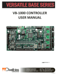
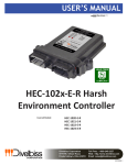
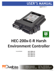
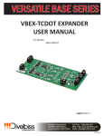
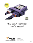
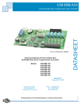
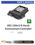
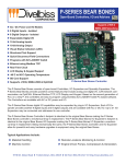
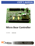
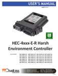
VERSATILE BASE SERIES
VB-1000 CONTROLLER
USER MANUAL
Revision: 1
Divelbiss Corporation
9778 Mt. Gilead Road,
Fredericktown, Ohio 43019
Toll Free: 1-800-245-2327
Web: http://www.divelbiss.com
Email: [email protected]
2012001.1
Table of Contents
Manual Contents
Getting Started
How to Use this Manual........................................................................ 3
Configuring the VB-1000 Target in EZ LADDER Toolkit........................... 4
Loading the VB-1000 Controller’s Kernel............................................... 4
Getting to Know the VB-1000 Layout and Connections......................... 6
VB-1000 Configuration Jumper Summary............................................. 8
VB-1000 Features
Programming Port............................................................................... 10
Watchdog LED..................................................................................... 11
Programmable LED.............................................................................. 11
Input Power......................................................................................... 11
Mounting............................................................................................. 12
Digital Inputs....................................................................................... 13
High Speed Counter / General Purpose Inputs.................................... 13
Digital Outputs..................................................................................... 16
Pulse Width Modulation Outputs........................................................ 17
Analog Inputs....................................................................................... 19
General Purpose RS232 Serial Port...................................................... 21
CAN Networking Ports......................................................................... 21
VB-1000 Target Setting Options........................................................... 22
Expansion Options............................................................................... 22
EEPROM Memory................................................................................ 23
VB-1000 Specifications........................................................................ 24
WARNING!!
The VB-1000, as with other programmable controllers must not be used alone in applications
which could be hazardous to personnel in the event of failure of this device. Precautions
must be taken by the user to provide mechanical and/or electrical safeguards external to this
device. This device is NOT APPROVED for domestic or human medical use.
VB-1000 User Manual
Document #: 2012001.1.pdf
Divelbiss Corporation • 9778 Mt. Gilead Road • Fredericktown, Ohio 43019 • 1-800-245-2327 • www.divelbiss.com
PAGE 1 of 24
Getting Started
This section explains how to read this manual and understand the symbols and information that it contains.
To begin using your VB-1000 Controller, you will need to follow these steps:
• Install EZ LADDER Toolkit if not already installed (not included).
• Configure the VB-1000 Controller in the EZ LADDER Toolkit Project Settings.
• Connect the Input Power.
• Using purchased or self-made cable, connect the Programming Port.
• Write a ladder diagram program or use a sample program provided on the EZ LADDER CD.
• Install the VB-1000 Kernel if this is a new unit from the factory.
• Download and run the program on the VB-1000 Controller.
Refer to the appropriate sections of this manual for details on the above items.
Getting Started
How to Use this Manual
In this manual, the following conventions are used to distinguish elements of text:
BOLD
italic
SMALL CAPS
Denotes labeling, commands, and literal portions of syntax that must appear exactly as shown.
Used for variables and placeholders that represent the type of text to be entered by the user.
Used to show key sequences or actual buttons, such as OK, where the user clicks the OK button.
In addition, the following symbols appear periodically in the left margin to call the readers attention to specific details in the text:
Warns the reader of a potential danger or hazard associated with certain actions.
Appears when the text contains a tip that is especially useful.
Indicates the text contains information to which the reader should pay particularly close
attention.
All Specifications and Information Subject to Change without Notice
VB-1000 User Manual
Document #: 2012001.1.pdf
Divelbiss Corporation • 9778 Mt. Gilead Road • Fredericktown, Ohio 43019 • 1-800-245-2327 • www.divelbiss.com
PAGE 3 of 24
Getting Started
Configuring the VB-1000 Target in EZ LADDER Toolkit
Before you can program and use the VB-1000 Controller, it must be configured as a target within the EZ LADDER Toolkit. For help
with installing or using EZ LADDER, please refer to the EZ LADDER User Manual.
1. In EZ LADDER, from the File Menu at the top, click PROJECT then SETTINGS. This will open the Project Settings Window.
Select VB-1000 as the target from the choices. Refer to Figure 1.1. Verify the Port is correct and the baud rate is 57600.
Figure 1.1 - Project Settings Window
2. Click OK. This will close the Project Settings Window, saving the VB-1000 as the target for this ladder diagram project.
Loading the VB-1000 Controller’s Kernel
THE VB-1000 WILL NOT FUNCTION UNLESS
THIS STEP (KERNEL LOADING) IS COMPLETED.
The kernel is the firmware for the controller and to provide greater flexibility and reliability, VB-1000 controllers are factory shipped
without a kernel. If this is a new unit from the factory, it will be necessary to load the kernel before a ladder program can be downloaded. If the kernel is already loaded, this step is not required. To upgrade a kernel, see the EZ LADDER User’s Manual.
VB-1000 User Manual
Document #: 2012001.1.pdf
Divelbiss Corporation • 9778 Mt. Gilead Road • Fredericktown, Ohio 43019 • 1-800-245-2327 • www.divelbiss.com
PAGE 4 of 24
Getting Started
To install the VB-1000’s kernel:
1. Verify the target has been configured (see Configuring the VB-1000 Target in EZ LADDER Toolkit).
2. Connect the Programming cable(s) from the computer to the VB-1000. See Programming Port in the VB-1000 Features section.
3. Create a small one-rung program with a normally open (direct contact) and an output tied together. You may also open a preexisting program for the VB-1000. EZ LADDER version 1.0.4.4 and later includes a sub-directory (...EZ LADDER\Kernel Install Start
Programs\)which has starter programs for each target to load the kernel. Choose GetStarted_VB-1000.dld.
4. Click the
(Compile) button
5. Click the
(Monitor) button to change from the ‘Edit’ to ‘Monitor’ Mode.
6. Click the
(Connect) button to connect to the target. A dialog will appear automatically when no kernel is
loaded. If this dialog does not appear, click PROJECT then BOOTLOADER.
7. Click the BROWSE button and select the target’s kernel (by part number) located by default at C:\Program Files\EZ
Ladder\Kernel\
The following are kernel names and descriptions:
File Name Description
VB_1000.dat
Kernel for VB-1000
VB-1000 User Manual
To be Used on (Part number)
VB-1000 (plus VB-1000 with VBEX-XXXX Expansion
Document #: 2012001.1.pdf
Divelbiss Corporation • 9778 Mt. Gilead Road • Fredericktown, Ohio 43019 • 1-800-245-2327 • www.divelbiss.com
PAGE 5 of 24
Getting Started
8. Click the OPEN button to finish the kernel selection. Make sure the correct kernel is chosen.
9. Click the UPDATE TARGET button to install the kernel.
10. A dialog box will appear to show the status of the kernel installation. This could take a couple of minutes to install.
11. When the dialog windows close, the installation is complete. The VB-1000 is ready to use and may be connected to
and programs may be downloaded.
Getting to Know the VB-1000 Layout and Connections
The VB-1000 Controller is designed to provide powerful programmable features in versatile, open-board format. All real world connections to the VB-1000 (except the programming port) are via 5mm terminal blocks located near the printed circuit board’s edge.
Refer to Figure 1.2, it illustrates the VB-1000 Controller’s basic layout and locations for connections and configuration jumpers.
VB-1000 User Manual
Document #: 2012001.1.pdf
Divelbiss Corporation • 9778 Mt. Gilead Road • Fredericktown, Ohio 43019 • 1-800-245-2327 • www.divelbiss.com
PAGE 6 of 24
Getting Started
DIGITAL OUTPUTS
DIGITAL OUTPUTS
GROUP A
GROUP B
CAN PORT
TERMINATION
COUNTER
JUMPERS
DE-BOUNCE
CAN PORT 0
JUMPERS
CONNECTIONS
VBEX
EXPANSION PORT
CAN PORT 4
CONNECTIONS
COUNTER
CHANNEL A LED
COUNTER A
RS232 SERIAL
NPN/PNP JUMPER
PORT
HIGH SPEED
RS232 PROGRAM
COUNTER
PORT
CONNECTIONS
DIGITAL OUTPUT
COUNTER B
STATUS LEDS
NPN/PNP JUMPER
DIGITAL INPUT
COUNTER
STATUS LEDS
CHANNEL B LED
WATCHDOG
STATUS LED
DIGITAL INPUTS
PROGRAMMABLE
GROUP B (IN6-IN11)
LED
DIGITAL INPUTS
GROUP A (IN0-IN5)
INPUT POWER
CONNECTIONS
ANALOG INPUT
+V OUTPUT FOR
CONFIGURATION
POWER TO
JUMPERS x 14
INPUT DEVICES
COMMON FOR
INPUT DEVICES
ANALOG INPUT CONNECTIONS
(SIGNAL & COMMON)
Figure 1.2 - VB-1000 Features
VB-1000 User Manual
Document #: 2012001.1.pdf
Divelbiss Corporation • 9778 Mt. Gilead Road • Fredericktown, Ohio 43019 • 1-800-245-2327 • www.divelbiss.com
PAGE 7 of 24
Getting Started
VB-1000 Configuration Jumper Summary
As the VB-1000 Controller is designed to provide powerful programmable features in versatile, open-board format; on-board option
jumpers must be configured for proper operation. Below is a summary of the jumper settings found on the VB-1000 controller. Each
of these jumpers and their specific operational characteristics is detailed in later sections of this manual.
J1, J2: CAN PORT TERMINATION JUMPERS
Jumper ID
Shunt Installed Pin 1 to Pin 2
Shunt Installed Pin 2 to Pin 3
J1
CAN Port 0 with NO Termination Resistor
CAN Port 0 with 120 Ω Termination Resistor
J2
CAN Port 4 with NO Termination Resistor
CAN Port 4 with 120 Ω Termination Resistor
J3-J6: HIGH SPEED COUNTER INPUTS CONFIGURATION JUMPERS
Jumper ID
Shunt Installed Pin 1 to Pin 2
Shunt Installed Pin 2 to Pin 3
J3
Counter Channel A Configured for NPN (1.5K Ω P/U)
Counter Channel A Configured for PNP
J4
Counter Channel B Configured for NPN (1.5K Ω P/U)
Counter Channel B Configured for PNP
J5
Counter Channel A De-bounce Enabled
Counter Channel A De-bounce Disabled
J6
Counter Channel B De-bounce Enabled
Counter Channel B De-bounce Disabled
J7-J20: ANALOG INPUTS CONFIGURATION JUMPERS
Jumper ID
Shunt Installed Pin 1 to Pin 2
Shunt Installed Pin 2 to Pin 3
J7
Analog Input 1 (AN1) Configured for 0-20mADC
Analog Input 1 (AN1) Configured for Voltage
J8
Analog Input 2 (AN2) Configured for 0-20mADC
Analog Input 2 (AN2) Configured for Voltage
J9
Analog Input 2 (AN2) Configured for 0-10VDC
Analog Input 2 (AN2) Configured for 0-5VDC
J10
Analog Input 1 (AN1) Configured for 0-10VDC
Analog Input 1 (AN1) Configured for 0-5VDC
J11
Analog Input 0 (AN0) Configured for 0-10VDC
Analog Input 0 (AN0) Configured for 0-5VDC
J12
Analog Input 0 (AN0) Configured for 0-20mADC
Analog Input 0 (AN0) Configured for Voltage
J13
Analog Input 5 (AN5) Configured for 0-20mADC
Analog Input 5 (AN5) Configured for Voltage
J14
Analog Input 6 (AN6) Configured for 0-20mADC
Analog Input 6 (AN6) Configured for Voltage
J15
Analog Input 6 (AN6) Configured for 0-10VDC
Analog Input 6 (AN6) Configured for 0-5VDC
J16
Analog Input 5 (AN5) Configured for 0-10VDC
Analog Input 5 (AN5) Configured for 0-5VDC
J17
Analog Input 3 (AN3) Configured for 0-10VDC
Analog Input 3 (AN3) Configured for 0-5VDC
J18
Analog Input 4 (AN4) Configured for 0-10VDC
Analog Input 4 (AN4) Configured for 0-5VDC
J19
Analog Input 3 (AN3) Configured for 0-20mADC
Analog Input 3 (AN3) Configured for Voltage
J20
Analog Input 4 (AN4) Configured for 0-20mADC
Analog Input 4 (AN4) Configured for Voltage
Jumper Example: Pull
Jumper as shown and
install from Pins 1 to 2
or Pins 2 to 3 based on
setting required.
VB-1000 User Manual
Document #: 2012001.1.pdf
Divelbiss Corporation • 9778 Mt. Gilead Road • Fredericktown, Ohio 43019 • 1-800-245-2327 • www.divelbiss.com
PAGE 8 of 24
VB-1000 Features
This section explains the Versatile Base, Model 1000 (VB-1000) hardware features, options and information regarding
EZ LADDER Toolkit for basic operation.
VB-1000 Features
Programming Port
The VB-1000 is programmed using its Programming Port (PGM1). This RS232 serial port is only to be used for programming using
Divelbiss EZ LADDER Toolkit software. This is not a general purpose port and may not be used in any other capacity than programming the controller itself.
The Programming Port defaults to:
Baud: Parity: Data Bits: Stop Bits : 57600
None
8
1
An SI-PGM programming cable (purchased separately) is required to establish communications between EZ LADDER Toolkit and the
VB-1000 controller. This cable connects to a standard 9-pin RS232 Serial port on a computer and plugs into the VB-1000 PGM1 port
using a standard phono-jack connection. Figure 2-1 illustrates this connection.
It is important that cable plugged into PGM1 is seated properly (plugged in as far as it will go). Failure to insure this connection may
result in communication errors or failure to establish communication between the VB-1000 controller and EZ LADDER Toolkit.
Figure 2.1 - Programming Port Connection
VB-1000 User Manual
Document #: 2012001.1.pdf
Divelbiss Corporation • 9778 Mt. Gilead Road • Fredericktown, Ohio 43019 • 1-800-245-2327 • www.divelbiss.com
PAGE 10 of 24
VB-1000 Features
Watchdog LED
The operating status of the VB-1000 can be determined the by Watchdog LED. When the Watchdog LED is flashing at a slow rate,
approximately once per second, then there is no ladder program executing. When the Watchdog LED is flashing at a fast rate (several times per second), a program has been loaded and it is executing.
If the Watchdog appears to be flickering at a very fast rate, the Kernel is not running. Either the kernel needs to be installed or the
controller reset to restart the kernel if it is installed.
Should the Watchdog LED not flash at all, first check the input power. If the input power is correct and there is still no Watchdog
LED, contact Divelbiss Technical Services.
Programmable LED
The VB-1000 provides a user-programmable status LED. This LED is programmed in the ladder diagram by using the PLED variable
that is automatically created when the target is selected. The programmer may utilize this LED as desired.
Input Power
The VB-1000 is powered using 8-32VDC. The main power terminals (VIN , ) provide power for the controller logic only. Additional terminals are provided for supplying power for digital input and digital outputs. Refer to Figure 1.2 for identifying terminals and
terminal locations on the VB-1000. Refer to the VB-1000 Specifications section of this manual for input current requirements.
While the digital I/O have separate terminals for power, if using the same power supply for logic and digital I/O, make sure it is sized
appropriately to handle the output loads.
The input power can be monitored in the ladder diagram via an internal power monitor (analog input). This analog input is accessed in the ladder diagram by using the PMON variable that is automatically created when the VB-1000 target is selected. This
PMON variable represents the raw analog input value of the input power.
This value must be scaled before it is used in a ladder diagram program. The following is an example ladder diagram program to
read the PMON input and scale it for actual input voltage. Refer to Figure 2.2.
PMON:
R_AN2:
R_Temp:
AinScale:
MaxScale:
InputV:
Power Monitor Analog Input (Integer) - Automatically created
Variable used to store converted value of PMON as a real variable type. This is required for calculations.
Variable used to temporarily store values (real variable type) during calculations.
Variable used to store maximum analog input scale value (real variable type).The default value = 1023.0
Variable used to store the maximum input voltage scale (real variable type). The default value = 40.0
Scaled analog input representing Input Voltage (real variable type)
Figure 2.2 - Scaling the Power Monitor Analog Input
Even with the scaling in Figure 2.2, the actual reading in the ladder diagram may read approximately .7V lower than the actual
input voltage. This is due to an on-board diode between the input power and the monitor circuit. It is recommended to use the
ADD function block to add .7 to the InputV variable shown (increasing the ladder diagram reading to be closer to the actual input
power).
VB-1000 User Manual
Document #: 2012001.1.pdf
Divelbiss Corporation • 9778 Mt. Gilead Road • Fredericktown, Ohio 43019 • 1-800-245-2327 • www.divelbiss.com
PAGE 11 of 24
VB-1000 Features
Mounting
The VB-1000 is designed to be sub-plate mounted using standoffs and screws (purchased separately). #6 hardware should be used
for each of the four mounting holes provided. Refer to Figure 2.3 for mounting hole dimensions and locations.
Figure 2.3 - VB-1000 Mounting
VB-1000 User Manual
Document #: 2012001.1.pdf
Divelbiss Corporation • 9778 Mt. Gilead Road • Fredericktown, Ohio 43019 • 1-800-245-2327 • www.divelbiss.com
PAGE 12 of 24
VB-1000 Features
Digital Inputs
The VB-1000 provides two groups with 6 digital inputs in each group. Each input group (IN0-IN5 and IN6-IN11) may be wired
as either sinking or sourcing. They are identified in EZ LADDER Toolkit and this manual as IN0 through IN11. EZ LADDER Toolkit
automatically creates these variables when the VB-1000 is selected as the target. Each digital input can accept an input voltage of
8-32VDC. The presence of this voltage on an input will result in the input being read as TRUE in the ladder diagram. Each of the
digital inputs are optically isolated and have on-board de-bounce circuitry.
Digital Input Group Wiring
Each digital input group may be wired as a group as sinking our sourcing. Group A (IN0-IN5) uses the CA terminal as it’s common.
Group B (IN6-IN11) uses the CB terminal as it’s common. Refer to Figure 2.4 for typical digital input connections.
A positive voltage or ground may be connected to the CA or CB terminals as required for sinking or souring. By connecting the CA/
CB terminals to ground and switching a signal (positive voltage) through an external device into the INx inputs, the group is configured as sinking. By connecting the CA/CB terminals to a positive voltage and switching the ground through an external device into
the INx inputs, the group is configured as sourcing.
To read a digital input status in a ladder diagram, place and connect the appropriate contact for your needs. The DIRECT CONTACT
and INVERTED CONTACT functions are used to read digital inputs in the ladder diagram. When placing the contact, verify you select
the correct input address (IN0 - IN11) from the provided drop-down menu.
Figure 2.4 - Typical Digital Input Connections
High Speed Counter / General Purpose Inputs
In addition to the twelve (12) digital inputs, the VB-1000 also provides two high speed counter inputs. These two inputs may be
used in the ladder diagram program as standard digital inputs using contacts (CTA and CTB) or as high speed counter inputs using
the CNTRTMR function. Each digital input can accept an input voltage of 8-32VDC and is optically isolated. Refer to Figure 2.5 for
typical connections. Figure 2.6 represents the actual high speed counter input circuitry. The +VOUT terminal is provided to connect
the power terminal of pulse devices to the input power of the controller. The
terminal is used as common for the pulse devices.
Use as General Purpose Inputs
When using either of the two high speed counter inputs (terminals CTA and CTB) as standard digital inputs, the actual input is read
in the ladder diagram program by contacts. To read a digital input status in a ladder diagram, place and connect the appropriate
contact for your needs. The DIRECT CONTACT and INVERTED CONTACT functions are used to read digital inputs in the ladder diagram. When placing the contact, verify you select the correct input (CTA or CTB) from the provided drop-down menu.
Use as High Speed Counter Inputs
When using either of the two high speed counter inputs (terminals CTA and CTB) as high speed counter inputs, the count is read
in the ladder diagram program using the CNTRTMR function block. When placing this block, ensure the correct counter channel is
selected from the provided drop-down menu (Channel 0 = CTA, Channel 1 = CTB).
VB-1000 User Manual
Document #: 2012001.1.pdf
Divelbiss Corporation • 9778 Mt. Gilead Road • Fredericktown, Ohio 43019 • 1-800-245-2327 • www.divelbiss.com
PAGE 13 of 24
VB-1000 Features
Input De-bounce
When using the High Speed Counter inputs as general purpose inputs (CTA or CTB), jumpers (J5, J6) have been provided to enable
or disable a hardware de-bounce. Typically, when using the inputs as general purpose inputs, the de-bounce should be enabled and
when using the inputs as high speed counter inputs, the de-bounce should be disabled. With de-bounce enabled, high speed counting will be limited as the input frequency is limited. Figure 2.7 illustrates the de-bounce jumper configurations of J5 and J6.
Figure 2.5 - Typical High Speed Counter Input Connections
NPN / PNP Input Configuration
The High Speed Counter Inputs CTA and CTB may be configured to interface to NPN or PNP input devices as shown in Figure 2.5.
When configured for PNP, the input device sources the power to the counter input. When configured for NPN, the counter input is
pulled to common and an internal pull-up resistor is enabled on the counter input.
Counter Configuration Jumpers
All the features described for enabling the de-bounce or configuring for NPN / PNP operation are listed below. Refer to Figure 1.2 in
the Getting to Know the VB-1000 Layout and Connections in the Getting Started section of this manual for actual jumper locations
and pin number identification.
J3-J6: HIGH SPEED COUNTER INPUTS CONFIGURATION JUMPERS
Jumper ID
Shunt Installed Pin 1 to Pin 2
Shunt Installed Pin 2 to Pin 3
J3
Counter Channel A Configured for NPN (1.5K Ω P/U)
Counter Channel A Configured for PNP
J4
Counter Channel B Configured for NPN (1.5K Ω P/U)
Counter Channel B Configured for PNP
J5
Counter Channel A De-bounce Enabled
Counter Channel A De-bounce Disabled
J6
Counter Channel B De-bounce Enabled
Counter Channel B De-bounce Disabled
VB-1000 User Manual
Document #: 2012001.1.pdf
Divelbiss Corporation • 9778 Mt. Gilead Road • Fredericktown, Ohio 43019 • 1-800-245-2327 • www.divelbiss.com
PAGE 14 of 24
VB-1000 Features
Figure 2.6 - High Speed Counter Input Circuitry
VB-1000 User Manual
Document #: 2012001.1.pdf
Divelbiss Corporation • 9778 Mt. Gilead Road • Fredericktown, Ohio 43019 • 1-800-245-2327 • www.divelbiss.com
PAGE 15 of 24
VB-1000 Features
Digital Outputs
The VB-1000 includes 8 on-board digital outputs. They are identified in the EZ LADDER Toolkit and this manual as OT0 - OT7 and
these variables are automatically created when the VB-1000 is selected as the target. These outputs are sourcing, therefore an
energized output will source an output voltage equal to the controller input voltage. Refer to Figure 2.7 for typical output connections.
The outputs are divided into two groups of four outputs each. Group A consists of OT0 - OT3 while Group B consists of OT4 - OT7.
Each output group requires an external power connection and source to supply power for the outputs. Group A power is supplied
by the +VA terminal while Group B power is supplied by the +VB terminal. The +VA and +VB terminals and output groups allow for
output loads to be controlled at different voltages. Independent and different supply voltages (8-32VDC) may be connected to +VA
and +VB individually.
+VA and +VB may be connected to different voltages, but the power supplies connected must have the same common (ground) as
the VB-1000. Failure to use the same common for the +VA, +VB and VIN may cause unwanted operation and may cause damage to
the VB-1000.
Each output can drive a load up to maximum current rating listed in the specifications section (resistive) and includes an automatic
over-current shutdown safety. In the event an over current condition exists, the output will shut down. This shut down condition is
reset when the output is turned off (set to false) in the ladder diagram.
Each output requires a minimum load to operate correctly. Depending upon the device connected to an output, a minimum load
resistor may be required. If the output is ON or true regardless of the ladder diagram program, connect a 470Ω to 1KΩ load from
the output to input power common.
Each digital output may be configured and used as a digital output or as a Pulse Width Modulation (PWM) output. Each output
may only be used as either digital output or PWM output only. For information on using digital outputs as PWM outputs, refer to
the Pulse Width Modulation Outputs Section of this manual.
To control a digital output in a ladder diagram, place and connect the appropriate coil for your needs. The DIRECT COIL and INVERTED COIL functions are used to control digital outputs in the ladder diagram. When placing the coil, verify you select the correct
output address (OT0 - OT7) from the provided drop-down menu.
Figure 2.7 - Typical Digital Output Connections
In addition to controlling the outputs, the status of each digital output may be monitored for an OK or Fault status. When the VB1000 target is configured in EZ LADDER, 8 status variables are created automatically, identified (STAT0 - STAT7). These variables indicate the status of the output and may be used in the program as any boolean variable (DIRECT CONTACT or INVERTED CONTACT). A
High or True condition indicates that the output is functioning properly while a Low or False condition indicates a fault condition of
the output (open load or overload). This condition is only valid when the output is turned on in the ladder diagram program.
VB-1000 User Manual
Document #: 2012001.1.pdf
Divelbiss Corporation • 9778 Mt. Gilead Road • Fredericktown, Ohio 43019 • 1-800-245-2327 • www.divelbiss.com
PAGE 16 of 24
VB-1000 Features
Pulse Width Modulation Outputs
As previously noted, the VB-1000 includes 8 on-board digital outputs that may be configured individually and exclusively as either
digital outputs or pulse width modulation outputs; therefore, each output may only be used as either digital output or PWM output.
Before Pulse Width Modulation outputs may be used in the ladder diagram, the Pulse Width Modulation Properties must be configured in EZ LADDER Toolkit.
To Configure Pulse Width Modulation (PWM) Outputs in EZ LADDER Toolkit:
1. In EZ LADDER, from the File Menu at the top, click PROJECT then SETTINGS. This will open the Project Settings
Window. The VB-1000 was previously selected.
2. Click the PROPERTIES button. The VB-1000 Properties Window will open. Refer to Figure 2.8.
Figure 2.8 - VB-1000 Properties Window
3. Click the PWM PROPERTIES button. The PWM Properties Window will open. Refer to Figure 2.9.
Figure 2.9 - PWM Properties Window
VB-1000 User Manual
Document #: 2012001.1.pdf
Divelbiss Corporation • 9778 Mt. Gilead Road • Fredericktown, Ohio 43019 • 1-800-245-2327 • www.divelbiss.com
PAGE 17 of 24
VB-1000 Features
4. Click the ADD button in the PWM Properties window.
5. In the ADD PWM dialog, select the channels to install. To select multiple PWM channels, hold the CTRL key while
clicking on the channel. Refer to Figure 2.10.
The channels are as follows:
Digital Output 0 (OT0) =
Digital Output 1 (OT1) =
Digital Output 2 (OT2) =
Digital Output 3 (OT3) =
PWM 0
PWM 1
PWM 2
PWM 3
Digital Output 4 (OT4) =
Digital Output 5 (OT5) =
Digital Output 6 (OT6) =
Digital Output 7 (OT7) =
PWM 4
PWM 5
PWM 6
PWM 7
Figure 2.10 - ADD PWM Window
6. Click OK to close the ADD PWM dialog. The next step is configuring the frequencies.
7. Enter the desired frequency for Clock A and Clock B (if installed). The VB-1000 has 8 available PWM Channels. These channels are either controlled with Clock A or Clock B. This allows two different PWM frequencies.
The Minimum and Maximum frequencies are displayed in the PWM Properties dialog. The frequency for
Clock A and Clock B must be in this range. Refer to Figure 2.9.
Due to limitations of hardware, the Desired Frequency and Actual Frequency may vary. The Actual Frequency will be
the closest attainable frequency to the entered Desired Frequency.
8. Click OK to close the PWM Properties Window. Click OK to close the VB-1000 Properties Window and click OK to close
the Project Settings Window.
With the Pulse Width Modulation Outputs configured in EZ LADDER, they can now be used in the ladder diagram project. The
PWM channel(s) are controlled in the ladder diagram by the PWM and PWM_FREQ function blocks. For each PWM channel required, a PWM function block is required. Typically, PWM Outputs operate at a set frequency while the Duty Cycle is adjusted to
vary the output. The Duty Cycle is a variable input to the PWM function block. In the event the frequency must be changed during
operation, the PWM_FREQ function block is used. Refer to the EZ LADDER Toolkit User’s Manual for more detail regarding function
blocks and variables.
When configuring any output (OT0 - OT7) to be used as a PWM output, the automatically created boolean variable used for controlling the output as a digital output is automatically removed. Likewise, when an output (OT0 - OT7) configured for PWM is removed
from the PWM Properties, the digital output boolean variable is re-created automatically. An output cannot exist in the ladder
diagram as a PWM output and Digital output simultaneously.
Whether used as PWM or Digital Outputs, OT0 - OT7 have the same characteristics and typical connections. See Figure 2.7.
VB-1000 User Manual
Document #: 2012001.1.pdf
Divelbiss Corporation • 9778 Mt. Gilead Road • Fredericktown, Ohio 43019 • 1-800-245-2327 • www.divelbiss.com
PAGE 18 of 24
VB-1000 Features
Analog Inputs
The VB-1000 provides 7 on-board, 10-bit resolution analog inputs. Each analog input will accept an input of 0-5VDC, 0-10VDC or
0-20mADC. The analog input ranges and types are configured using jumpers (J7 - J20) . These jumpers should be configured for the
correct inputs prior to actually connecting the analog inputs. Analog Input 7 (AN7) is the input power monitor and cannot be used
as an external analog input. Refer to the Input Power Section in the Getting Started section of this manual for more details on AN7.
Each analog input is represented in the EZ LADDER Toolkit ladder diagram using variables labeled AN0 - AN6. These variables were
created automatically when the VB-1000 target was selected in the Project Settings Window.
Each variable (AN0- AN6) will represent the actual voltage or current reading on the input (based on the range and type) as an integer number (0-1023). To use the analog input reading, place the appropriate analog input variable as an input to function blocks.
Figure 2.12 represents the internal analog input circuits and dip switch settings.
Analog Configuration Jumpers
Each of the analog inputs (AN0 - AN6) have two individual configuration jumpers. These jumpers determine the type of analog input
and the range of operation. For each analog input, one jumper determines if the analog input is configured for current (0-20mADC)
or voltage (0-5VDC/0-10VDC). The second jumper determines the range of operation when configured for voltage (0-5VDC or
0-10VDC). Refer to Figure 1.2 in the Getting to Know the VB-1000 Layout and Connections in the Getting Started section of this
manual for actual jumper locations and pin number identification.
J7-J20: ANALOG INPUTS CONFIGURATION JUMPERS
Jumper ID
Shunt Installed Pin 1 to Pin 2
Shunt Installed Pin 2 to Pin 3
J7
Analog Input 1 (AN1) Configured for 0-20mADC
Analog Input 1 (AN1) Configured for Voltage
J8
Analog Input 2 (AN2) Configured for 0-20mADC
Analog Input 2 (AN2) Configured for Voltage
J9
Analog Input 2 (AN2) Configured for 0-10VDC
Analog Input 2 (AN2) Configured for 0-5VDC
J10
Analog Input 1 (AN1) Configured for 0-10VDC
Analog Input 1 (AN1) Configured for 0-5VDC
J11
Analog Input 0 (AN0) Configured for 0-10VDC
Analog Input 0 (AN0) Configured for 0-5VDC
J12
Analog Input 0 (AN0) Configured for 0-20mADC
Analog Input 0 (AN0) Configured for Voltage
J13
Analog Input 5 (AN5) Configured for 0-20mADC
Analog Input 5 (AN5) Configured for Voltage
J14
Analog Input 6 (AN6) Configured for 0-20mADC
Analog Input 6 (AN6) Configured for Voltage
J15
Analog Input 6 (AN6) Configured for 0-10VDC
Analog Input 6 (AN6) Configured for 0-5VDC
J16
Analog Input 5 (AN5) Configured for 0-10VDC
Analog Input 5 (AN5) Configured for 0-5VDC
J17
Analog Input 3 (AN3) Configured for 0-10VDC
Analog Input 3 (AN3) Configured for 0-5VDC
J18
Analog Input 4 (AN4) Configured for 0-10VDC
Analog Input 4 (AN4) Configured for 0-5VDC
J19
Analog Input 3 (AN3) Configured for 0-20mADC
Analog Input 3 (AN3) Configured for Voltage
J20
Analog Input 4 (AN4) Configured for 0-20mADC
Analog Input 4 (AN4) Configured for Voltage
It is recommended that analog input jumper settings be configured prior to connecting the analog input. In addition, when configuring for 0-20mADC (current), the voltage selector jumper (0-5V or 0-10V) should be set for 0-5VDC (or pin 2 to pin 3). Failure to
configure prior to connecting or improper configuration may result in incorrect readings or even damage to the VB-1000 controller.
Analog Input Connections
Each of the analog inputs are single-ended connections (they all use the same common, the same as the VIN). A single terminal is
provided for each analog input labeled ANx, where x represents the analog input number. Two
terminals are provided as an
convenient common return point. If the device connected to an analog input requires a + voltage, you must provide this externally
or using the +VOUT terminals located near the controller’s input power terminals. Figure 2.11 illustrates the typical connections for
analog inputs. Figure 2.12 illustrates the analog input circuitry. It is recommended to use twisted-pair, shielded wire when connecting devices to the analog inputs. Earth ground is typically only connected at one end of the shielded wire.
VB-1000 User Manual
Document #: 2012001.1.pdf
Divelbiss Corporation • 9778 Mt. Gilead Road • Fredericktown, Ohio 43019 • 1-800-245-2327 • www.divelbiss.com
PAGE 19 of 24
VB-1000 Features
Figure 2.11 - Analog Input Connections
Figure 2.12 - Typical Analog Input Circuit
VB-1000 User Manual
Document #: 2012001.1.pdf
Divelbiss Corporation • 9778 Mt. Gilead Road • Fredericktown, Ohio 43019 • 1-800-245-2327 • www.divelbiss.com
PAGE 20 of 24
VB-1000 Features
General Purpose RS232 Serial Port
The VB-1000 includes an RS232 serial port (COM1). This serial port is a general purpose serial port that supports serial printing.
This port may also be used to communicate to a Modbus Master Device (the VB-1000 is a Modbus Slave). At this time, the general
purpose serial port is an output device only as there is no software support to read a serial input.
COM 1 is wired using the provided terminal RX1, TX1 and . These terminals are located along with the CAN communication
port terminals. Refer to Figure 1.2 in the Getting to Know the VB-1000 Layout and Connections in the Getting Started section of
this manual for actual terminal locations. Ensure that TX and RX are swapped between the VB-1000 and the serial communication
device.
COM 1 supports Modbus and the SERIAL_PRINT function block. Before COM 1 may be used, it must be configured to Serial Print or
as Modbus Slave Port in the Project Settings.
To configure COM 1 as a Modbus Slave, click PROJECT then SETTINGS. Click the MODBUS button in the Project Settings Dialog. The
Modbus Setup dialog will open. Using the check box, enable Modbus. Configure the Modbus settings required to communicate to
the Modbus Master. Click OK to save and close the Modbus Setup and click OK to close the Project Settings.
To configure COM 1 to serial print, click PROJECT then SETTINGS. Click the PROPERTIES button in the Project Settings Dialog. The
VB-1000 Properties dialog will open. Click the SERIAL PRINT PROPERTIES button. The Serial Properties dialog will open. Configure
the serial settings required to communicate to device connected to COM 1. Click OK to save and close the Serial Properties, click OK
to close the VB-1000 Properties and click OK to close the Project Settings.
CAN Networking Ports
The VB-1000 provides two on-board CAN bus interface ports. These CAN ports may be used for additional communications and
networking including SAE J1939 and the Divelbiss proprietary OptiCAN Network.
The on-board CAN ports are CAN 0 and CAN 4 respectively. To use the VB-1000’s CAN ports as either SAE J1939 or OptiCAN, it
will be necessary to configure certain parameters. These parameters are configured from the VB-1000 Properties Window in the
Project Settings. As these settings vary greatly and are software based only, please refer to the EZ LADDER Toolkit User’s Manual for
details on configuring, using and implementing CAN port networking including all relevant function blocks for J1939 and OptiCAN.
The CAN ports should be wired according to established practices for CAN networks. Figure 2.13 illustrates typical CAN Port connections. The VB-1000 provides 3 terminals for each CAN port (H, L and earth ground). The CAN HI should be connected to the H
terminal. The CAN LOW should be connected to the L terminal. The Shield should be connected to the earth ground terminal (only
one end of the shield should be connected to earth ground). Refer to Figure 1.2 in the Getting to Know the VB-1000 Layout and
Connections in the Getting Started section of this manual for actual terminal locations.
Figure 2.13 - Typical CAN Port Connections
VB-1000 User Manual
Document #: 2012001.1.pdf
Divelbiss Corporation • 9778 Mt. Gilead Road • Fredericktown, Ohio 43019 • 1-800-245-2327 • www.divelbiss.com
PAGE 21 of 24
VB-1000 Features
As shown in Figure 2.13, when devices are at the end of the communications lines, 120 ohm terminating resistors are required for
correct functionality. The VB-1000 includes optionally enabled terminating resistors for each CAN port (0 and 4). The terminating
resistors are enabled and disabled using jumpers (J1 and J2). Figure 2.14 illustrates the on-board terminating resistor jumper option. Refer to Figure 1.2 in the Getting to Know the VB-1000 Layout and Connections in the Getting Started section of this manual
for actual jumper locations.
J1, J2: CAN PORT TERMINATION JUMPERS
Jumper ID
Shunt Installed Pin 1 to Pin 2
Shunt Installed Pin 2 to Pin 3
J1
CAN Port 0 with NO Termination Resistor
CAN Port 0 with 120 Ω Termination Resistor
J2
CAN Port 4 with NO Termination Resistor
CAN Port 4 with 120 Ω Termination Resistor
Figure 2.14 - CAN Port Terminations and Jumpers
VB-1000 Target Setting Options
To use some of the function blocks and features on the VB-1000, it may be required to configure additional target properties in the
Project Settings Dialog Box. Click PROJECT then SETTINGS. With the VB-1000 selected, click PROPERTIES.
The following are items that must be configured in the VB-1000 Project Settings, Properties Dialog.
PWM Properties
This is used to configure the Pulse Width Modulation channels (see Pulse Width Modulation Outputs).
J1939 Properties
This is where SAE J1939 Communications is enabled and configured. Refer to the J1939 section of the EZ
LADDER Manual.
OptiCAN Properties
This is where OptiCAN Communications is enabled and configured. Refer to the OptiCAN section of the
EZ LADDER Manual.
Serial Print Properties
This is used if the Serial Print function block is to be used to transmit data to an external device using the
General Purpose Serial port. The serial port is configured here.
Expansion Options
The VB-1000 is designed for field installation of expansion boards (VBEXP-xxxx). The VB-1000 can be expanded by adding one
board, vertically mounted and connected to the EXP1 port. For installation of expansion options, see the Expansion Option’s
Manual. For a list of available expansion options, contact Divelbiss Corporation.
VB-1000 User Manual
Document #: 2012001.1.pdf
Divelbiss Corporation • 9778 Mt. Gilead Road • Fredericktown, Ohio 43019 • 1-800-245-2327 • www.divelbiss.com
PAGE 22 of 24
VB-1000 Features
EEPROM Memory
As one of the standard features of PLC on a Chip™ and EZ LADDER Toolkit, the VB-1000 supports the use EEPROM memory that
may be used to store and recall boolean, integer, real and timer values in non-volatile memory in the ladder diagram. This can be
used to store field adjustable set points and more.
The VB-1000 supports 2792 bytes of EEPROM memory. This memory is accessed in the ladder diagram using the EEPROM_READ
and EEPROM_WRITE Function blocks. The same variable type that writes to the EEPROM location should be used to read the EEPROM location. A memory map is recommended for organizing variables stored in EEPROM.
Each EEPROM address is absolute and is one byte in size. Boolean variables fill two bytes while all other variable types fill four
bytes of EEPROM. When writing a boolean to address 0, the actual variable will use addresses 0 and 1 (two bytes). Should you
write an integer variable into address 0, then it would use addresses 0-3. A memory map should be created and used to assign
variable types and addresses prior to coding to ensure that variable size and types are accounted for.
Variable 1 Address - Boolean (2
bytes) uses location 0 and 1.
Variable 2 Address - Integer (4
bytes) uses location 2,3,4 and 5.
Variable 3 Address - Boolean (2
bytes) uses location 6 and 7.
EEPROM ADDRESS LOCATION
Variable & Type
0
1
2
3
4
5
6
7
8
9
Variable 1 (Boolean)
Variable 2 (Integer)
Variable 3 (Boolean)
Figure 2.15 - EEPROM Memory Locations
EEPROM storage area has a limited number of write cycles; therefore it shouldn’t be used to store data which changes often and
must be re-written often. Writing often to the same location can cause the location to fail.
VB-1000 User Manual
Document #: 2012001.1.pdf
Divelbiss Corporation • 9778 Mt. Gilead Road • Fredericktown, Ohio 43019 • 1-800-245-2327 • www.divelbiss.com
PAGE 23 of 24
VB-1000 Features
VB-1000 Specifications
Processor:
Memory:
Serial Ports:
Networking:
Digital I/O:
Counters:
Analog Inputs:
PWM Outputs:
Input Power Voltage:
Input Power Current:
Operating Temp:
Program Language:
Dimensions:
Mounting:
Type:
Storage Temperature:
PLC on a ChipTM
256K Flash, 12K RAM, 2792 bytes EEPROM
1 Programming Port (Max baud: 57.6K);
1 Multipurpose Port, RS232 (Serial Print and Modbus Slave)
2 CAN Ports for Divelbiss OptiCAN and SAE J1939 Communications
Field selectable internal CAN terminating Resistors
12 Inputs & 8 Outputs on-board, Expandable using OptiCAN Network
Inputs rated 8-32VDC, 2 Groups of 6, Groups may be wired for Sinking or Sourcing
Outputs rated 4A Max SEE NOTE 1, Over-current protected. Sourcing as 2 Groups of 4 Outputs
2 Channels, Count Up, 1 - 100KHz (CTA, CTB).
Field selectable as NPN or PNP type.
2 Channels may be used as Digital Inputs in addition to Counter Inputs
7 Channels, 10-bit Resolution, field selectable as 0-20mADC, 0-5VDC or 0-10VDC
8 Channels 1.5Hz to 1KHz, Over current Protected, . 4ADC Maximum SEE NOTE 1, Sourcing 2 Groups of 4 Outputs with Individual +V Power Source Terminal for Source
8-32VDC, with internal input power monitor using AN7 (PMON)
12VDC Input: 45mA Typical (No I/O Included) standard operation
Add 5mA for Each I/O Point (Input or Output)
Output Loads additional
Power for External Sensors and Devices additional
Communications additional
-40-80°C
Ladder Logic using Divelbiss EZ LADDER Toolkit.
4.27” Wide x 8.3” Length x 1.0” Tall.
Sub Plate Mount using # 6 Hardware
Open Board
-40-85°C
NOTE 1: 4ADC Total @ up to 50 ° C Maximum per 2 Output Channels. Channels paired as OT0 / OT1, OT2 / OT3, OT4 / OT5 and OT6 / OT7. Total
Current is sum of both paired output channels. See Figure 2.16 for maximum output current per output channel pair based on ambient
temperature.
Max Current Per Output Pair vs.
Temperature
Current (Amps)
5.00
4.00
3.00
2.00
Max Current
1.00
0.00
-40
-20
0
20
40
60
80
Ambient Temperature ( °C)
Figure 2.16 - Max Current for Outputs
VB-1000 User Manual
Document #: 2012001.1.pdf
Divelbiss Corporation • 9778 Mt. Gilead Road • Fredericktown, Ohio 43019 • 1-800-245-2327 • www.divelbiss.com
PAGE 24 of 24