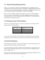
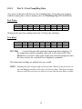
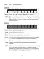
1
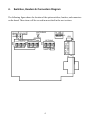
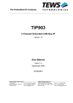
ISA PC Watchdog Board User’s Manual Berkshire Products, Inc. Phone: 770-271-0088 http://www.berkprod.com/ Rev: 3.05 © Copyright 1996, 1997,1998, 1999, 2000 PC Watchdog is a registered trademark of Berkshire Products Table of Contents 1. INTRODUCTION.............................................................................................1 2. OPERATION....................................................................................................2 3. HOW TO USE THIS MANUAL......................................................................3 4. SWITCHES, HEADERS & CONNECTORS DIAGRAM.............................4 5. SW1 & SW2 I/O MONITOR ADDRESS SWITCHES..................................5 5.1 PICKING A STANDARD ISA I/O ADDRESS (NOT RECOMENDED)...........................................5 5.2 CONFIGURING THE I/O ADDRESS ON THE SWITCHES .........................................................5 5.3 HOW DO I KNOW THE ADDRESS IS CORRECT?.................................................................6 5.4 SAMPLE I/O ADDRESSES AND SWITCH SETTINGS...............................................................6 6. SW3 - OPTION SWITCHES...........................................................................7 6.1 SWITCH #1 - RELAY #1 TEMPERATURE MODE (RTM)....................................................7 6.2 SWITCH #2 - RELAY #1 MODE (R1M)...........................................................................7 6.3 SWITCH #3 - RELAY #2 MODE (R2M)...........................................................................8 6.4 SWITCH #4 - TEMPERATURE RESET ENABLE (TRE).........................................................8 6.5 SWITCH #5 - POWER ON DELAY (POD).........................................................................8 6.6 SWITCH #6-8 - WATCHDOG DELAY TIME........................................................................9 7. CONNECTORS...............................................................................................10 7.1 J1 & J2 - RESET HEADERS..........................................................................................10 7.2 J4 - SCREW TERMINAL BLOCK......................................................................................10 7.3 J5 - DB-9 CONNECTOR................................................................................................11 7.3.1 RELAY CONTACTS...............................................................................................................................11 7.3.2 TEMPERATURE TRIP OUTPUT...............................................................................................................11 7.4 J3 - INTERNAL HEADER................................................................................................12 7.5 J6 - NMI HEADER ....................................................................................................12 8. LEDS AND BUZZER .....................................................................................13 8.1 CR2 - LEDS...............................................................................................................13 8.2 CR1 - WATCHDOG TRIP..............................................................................................13 i 8.3 BUZZER........................................................................................................................13 9. INSTALLATION............................................................................................14 10. ADVANCED PROGRAMMING INTERFACE.........................................15 10.1 DEFINING THE USER I/O PORT ADDRESS.....................................................................15 10.2 I/O PORT DEFINITIONS...............................................................................................15 10.2.1 PORT 0 - CLEAR/TEMP/DIAG DATA....................................................................................................16 10.2.2 PORT 1 - CONTROL STATUS #1..........................................................................................................17 10.2.3 PORT 2 - CONTROL STATUS #2..........................................................................................................19 10.2.4 PORT 3 - SWITCH STATUS / WATCHDOG DISABLE.................................................................................21 10.3 COMMAND MODE - COMMANDS..................................................................................22 10.3.1 IDLE COMMAND - 0X0.......................................................................................................................22 10.3.2 VERSION NUMBER (INTEGER) - 0X1....................................................................................................22 10.3.3 VERSION NUMBER (TENTH) - 0X2......................................................................................................22 10.3.4 VERSION NUMBER (HUNDREDTH) - 0X3..............................................................................................22 10.3.5 INVALID COMMAND - 0X4..................................................................................................................23 10.3.6 SWITCH SETTINGS (SW3) - 0X5........................................................................................................23 10.3.7 RESET PC - 0X6..............................................................................................................................23 10.3.8 ARM COMMANDS - 0X7 TO 0X9.........................................................................................................23 10.3.9 DELAY TIME COMMANDS - 0XA TO 0XC............................................................................................24 10.3.10 RESET RELAYS - 0XD.....................................................................................................................24 10.3.11 INVALID COMMAND - 0XE...............................................................................................................24 10.3.12 SPECIAL DIAGNOSTICS - 0XF (DO NOT USE).....................................................................................24 11. WATCHDOG PROGRAMS AND API.......................................................25 11.1 WIN 95-98-2000-NT DIRECTORY..............................................................................25 11.1.1 WIN 95-98-2000-NT\SYS_DVRS.....................................................................................................25 11.1.2 WIN 95-98-2000-NT\C_FILES........................................................................................................26 11.1.3 WIN 95-98-2000-NT\VB_FILES.....................................................................................................27 11.2 NT-DLL-STYLE DIRECTORY.....................................................................................28 11.3 OLD-FILES DIRECTORY.............................................................................................28 12. GETTING PAST THE LOGIN ON WIN95/98 AND ME.........................29 13. QUESTIONS & ANSWERS.........................................................................30 14. APPENDIX A - SPECIFICATIONS...........................................................31 15. APPENDIX B - WARRANTY......................................................................32 16. APPENDIX C - SERVICE AND TECH SUPPORT..................................33 ii 16.1 CALLING TECH SUPPORT .............................................................................................33 16.2 PRODUCT RETURNS.....................................................................................................33 17. APPENDIX D - AGENCY APPROVALS...................................................34 17.1 FCC - CLASS A........................................................................................................34 17.2 CE ...........................................................................................................................34 iii 1. Introduction The PC Watchdog board is a short 8 bit ISA card that is used to monitor a PC in order to ensure maximum system availability. The board has the following features: • • • • • • • • • • • • • • User I/O ports that can be used for enhanced watchdog control and monitoring. User I/O ports can be mapped to 3 addresses areas in I/O space. Decodes all 16 I/O address lines. Two on-board relays (DPDT - 2 form C) can be programmed to generate a 3 second pulse or latch on continuously after a watchdog initiated reset. Relay contacts available on screw terminals, a DB-9 connector, and an internal header on the board. Over temperature option monitors the internal temperature of the PC. Two temperature trip points - user programmable. With temp option a relay can be programmed for a 3 second pulse or latch on after the over temp trip occurs. Audible alarm and external signal output for the two temperature trip points. Options to allow Watchdog to hold the PC in reset after the upper trip occurs. Two externally visible LEDs show status of watchdog board. One LED lights after first watchdog generated reset as a visible indication that a watchdog reset occurred. User I/O port enables the user to control one of the relays from a user program. In special applications it can be used right from the box without any support programs when monitoring ISA address (see Section 5.1). Programmable power-on delay to allow the PC to complete its initialization sequence. 1 2. Operation This board is designed to monitor PCs used in critical applications such as: File Servers, Voice Mail Systems, BBS systems, industrial applications, etc. The idea is to make sure the PC is always available and running, especially systems that are not continuously monitored. When the PC is powered up, the PC Watchdog will wait a preset amount of time (2.5 minutes or until the first clear signal is received) to allow the PC to complete its reset and initialization sequence. After this has occurred, the PC Watchdog will start a watchdog timer running (user defined time-out period) and then wait for a user program to access an I/O port or it can monitor a user selected I/O port location such as COM (serial) port for activity. If no activity is detected by the time the watchdog timer expires, the PC Watchdog will start its reset sequence on the PC. When the PC Watchdog resets the PC it will turn on the bottom LED at the back of the board and leave it on. This provides an indication that at least one PC Watchdog reset has occurred, possibly more. There is also an I/O port that can be polled for a status bit that gets set after the PC Watchdog resets the PC. This allows an application program to determine the type of PC reset. A user program writing to a control port can clear the status bit and the LED. The PC Watchdog will also activate the two relays to indicate the reset. The options allow pulsing the relays for 3 seconds after each reset or latching them on after the first reset. To clear the latched relays, the PC will have to be powered off or reset by a pushbutton reset. The contacts are DRY closure type. If your PC Watchdog was ordered with the temperature option, the board will monitor the internal temperature of the PC. There are two standard temperature trip points available: 46°C (115°) and 56°C (133°F). At the first trip point the PC Watchdog board will activate one of the relays if the option is selected. It will also activate an audible alarm and an external signal that can be monitored at the DB-9 connector. At the second trip point the PC Watchdog can optionally pull a hard reset on the PC to stop further processing. There is also an option to allow shifting the trip points higher via software control. The trip points can be increased in 1°C increments up to 61°C (142°F) and 71°C (160°F). 2 3. How to Use This Manual The PC Watchdog board can be used in two different ways: 1: The board can be used right from the box without any user programming involved. In this case you should refer to the sections on “Switches, Headers & Connections”, “SW3 - Option Switches”, and “SW1 & SW2 I/O Monitor Address Switches”. This mode is becoming less useful as the number of ISA devices in a PC is decreasing. 2: If you write your own programs in C, C++, PASCAL, ASSEMBLER, or BASIC you will have a lot more control of the card available to you. Use sections on “Switches, Headers & Connections”, “SW3 - Option Switches”, and “Advanced Programming Interface”. This is now the best way to use the board. All users will probably want to read the section on “Questions & Answers” since it covers some common user inquiries concerning usage and monitoring strategies. Before installing the card read the section on “Connectors” for the reset cable and the “Installation” section. 3 4. Switches, Headers & Connectors Diagram 7 8 1 2 3 4 EN 5 6 7 8 OPTIONS 1 2 3 4 5 6 RTM R1M R2M TRE POD 6 USER ADD SW3 5 7 6 5 4 3 4 SW2 3 15 14 13 12 11 10 9 8 SW1 2 RELAY1 7 8 TIME J3 CR2 RELAY1 RELAY2 C NCNO C NCNO WATCHDOG TRIP PB-SW CPU RST RST 1 GND 2 J1 J2 ADDRESS MATCH 1 +5 C NC NO G The following figure shows the location of the option switches, headers, and connectors on the board. These items will be covered in more detail in the next sections. J5 J4 4 5. SW1 & SW2 I/O Monitor Address Switches Since most peripherals in a PC are now PCI, we recommend that you skip this section of the manual. Passive monitoring of ISA I/O ports is not possible unless you are using an older motherboard. To use this board you should now write your own application program to "tickle" the PC Watchdog. See Section 10 for setting the User I/O address on the board. 5.1 Picking a Standard ISA I/O Address (not recomended) All the switches on SW1 and the first 5 switches on SW2 are used to select an I/O address to monitor. Switch #6 on SW2 is used to enable the stand-alone monitoring of a system I/O address and should be on. Those users writing their own programs that access the special ports on the board directly should leave this switch off. The PCI controller on the motherboard prevents PCI I/O cycles from beeing "seen" by the ISA bus and visa-versa. The board can only monitor ISA I/O ports. In this mode of operation of the PC Watchdog you will need to analyze the operation of your PC looking for the following type of characteristics of its normal operation: • Does it access the MODEM? Set the watchdog to monitor the COM port for that MODEM. • Does it have a security device (dongle) connected to the LPT port. These devices are typically checked frequently by software. 5.2 Configuring the I/O Address on the Switches After determining the I/O device to monitor you will need to determine its I/O address. In the following section we give the addresses of some common ISA devices. You may have to consult your manuals or configuration files for the I/O addresses of the device you wish to monitor. Most manuals will describe the I/O address in terms of a Hex number such as 0x3F8 (COM1 address). However the address is really 16 bits wide so the real I/O address is 0x03F8. The early PCs only used the first 10 address lines for decoding which is the reason for the truncated address. Newer devices now decode all 16 address lines. 5 You will notice that the watchdog board is only set to decode address lines 3-15 on the ADDRESS MATCH switches, which are the upper 13 address lines. The lower three address lines; 0-2 are ignored. This means the watchdog card decodes 8 bytes of I/O space at a time. If this sounds complicated - it is! Seek the assistance of a programmer or call us if necessary. 5.3 How Do I Know the Address is Correct? When you look up the I/O address of your I/O device you may find that it has 16 or 32 bytes of I/O space allocated. An example is a network card that is in the range 0x0300 0x031F or 32 bytes. In this case you will have to experiment with the card by trying each of the four sections: 0x0300-0x0307, 0x0308-0x030F, etc. On the diskette there is a program called DIP-FIND.EXE. This program will prompt you for an I/O address, and then it will show you the required switch settings. There is an LED at the top of the board labeled Watchdog Trip. Every time the watchdog board detects an access of the I/O address that you selected it will pulse this LED. If the LED in on continuously then you have a lot of I/O activity. If the LED is off, first be sure that the EN switch (SW2 - #6) is on or up. If the LED still shows no sign of activity then you can change the ADDRESS MATCH switches while the system is running until you detect activity. 5.4 Sample I/O Addresses and Switch Settings Here are some common I/O addresses and their PC Watchdog settings: DEVICE LPT1 LPT2 COM1 COM2 COM3 COM4 ADDRESS 0x0378 0x0278 0x03F8 0x02F8 0x03E8 0x02E8 - 0x037F 0x027F 0x03FF 0x02FF 0x03EF 0x02EF SWITCHES1 1 1 1 1 1 5 4 3 2 1 0 0 0 0 0 0 0 0 0 0 0 0 0 0 0 0 0 0 0 0 0 0 0 0 0 0 0 0 0 0 1 0 0 0 0 0 0 0 9 1 1 1 1 1 1 8 1 0 1 0 1 0 7 0 0 1 1 1 1 6 1 1 1 1 1 1 5 1 1 1 1 1 1 4 1 1 1 1 0 0 3 1 1 1 1 1 1 Note 1 - a one (1) here means a switch ON or UP. A zero (0) means a switch DOWN or OPEN. 6 6. SW3 - Option Switches There is an eight-position dipswitch at the top of the board to program the operation of the watchdog board for all types of operation. The switch options are: Switch 1 2 3 4 5 6-8 Description Relay #1 Temperature Mode Relay #1 Mode Relay #2 Mode Temperature Reset Enable Power On Delay Watchdog Delay Time The switches are considered ON when the switch is UP or ON. The switch is considered OFF when the switch is DOWN or OPEN. 6.1 Switch #1 - Relay #1 Temperature Mode (RTM) ON - activate RELAY #1 when the temperature exceeds the lower trip point (default is 115°F). The mode of operation of RELAY #1 is determined by switch #2. If the temperature drops back below the trip point and then goes above it again, Relay #1 will generate another pulse if it is programmed in 3 second pulse mode. OFF - ignore temperature. 6.2 Switch #2 - Relay #1 Mode (R1M) ON - RELAY #1 will latch on after a watchdog trip (or a temperature trip if switch #1 is on). The PC will have to be powered down or the PC push-button reset will be needed to clear the relay state. A user program can also turn off the relay. OFF - RELAY #1 will pulse for 3 seconds after a watchdog trip (or a temperature trip if switch #1 is on). 7 6.3 Switch #3 - Relay #2 Mode (R2M) ON - RELAY #2 will latch on after a watchdog trip. The PC will have to be powered down or the PC push-button reset will be needed to clear the relay state. A user program can also turn off the relay. OFF - RELAY #2 will pulse for 3 seconds after a watchdog trip. A user program can take exclusive control of this relay if required. 6.4 Switch #4 - Temperature Reset Enable (TRE) ON - this will allow the PC Watchdog to reset the PC and HOLD it in reset whenever the upper temperature trip point occurs point (default is 56°C). When the PC is held in reset the CPU and other functions will stop and some disk drives will even spin down and stop. This will slow or stop the continued temperature rise. If the temperature drops to 4°C above the lower trip point then the watchdog will release the reset on the PC. OFF - do not reset the PC at the second trip point. The buzzer sound will change sound to indicate the second trip. 6.5 Switch #5 - Power On Delay (POD) ON - In this mode the watchdog board will first wait 2.5 minutes (150 seconds) after resetting the PC, or after power on. However, after this delay time it will then wait until it sees the first clear pulse from I/O port activity. Then it will arm itself. OFF - watchdog board will wait 2.5 minutes (150 seconds) after resetting the PC, or after power on, before it starts its internal watchdog timer. 8 6.6 Switch #6-8 - Watchdog Delay Time These switches set the delay time until the watchdog resets the PC. As long as the watchdog is receiving clear pulses it will continue to reset the delay time. The settings and times are shown below: Switches 6-8 OFF-OFF-OFF OFF-OFF-ON OFF-ON-OFF OFF-ON-ON Delay Time 20 Seconds 40 Seconds 1 Minute 5 Minutes Switches 6-8 ON-OFF-OFF ON-OFF-ON ON-ON-OFF ON-ON-ON Delay Time 10 Minutes 30 Minutes 1 Hour 2 Hour These times can be overridden with shorter delays by a user program. 9 7. Connectors This section covers the internal and external connections to the board. 7.1 J1 & J2 - Reset Headers There are two headers on the upper left corner board label J1 and J2. The reset cable from the front panel reset switch should be removed from the motherboard and connected to J1, which is also labeled PB-SW for push-button switch. The orientation of this cable on the header should not be critical. The enclosed cable that came with the board should be connected from J2 (labeled CPU RST) to the reset header on the motherboard. These cable connections must be done correctly for proper operation of the watchdog. From now on when you press the front panel reset button on the PC it will reset the watchdog board as well as the PC. 7.2 J4 - Screw Terminal Block This connector is a two piece connector that can be removed to simplify the attachment of wires. The block is labeled on the board for Relay #1 and Relay #2. The three switch contacts are labeled for each relay as follows: C - Common relay contact. NC - Normally closed contact. NO - Normally open contact. Do not switch more than 48 Volts or 0.5 Amps with these contacts! 10 7.3 J5 - DB-9 Connector The DB-9 connector gives access to a set of Relay #2 contacts and other signals as shown below: Pin # 1 2 3 4 5 6 7 8 9 Description External Power Module Control Relay #2 NC - Normally closed contact Relay #2 NO - Normally open contact Relay #2 COM - Common switch contact Do not connect +5V1 Lower Temperature trip2 No Connection Ground Note: Use a shielded cable to connect to this port. Connect the cable shield to pin 9. This will help attenuate any RFI from this port. Only pins 2, 3, 4, 7, and 9 should be used. 1. +5V (Pin 6) is no longer connected on Rev C-3 boards. 2. See section 7.5. 7.3.1 Relay Contacts These relay contacts must be limited to +48 Volts and 0.5 Amps. 7.3.2 Temperature Trip Output The trip line is an open collector output that will be in the off or high impedance state when the temperature is below the lower trip temperature. When the temperature exceeds the lower trip point, this pin will go low (about 0.8V) and can sink a maximum of 100mA. 11 7.4 J3 - Internal Header There is a header on the board at J3 that connects to Relay #1 and +5.0 Volts and Ground. These contacts can switch up to 48.0 Volts and 0.5 Amps for internal use in the PC. One application could be a connection to the digital switch inputs on a game port header. 7.5 J6 - NMI Header Header J6 is three pin header located at the lower right hand corner of the board. A shorting jumper can be installed on pins 1&2 or pins 2&3. When 2&3 are connected together the board works like all prior versions and provides a temperature trip signal on the DB-9 connector. When pins 1&2 are connected, the board will automatically sense this connection and provide a NMI signal (I/O Channel Check). The NMI signal will be generated about 500mS before the board resets the PC to provide time for the PC to perform clean up operations. You may need to contact your motherboard vendor about I/O ports that may need to be setup in order to enable the NMI signal to the processor. 12 8. LEDs and Buzzer 8.1 CR2 - LEDs There are two LEDs on the back of the board. After the PC powers up the PC Watchdog will wait a programmed amount of time (set by the switch option) before it enters its watchdog mode. During this time the top LED will pulse at a 1 second rate (1 second on, 1 second off). When the PC Watchdog is ready and armed it will start flashing the top LED at a ½ second rate as an indication that it is running OK. When the watchdog is within 10 seconds of resetting the PC it will flash this LED at a 1/10 second rate. If the temperature option is installed, it will also sound a short beep on the buzzer. If the watchdog board resets the PC, the top LED will return to its one second toggle rate while the it again waits for the PC to undergo a new reset sequence. When this occurs, the bottom LED will be forced on. The LED can be cleared by cycling power on the PC, pressing the front panel reset button, using the report program PC-RESET.EXE, or by a user program. 8.2 CR1 - Watchdog Trip As described earlier, this LED will emit a short pulse whenever the watchdog board receives a clear pulse as the result of I/O activity. If the I/O activity is too frequent, the LED will appear to be on continuously. When the board powers up (or after a PC reset) the trip LED will flash for about a ¼ second if there is no temp option installed. The LED will flash for about 1 second if a temperature monitor IC is found and it is working correctly. 8.3 Buzzer If you ordered the PC Watchdog with the temperature option there will be a buzzer installed on the board. When the first temperature trip occurs the buzzer will beep. When the second trip point occurs the buzzer will be on continuously. The buzzer will sound briefly when the board resets the PC. 13 9. Installation Perform these steps to install the board in your computer: A. Power down the computer and remove the cover. B. Minimize static buildup by touching the frame of the PC or the power supply case to ensure all static electricity is discharged to ground. C. Find an empty 8 or 16 bit slot and remove the back cover plate from the PC. Save the screw from the cover plate. D. Make sure the board has been properly configured (switches and jumpers). E. Remove the screw terminal block from the watchdog board if it is still attached. It will protrude too far to permit installation. F. Pay close attention to the alignment of the board and the I/O slot of the PC as you insert the board into the slot. G. Install the screw in the bracket on the back panel. H. Plug in the screw terminal block to the card through the back panel. I. Remove the front panel reset cable from the motherboard and install it at J1 on the watchdog board. J. Install the enclosed cable from J2 on the watchdog board to the reset header on the motherboard. K. Replace the cover on the PC and apply power. L. The top LED on the watchdog board should start to flash after power has been applied. 14 10. Advanced Programming Interface There is a set of registers available on the board that allows a programmer to gain additional control of the operation of the PC Watchdog. Typically the EN switch (SW2 - #6) will be in the off position disabling the monitoring of standard I/O ports since one of these registers provides a mechanism for “tickling” the watchdog. There is now an API library supplied on the diskette for Visual C and Visual Basic. There are functions in this library to provide the capability to set and test all modes described in this section. This API supports Win 95/98/2000/NT. See the diskette for documentation and sample programs. 10.1 Defining the User I/O Port Address In order to use the internal registers, you must set up their base I/O address on SW2 using switches #7 & #8 as follows: SW2 #7 OFF OFF ON ON SWITCHES #8 - OFF - ON - OFF - ON I/O ADDRESS RANGE DISABLE 0x0270 - 0x0273 0x0350 - 0x0353 0x0370 - 0x0373 As you can see from the table, if both switches are off then the user port is disabled completely. Also note that there are four (4) I/O registers (BYTE wide) on the board. 10.2 I/O Port Definitions In the following sections the 4 I/O ports will be defined. They will be listed in order of offset from the base I/O address selected with SW2. In each description there will be a table that lists the Bit Name for each position, and the Reset status of the bit if defined. If the reset state of the bit is undefined it will be shown with the letter “U”. Each port table will also list the active bit positions for reading and writing data. If a bit position is not used it will be shown with the letter “X”. 15 10.2.1 Port 0 - Clear/Temp/Diag Data Any access of this port will also reset the watchdog timer. Every time your program reads the temperature or does a dummy write, the Watchdog Trip LED should flash. Port Write: BIT WRITE RESET D7 X U D6 X U D5 X U D4 X U D3 X U D2 X U D1 X U D0 X U Writing to this port does nothing other than "tickling" the watchdog. Port Read: BIT READ RESET D7 TD7 U D6 TD6 U D5 TD5 U D4 TD4 U D3 TD3 U D2 TD2 U D1 TD1 U D0 TD0 U TD7-TD0: A read of this port will return the temperature data in degrees C if the temperature option is installed, otherwise it will return 0xF0. If the DIAG bit is set in Port 2 then reads of this port will return diagnostic data. See later sections for a detailed list of diagnostic commands. The temperature readings are updated once per second. NOTE: Reading this port returns eight (8) bits of data. However the processor on the watchdog board only writes four (4) bits at a time. Therefore you may have to read this port twice in order to be sure that the new data is stable! 16 10.2.2 Port 1 - Control Status #1 Port Write: BIT WRITE RESET D7 RLY2 0 D6 R2DS 0 D5 X U D4 X U D3 X U D2 X U D1 X U D0 X U RLY2: Writing a one to this bit will activate Relay #2 on the board. R2DS: Writing a one to this bit disables the on-board processor from controlling Relay #2 during a temperature trip or a reset. This allows you to have total control of the relay. If this bit is off, then you or the on-board processor can activate the relay. Port Read: BIT Read RESET D7 RLY2 0 D6 R2DS 0 D5 X U D4 RL1A 0 D3 RL2A 0 D2 TTRP U D1 HRBT U D0 WTRP U RLY2: Returns the status of your last write. R2DS: Returns the status of your last write. RL1A: If this bit is one it means Relay #1 is active or on. RL2A: If this bit is one it means the on-board processor has tried to turn on Relay #2. If you have set the R2DS bit then you will have overridden the processor. TTRP: If this bit is one it means the lower temperature trip point has been exceeded. HRBT: This status bit is the watchdog heartbeat. It will mirror the action of the top LED on CR2. After reset it will toggle at a 1 second rate while the watchdog is in its power-on delay. It will toggle at a ½ second rate when the watchdog arms, and it will toggle at a 1/10 second rate when the watchdog is within 10 seconds of resetting the PC. 17 WTRP: If this bit is set it means the watchdog has performed one (or more) resets on the PC as a result of a time-out or over-temp condition (if enabled). This bit is cleared whenever this port is written. Typically at power up you would test this bit and write to a log file indicating date and time of the reset. If your power up test program detects the WTRP bit is active, and you have enabled the watchdog to reset the PC in case of over temp as well; then also check the TTRP bit to see if it is also set. This will let you know that the reset was generated as a result of temperature, not a time-out. 18 10.2.3 Port 2 - Control Status #2 Port Write: BIT WRITE RESET D7 WCMD 0 D6 SSEL 0 D5 ENTP 1 D4 X U D3 TVD3 0 D2 TVD2 0 D1 TVD1 0 D0 TVD0 0 WCMD: Writing a one to this bit will put the watchdog into command mode. Be sure you have set the four (4) TVDx bits to zero first, to put the board in an idle mode. While commands are active the watchdog will continue to run its time-out counter, however Port 0 will return command response data instead of temperature data. SSEL: This bit is used in conjunction with the next port (Port 3) that allows you to read the settings on SW1 & SW2. When SSEL is one you read SW1 that is the upper 8 bits of the match address. When SSEL is zero you read the settings of SW2. This allows you to determine if a user has tampered with the switch settings. ENTP: This bit is always set to one (1) after a reset of the watchdog board to ensure compatibly with earlier versions of the board. If this bit is one AND the TRE switch on SW3 is on, then the watchdog board is enabled to hold the PC in reset if the upper temperature trip point is exceeded. TVD3-TVD0: These four (4) bits are used to change the upper and lower trip points for the temperature sensing. The value written to this port is added to the base trip points of 46°C and 56°C. This means if you write 0xF (decimal 15) to this register then you can shift the trip points up to 61° and 71° Centigrade. In command mode these bits are used to send a command to the board. See later section. Port Read: BIT READ RESET D7 WCMD 0 D6 SSEL 0 D5 ENTP 1 D4 WDIS 0 WCMD: This reflects the last value written. 19 D3 TVD3 0 D2 TVD2 0 D1 TVD1 0 D0 TVD0 0 SSEL: This reflects the last value written. ENTP: This reflects the last value written. WDIS: If this bit is set, it indicates that you have successfully disabled the watchdog board by using Port 3. When the watchdog is disabled it will not reset the PC, it will reset its internal timer and freeze it, it will not perform a reset if the upper temperature trip point is exceeded, however it will continue to update the temperature register. TVD3-TVD0: These four (4) bits return the last data written. 20 10.2.4 Port 3 - Switch Status / Watchdog Disable Port Write: BIT WRITE RESET D7 WD7 U D6 WD6 U D5 WD5 U D4 WD4 U D3 WD3 U D2 WD2 U D1 WD1 U D0 WD0 U WD7-WD0: Writing to this port disables the watchdog board. In order to prevent false trips, you have to write 0xA5 to this port TWO TIMES. After the second write the WDIS bit will be set to indicate the watchdog is disabled. Writing ANY other data value to this port will re-able the watchdog and the WDIS bit will clear. Port Read: BIT WRITE RESET D7 SWD7 U D6 SWD6 U D5 SWD5 U D4 SWD4 U D3 SWD3 U D2 SWD2 U D1 SWD1 U D0 SWD0 U SWD7-SWD0: Reading these bits returns the settings on SW1 and SW2. See the SSEL bit in the Port 2 section. 21 10.3 Command Mode - Commands After setting the TVDx bits to zero and then setting the WCMD bit to one, the watchdog will enter command mode. If you set the WCMD bit to one and the TVDx bits are not zero, then the board will ignore the command! The board will acknowledge the command by setting Port 0 to 0x00. If you read a 0xF3 then the board is unhappy with the process. Try clearing the command bit, wait about 1mS, set the TVDx bits to zero, and then set the command bit again. Allow 200µS (microseconds) for the board to process a command. Remember that the processor on the board will write the response data four (4) bits a time, so be sure to read the port twice for stable data. After each command, you must write a 0x00 (idle mode) to the TVDx bits before the board will process any other command. The board will acknowledge by setting Port 0 to 0x00. 10.3.1 Idle Command - 0x0 This command has been described fully already. 10.3.2 Version Number (Integer) - 0x1 This command will return the ASCII version integer (ex: Rev 1.41) of the on-board firmware version. 10.3.3 Version Number (Tenth) - 0x2 This command will return the ASCII version tenth (ex: Rev 1.41) of the on-board firmware version. 10.3.4 Version Number (Hundredth) - 0x3 This command will return the ASCII version hundredth (ex: Rev 1.41) of the on-board firmware version. 22 10.3.5 Invalid Command - 0x4 Removed in version 1.42 of firmware. See command 0xE. 10.3.6 Switch Settings (SW3) - 0x5 This command will return the settings of the OPTION switches on SW3. This allows you to check and see if the user has tampered with the switches. 10.3.7 Reset PC - 0x6 This command will allow the board to reset the PC. When you write the 0x6, the board will respond by writing 0xAA to Port 0 to acknowledge. In order for this command to complete and reset the PC you must return the board to IDLE mode and then you must clear the WCMD bit! This ensures that the board is back in normal mode after the PC exits reset. 10.3.8 Arm Commands - 0x7 to 0x9 It is possible to use software to override some of the watchdog's fixed timings. These commands will override the 2.5-minute delay that the board does after a reset. See next section also. The command values are: 0x7 - Arm Immediately 0x8 - Arm after 30 more seconds 0x9 - Arm after 60 more seconds 23 10.3.9 Delay Time Commands - 0xA to 0xC It is also possible to override the dipswitch settings to get a shorter watchdog delay time. The command values are: 0xA - Watchdog timeout = 2 seconds 0xB - Watchdog timeout = 4 seconds 0xC - Watchdog timeout = 8 seconds If you do an arm immediate and a watchdog timeout change, then send the watchdog timeout command first. The board will echo the command sent back in Port 0 (described in section 10.3 of manual) unless it finds a problem. A new error echo of 0xF5 has been added if you attempt to change the arm time after the PC Watchdog has already armed itself. 10.3.10 Reset Relays - 0xD This command tells the board to turn off the relays on the board. These relays can be latched on after the board resets the PC with a dipswitch option. This command will not turn off relay #2 if you have exclusive control of the relay. When you write the command, the board will respond by writing an 'R' (ASCII 'R' = 0x52) to Port 0 to acknowledge. In order for this command to complete you should set the command back to IDLE after the acknowledgement and then clear the WCMD bit. The relays will turn off within 1-2 seconds. 10.3.11 Invalid Command - 0xE This command is not implemented at this time. If you send this command the board will alternately write 0xA5/0xC3 to Port 0. 10.3.12 Special Diagnostics - 0xF (Do Not Use) This command is used for internal testing purposes. It activates all the relays and status bits and external signals on the DB-9 connector. The board will echo 0x55 when it enters this state. 24 11. Watchdog Programs and API There are some test programs and sample files on the enclosed diskette for accessing the watchdog board. There are also two API libraries for Visual C and Visual Basic. The documentation for these APIs is covered in the Header files on the diskette. The sections that follow cover the items that can be found in each directory on the diskette at the time of the manual printing. 11.1 Win 95-98-2000-NT Directory This is the newest material for the latest version of Windows including Win ME. Any new information will be included in a readme.txt file. The files in this section WILL NOT run under DOS or Win 3.11. 11.1.1 Win 95-98-2000-NT\Sys_Dvrs Read this section carefully. One of these drivers must be installed first before your software can access the PC Watchdog board! This directory contains a driver file for Win 95/98 and Win ME (windrvr.vxd) and a driver for Win NT/2000 (windrvr.sys). There are two install and two uninstall batch files for use with Win 95/98 or Win NT/2000. Use the one that is appropriate for your system. These batch files assume that Windows is installed on the same drive as the drive where the batch files are located. If this is not the case then edit the batch files to make sure the COPY commands use the correct drive. These simple install batch files copy the driver to the correct windows directory on your system. Then they invoke a program that registers the driver in the registry so that it is loaded at system reboot and it installs the driver immediately to save you from rebooting the system to use the driver. The simple uninstall batch files delete the driver in the correct windows directory on your system. Then they invoke a program that un-registers the driver in the registry and uninstalls the driver immediately to save you from re-booting the system. 25 11.1.2 Win 95-98-2000-NT\C_Files This directory currently contains the following files: • Win32_WDog.exe - this is a 32 bit console application that will test the board and display the results. It can also be used to "tickle" the watchdog board. • WDog_Pgm.cpp - source file for the program. Use as a sample for accessing the API library functions. • ISA_WDog.h - this is the header file that is needed to access the API library. It contains all the documentation for the API functions. Use section 10 of the manual as a reference for the functions. You can put this file in the VC Include directory or keep it in your local development directory. • ISA_WDog.lib - This is the library file that must be linked with your application. It is in VC5 format and will work with VC6 as well. You can put this file in the VC Lib directory or keep it in your local development directory. • Dog.ico - an icon file. Any new information will be included in a readme.txt file. 11.1.2.1 Using Win32_WDog.exe Program This program can also be used stand-alone to monitor a PC. This is not recommended unless you have a PC that primarily encounters hardware lockups. You really should incorporate watchdog support in your application program for the best protection. The program accepts the following two switches: /p1 - Use I/O Port block at 0x0270. /p2 - Use I/O Port block at 0x0350. /p3 - Use I/O Port block at 0x0370. (default) /m - minimize the amount of data displayed. After the program starts and displays any messages, it will enter a loop and "tickle" the watchdog about once a second. You should see the WDOG TRIP LED flash every second as well. You can hit any key on the keyboard to exit the program. You can create a shortcut to the program by: • Right click the desktop and Browse to where you installed the program. 26 • • • • After creating the shortcut then right click the icon and select: Properties. Add program switches to the Target command line such as: /m. Select Minimized for Run option. Select a new icon if required. After creating the shortcut you can then add a copy of it to your StartUp folder. 11.1.3 Win 95-98-2000-NT\VB_Files This directory currently contains the following files: • VB_ISA-WDog.exe - this is a 32 bit VB program that will test the board for proper operation. It can also accept the same command line options as the "C' program to startup minimized. See prior section. • ISA_WDog.dll - this file must be present for the program to execute. When the program starts normally it has a list box with the three I/O port ranges. Select one of these first before running the test option. 11.1.3.1 Win 95-98-2000-NT\VB_Files\Source This directory contains all the project files required by VB to modify the program. The .CLS file is the header file that contains the function prototypes and information for accessing the DLL library. 11.1.3.2 Using VB_ISA_WDog.exe Program This program can also be used stand-alone to monitor a PC. This is not recommended unless you have a PC that primarily encounters hardware lockups. You really should incorporate watchdog support in your application program for the best protection. The program accepts the following two command line switches: /p1 - Use I/O Port block at 0x0270. /p2 - Use I/O Port block at 0x0350. /p3 - Use I/O Port block at 0x0370. (default) /m - start program minimized. 27 When the program starts minimized it will enter a loop and "tickle" the watchdog about once a second. You should see the WDOG TRIP LED flash every second as well. You can hit any key on the keyboard to exit the program. 11.2 NT-DLL-Style Directory This files contain a ZIP file with a DLL method of accessing the PC Watchdog for Win NT with "C". It is recommended that new software development use the API library. 11.3 OLD-Files Directory This directory contains some old DOS and VB4 files that are no longer supported. 28 12. Getting past the Login on Win95/98 and ME When Windows boots it will stop with a login screen that prompts for a user name and password. It will hang at this point indefinitely until the data is entered or you click the Cancel button. If the Watchdog has rebooted your PC then it would hang at this point. Microsoft has solved this problem with a set of utilities called Powertoys that can be downloaded from their site at: http://www.microsoft.com/. One of the utilities in the package is called TWEAKUI that installs in the Control Panel under My Computer. When you run the utility there will be a tab called Network that allows you to specify an auto login and provide the computer name and password. The file is called W95powertoy.exe. Microsoft claims that it is designed for Win95 but not for Win 98. While we can't endorse operation under Win 98, we do know of users (including ourselves) who are using the TWEAKUI utility without problems on Win 98. 29 13. Questions & Answers What is the best monitoring method? By far the best method is to have your application program access the board with the API. That way if the hardware or software freezes the watchdog will stop getting "tickled". If you use Win32_WDog.exe then you only monitor hardware freezes. Your application program could still freeze while Win32_WDog.exe keeps running fine. I need to stop a computer for maintenance and upgrades. What about the watchdog? DO NOT RUN PROGRAMS LIKE DEFRAG UNTIL YOU ARE SURE THAT THE WATCHDOG IS DISABLED. Disconnect the reset cable to the motherboard to be sure the board cannot reset the PC. My system has three PCs. One is the master. If I put the watchdog in the master, how can I reset the two slaves when the master fails? For this application you will need to make a cable that runs from the reset headers on the motherboards of the slave PCs to the green connector on the watchdog board. Connect these cables to the COM (common) and NO (normally open) positions on the green connector (or the DB-9 connector). Make sure that the dipswitch on the board is set so that the relay used will generate a 3 second pulse. Each set of relay contacts should be able to handle the reset line on 5-10 PCs. 30 14. Appendix A - Specifications Bus Type: 8 Bit ISA (Short Card) Power Requirements: +5V - 350mA Max. Environmental: -25 - 70°C Operating -25 - 80°C Storage 5-95% Relative Humidity - Non Condensing MTBF: 500,000 Hours Relays: 48 Volts @ 0.5 Amp Max.1 250,000 Closures Minimum Temperature: Basic Accuracy = ±2.7°F Trip Point Accuracy = ±3.6°F 1. The Relays should not switch more than +48V. The creepage limits imposed by trace spacing on the board will not allow higher voltages. Switching higher voltages could result in damage to the board, damage to the PC, or risk electrical shock. 31 15. Appendix B - Warranty Berkshire Products, Inc. warrants to the original consumer or other end user purchaser that this product is free from defects in materials or workmanship for a period of one (1) year from the date of purchase. During the warranty period, and upon proof of purchase, the product will be repaired or replaced (with the same or functionally equivalent model) at our option, without charge for either parts or labor. This warranty does not apply to defects due directly or indirectly to misuse, abuse, negligence, accident, repairs or alterations made by the customer or another party. UNDER NO CIRCUMSTANCES WILL BERKSHIRE PRODUCTS, Inc. BE LIABLE IN ANY WAY TO ANY PURCHASER FOR DAMAGES, LOST REVENUE, LOST WAGES, OR ANY OTHER INCIDENTAL OR CONSEQUENTIAL DAMAGES ARISING OUT OF THE USE OR INABILITY TO USE THIS PRODUCT. Berkshire Products, Inc. reserves the right to make modifications in this product without prior notification. 32 16. Appendix C - Service and Tech Support We are available to help you with your questions and problems that you may have with our product. Our technical support is available: Monday through Friday (except holidays) 8:30 AM to 5:00 PM (Eastern Time) 770-271-0088 Email: [email protected] 16.1 Calling Tech Support To help our tech support personnel with your problem, please try to have the following information ready: • • • • Type of PC Type of operating system and version Other peripheral boards in the PC Clear description of the problem 16.2 Product Returns Please call our tech support personnel before returning a product. Many times the problem can be corrected over the phone. If the tech support representative determines that your product must be returned, they will assign you a RMA #. Package the product in a secure container and return it to us freight prepaid. We will not accept COD freight charges! Indicate the RMA # on the package or shipping label. If the repairs are done under warranty the unit will be returned UPS ground and we will pay the freight charges. If you prefer Federal Express, please provide your Federal Express account number. If your unit is out of warranty, repairs and shipping will be charged COD or other method established in advance. 33 17. Appendix D - Agency Approvals The PC Watchdog meets the following agency approvals. 17.1 FCC - Class A This equipment generates and uses radio frequency energy and if not installed and used properly, that is in strict adherence with the manufacturer’s instructions, may cause interference to radio and television reception. It has been tested and found to comply with the limits for a Class A computing device in accordance with the specifications in Subpart J of Part 15 of FCC rules, which are designed to provide reasonable protection against such interference in a commercial installation. If this equipment does cause interference to radio or television reception, which can be determined by turning the equipment off and on, the user is encouraged to try to correct the interference by one or more of the following measures: • • • • Reorient the receiving antenna. Relocate the computer with respect to the receiver. Move the computer away from the receiver. Plug the computer into a different outlet so that the computer and receiver are on different branch circuits. • Consult the dealer or an experienced radio/TV technician for help. 17.2 CE The PC Watchdog has successfully passed all appropriate tests that are necessary for its certification under EMC directive 89/336/EEC. 34


![550 (PDF/57,3Ko) [F]](http://vs1.manualzilla.com/store/data/006354024_1-cb13f59715cefaa4ca521396f0348c03-150x150.png)