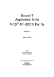
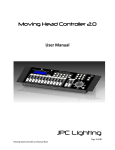
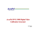
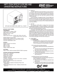
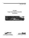
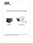
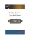
1
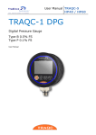
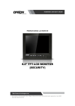
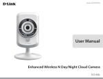
Electronic Viewfinder
EVF-035W-3G
WARNING!!
Thank you for the purchase of the Alphatron EVF-035W-3G EVF Electronic Viewfinder. We
have heard a few instances of “burned in” images on the LCD panel and wanted to send
the following precautionary information to make sure this does not happen to your unit.
Caution: The LCD panel can potentially be damaged by sunlight or other bright light
sources entering the viewfinder and being intensified by the lens. To avoid damage,
simply rotate the silver ring directly behind the eyecup to engage the capping shutter and
prevent light from entering the eyepiece.
As long as you close the capping shutter, you should not have this problem.
Electronic Viewfinder
Operation Manual_v2.4
EVF-035W-3G
Contents
1. Caution .............................................................................
2. Components .....................................................................
3. Main Features ...................................................................
4. Controls & Functions ...........................................................
5. Menu Tree & Adjustment ......................................................
6. Menu Operations ...............................................................
[1] Picture .........................................................................
[2] Color ...........................................................................
[3] Marker .........................................................................
[4] Waveform & Error Check ...................................................
[5] Audio ...........................................................................
[6] Display & Set .................................................................
[7] System .........................................................................
7. Other Functions ..................................................................
8. Product Specifications .........................................................
9. Warranty Registration ..........................................................
04
06
07
08
10
15
15
16
17
18
19
20
21
22
27
28
FCC (Federal Communications Commission)
This equipment has been tested and found to comply with the limits for class A digital device, pursuant to part 15
of the FCC Rules. These limits are designed to provide reasonable protection against harmful interface when the
equipment is operated in a commercial environment.
This equipment generates, uses and can radiate radio frequency energy and if not installed and used in
accordance with the instruction manual, may cause harmful interference to radio communications. Operation of
this equipment in a residential to correct the interference at his own expense
CAUTION: Change or modifications not expressly approved by the manufacturer responsible for compliance
could void the user’s authority to operate the equipment.
Disposal of Old Electrical & Electronic Equipment
(Applicable in the European Union and other European countries with separate collection systems)
This symbol on the product or on its packing indicates that this product shall not be treated as household
waste. Instead it shall be handed over to the applicable collection point for the recycling of electrical and
electronic equipment. By ensuring this product is disposed of correctly, you will help prevent potential negative
consequence for the environment and human health, which could otherwise be caused by inappropriate waste
handling of this product. The recycling of materials will help to conserve natural resources.
Electronic Viewfinder 3
1. Caution
• Always use set voltage. (DC 6.8-12V)
• D-tap to mini XLR connection.
• All operating instructions must be read and understood before the product is operated.
These safety and operating instructions must
be kept in safe place for future reference.
• All warnings on the product and in the instructions must be observed closely.
• All operating instructions must be followed.
• Do not use attachments not recommended
by the manufacturer. Use of inadequate
attachments can result in accidents.
• This product must be operated on a power
source specified on the specification label.
• If you are not sure of the type of power supply
used in your home, consult your dealer or local
power company. For units designed to operate
on batteries or another power source, refer to
the operating instructions.
• The power cords must be routed properly
to prevent people from stepping on them or
objects from resting on them. Check the cords
at the plugs and product.
• In case of using other DC adapters instead
of the standard adapter provided by the
manufacturer, please check the proper load
capacity (or current capacity) and use an adapter with stable voltage.
• Do not overload DC outlets or extension cords.
Overloading can cause or electric shock.
• Never insert an object into the product through vents or openings. High voltage in the
product, and inserting an object can cause
electric shock and/or short internal parts. For
the same reason, do not spill water or liquid on the product.
• Do not attempt to service the product yourself.
Removing covers can expose you to high voltage and other dangerous conditions. Request a qualified service person to perform servicing.
4 Electronic Viewfinder
• If any of the following conditions occurs, unplug the power cord from the DC outlet, and request a qualified service person to perform repairs.
a. When the power cord or plug is damaged.
b. When a liquid was spilled on the product or when objects have fallen into the product.
c. When the product has been exposed to rain or water.
d. When the product does not operate properly
as described in the operating instructions.
Do not touch the controls other than those described in the operating instructions.
Improper adjustment of controls not described in the instructions can cause damage,
which often requires extensive adjustment work by a qualified technician.
e. When the product has been dropped or damaged.
f. When the product displays an abnormal condition. Any noticeable abnormality in the
product indicates that the product needs servicing.
• In case the product needs replacement parts,
make sure that the service person uses
replacement parts specified by the manufacturer,
or those with the same characteristics and
performance as the original parts. Use of
unauthorized parts can result in fire, electric
shock and/or other danger.
• Upon completion of service or repair work,
request the service technician to perform safety
checks to ensure that the product is in proper
operating condition.
1. Caution
• Unplug the power cord from the DC outlet before cleaning the product. Use a damp cloth
to clean the product. Do not use liquid cleaners
or aerosol cleaners.
• Unplug the power cord from the AC outlet if
you do not use the product for considerably
long time.
• Do not use the product near water, such as
bathtub, washbasin, kitchen sink and laundry
tub, swimming pool and in a wet basement.
• Keep the product away from direct rays of the
Sun-light.
• Do not place the product on an unstable cart,
stand, tripod or table. Placing the product on an
unstable base can cause the product to fall,
resulting in serious personal injuries as well as
damage to the product. Use only a cart, stand,
tripod, bracket or table recommended by the
manufacturer or sold with the product. When
mounting the product on a wall, be sure to
follow the manufacturer’s instruction. Use only
the mounting hardware recommended by the
manufacturer.
• When relocating the product placed on a cart, it
must be moved with the utmost care.
• Sudden stops, excessive force and uneven
floor surface can cause the product to fall from
the cart.
• The vents and other openings in the
cabinet are designed for ventilation. Do not
cover or block these vents and openings since
insufficient ventilation can cause overheating
and/or shorten the life of the product. Do not
place the product on a bed, sofa, rug or other
similar surface, since they can block ventilation
openings. This product is not designed for
built-in installation; do not place the product
in an enclosed place such as a bookcase or rack,
unless proper ventilation is provided or the manufacturer’s instructions are followed.
• The LCD panel used in this product is made of glass. Therefore, it can break when the product is dropped or applied with impact. Be careful not to be injured by broken glass pieces in case the LCD panel breaks.
• Keep the product away from heat sources such as radiators, heaters, stoves and other heat
generating products (including amplifiers).
• Risk of explosion if battery is replaced by and incorrect type.
Dispose of used batteries according to the instructions.
• The magnification lens in the viewfinder may also magnify tiny dusts on the LCD screen which may look like defects of the LCD panel. Please wipe out or blow off the dusts on the screen before using the EVF-035W-3G.
• To avoid scratches on the LCD screen please only blow off the dust and don’t use a cloth or fingers to clean the screen.
Electronic Viewfinder 5
2. Components
EVF-035W-3G
Camera Mount x 2
D-Tap Cable
Operation Manual
Operation Manual_v 1.0
EVF-035W-3G
DC Power Adapter (Option)
6 Electronic Viewfinder
AC Power Cord (Option)
3. Main Features
EVF-035W-3G Monitor contains the following features:
• SDI signal compatibility
- This product is compatible with various SDI
signals - SD/HD/3G(A/B)-SDI 480i, 576i, 1080i,
1080p, 1080psf
• HDMI signal compatibility
- Supports HDMI(w/ HDCP) input is available without any other accessory.
• HDMI To HDMI Active Loop Throughout
- Supports HDMI-To-HDMI Active Loop Throughout function.
• Compact and powerful
- Compact size for best space utilization and powerful features that requires no other accessories
• Wide Screen / Wide Viewing Angle
• Pixel To Pixel/Zoom mode
- Used to display the original image resolution
without scaling to match a certain resolution
or an aspect ratio.
- Select ‘Pixel to pixel’ to display unscaled
images, and select ‘Zoom’ to enlarge the
original image.
- Zoom Scroll Function (Left/Right,Top/Bottom)
• Power
- Basically, the product is powered by normal
DC source.
- The product can be battery-powered.
* DC 6.8V ~ 12V
* D-tap to mini XLR connection.
• Additional features
- 3 Camera Mounting Holes, Luminance of 500cd/m2, Contrast Ratio of 1000 : 1, OSD user interface
• Rotary Control
- Easy to adjust user configuration using the
Rotary control on the left side of the viewfinder.
• BLUE ONLY/MONO/Focus Assist/H/V Delay
Function
• Range Error/Luma(Y’) Zone Check (Color/
Zebra Type) Function
• Internal Pattern Generator (0~100% Gray/
ColorBar+Pluge)
• Markers & Safety Areas
- Center Marker, Safety Area Marker, Aspect
Marker, Display Size(Scan)
• HDMI-SDI Active Loop Through-out
• Waveform & Vectorscope Functions
Electronic Viewfinder 7
4. Control & Functions
EVF-035W-3G
POWER
LED
CAMERA MOUNT
MAGNET
POWER
BUTTON
SUN HOOD
FOCUSING
WHEEL
EYECUP
SHUTTER
F1
F3
CONTROL
PART
F2
F4
SHUTTER
WHEEL
UP/DOWN
ENTER
FOCUSING
WHEEL
BATTERY
COVER
I/O PORT
CAMERA
MOUNT
BATTERY
LOCK
DEBUG
SDI IN/OUT
8 Electronic Viewfinder
HDMI IN/OUT
CALIBRATION
PGM
(Firmware Update)
LOCK
BUTTON
CAMERA
MOUNT
EXTERNAL
POWER
4. Control & Functions
SIDE
• [F1](SCAN) Button
- This Functions button is used to activate the feature selected in “DISPLAY & SET – F1 Key” menu.
- Default setting of F1 Button is Scan Mode.
• [F2](ASPECT) Button
- This Functions button is used to activate the feature selected in “DISPLAY & SET – F2 Key” menu.
- Default setting of F2 Button is Aspect.
• [F3](MARKER) Button
- This Functions button is used to activate the feature selected in “DISPLAY & SET – F3 Key” menu.
- Default setting of F3 Button is Marker Enable.
• [F4](L(Y’)ZoneCheck) Button
- This Functions button is used to activate the feature selected in “DISPLAY & SET – F4 Key” menu.
- Default setting of F4 Button is L(Y’)Zone Check.
• [MENU<EXIT>/SOURCE] Button
- Press the button for less than 2 seconds to activate the main OSD menu.
- Used to return from sub menu to main menu.
- Press the button for more than 2 seconds to change the Input Signal. (SDI <--> HDMI)
(SDI, HDMI)
BOTTOM/REAR
• [Debug] Phone Jack
- Factory uses only.
• [PGM] USB Port
- This terminal is for firmware upgrade or color calibration by using the Tool made by TVLogic.
• [SDI-IN] (BNC)
- Signal input terminal for SD/HD SDI.
• [SDI-OUT] (BNC)
- SD/HD-SDI Signal Output which is input through [SDI-IN] terminal.
• [HDMI] IN
- Signal input terminal for HDMI signal.
• [HDMI] OUT
- Signal output terminal for HDMI signal.
• BATTERY IN
- Battery Power Input : DC 6.8 ~12V
* Rated Power Input : DC 6.8 ~ 18V
* D-Tap to mini XLR connection.
• DC POWER IN (Mini XLR 4P)
- DC power input terminal for DC 12V.
• [UP/DOWN/ENTER] Rotary Control
- When OSD menu is inactivated, press the Rotary Control to adjust the value of Brightness, Contrast, Chroma or Aperture.
- Also the Rotary Control is used to decrease or increase the value of the selected feature.
<Warning!!>
When using the product make sure to ground
the product before connecting the input
signal line. The unit may not operate properly
if the input line is connected before the GND is
connected.
Electronic Viewfinder 9
5. Menu Tree & Adjustment
[1] Menu Structure
[3] Menu Control Sequence
• OSD(On-Screen Display) Menu helps you use various functions.
• This Picture is the menu structure for
EVF-035W-3G
PICTURE
Brightness
Contrast
Chroma
Aperture
Scan Mode
Aspect
3G Format
DSLR Camera
DSLR Scale
Rotary Lock
0
0
0
0
Over
16:9
Normal
CANON 5D/7D
Playback
Unlock
[2] Menu Control
• User may control various functions using MENU button and the Rotary Control
on the side of the monitor.
10 Electronic Viewfinder
1. Press MENU button to activate the OSD menu.
2. Move to a desired menu by rotating the rotary
control.
3. Press the Rotary Control to select a menu and move to select a sub-menu by rotating
the Rotary Control.
4. Press the Rotary Control to select the desired
sub menu. (The selected sub-menu will be
highlighted)
5. Press ENTER button or MENU button to
save the new value after adjusting the value
by rotating the Rotary Control.
6. Press MENU button to return to previous menu and if there is no previous menu, the OSD menu will be removed from the screen.
5. Menu Tree & Adjustment
[4] Menu Tree
PICTURE
Brightness
COLOR
Color Temp
3200K
5600K
6500K
9300K
User1
User2
User3
-100 ~ +100
Contrast
-100 ~ +100
Chroma
50 ~ +50
Gain Red
-128 ~ +127
Aperture (Sharpness)
25 ~ +25
Gain Green
-128 ~ +127
Gain Blue
-128 ~ +127
Scan Mode
Zero
Over
Pixel To Pixel
User
Bias Red
-128 ~ +127
Bias Green
-128 ~ +127
Aspect
16:9
4:3
2.35:1
1.85:1
15:9
16:10
Auto
3G Format
Normal
A444 10B_YCbCr
A444 10B_RGB
A444 12B_YCbCr
Bias Blue
A444 12B_RGB
A422 12B_YCbCr
B444 10/12B_YCbCr
B444 10/12B_RGB
B444 12B_YCbCr
B444 10B_YCbCr/P
DSLR Camera
CADNON 5D/7D
SONY A77
NIKON D7000
NIKON D4/D800
DSLR Scale
Playback
Live/REC Full
Live/REC 16:9
Rotary Lock
Unlock
Lock
Color Copy
-128 ~ +127
3200K
5600K
6500K
9300K
User1
User2
User3
Electronic Viewfinder 11
5. Menu Tree & Adjustment
[4] Menu Tree
MARKER
Marker Enable
Off
On
Marker Color
White
Gray
Black
Red
Green
Blue
Marker Type
Off
16:9
4:3
4:3 ON AIR
15:9
14:9
13:9
1.85:1
2.35:1
1.85:1 & 4:3
User
Marker Thickness
1~6
Center Marker
Off
On
User Marker H1
1~960
Safety Area
Off
80%
85%
88%
90%
93%
100%
EBU Action 16:9
EBU Graphic 16:9
EBU Action 14:9
EBU Graphic 14:9
EBU Action 4:3
EBU Graphic 4:3
User Marker H2
1~960
Fit Marker
Off
On
User Marker V1
1~640
Off
1~7
User Marker V2
Marker Mat
12 Electronic Viewfinder
1~640
5. Menu Tree & Adjustment
[4] Menu Tree
WAVEFORM & ERROR CHECK
AUDIO
L(Y’)Zone Check
Off
Color
Zebra
Level Meter
Off
16CH Hor
16CH Ver
L(Y’)Zone Adjust
0 ~ 100
Lv Meter Disp
Pair
Group
Range Error
Off
On
Lv Meter Ref
-18dB
-20dB
Y’ Max
0 ~ 255
Lv Meter Size
Small
Large
Y’ Min
0 ~ 255
Peak Decay Time
0 ~ 100
C Max
0 ~ 255
C Min
0 ~ 255
Y’ Pic Blink
Off
On
C Pic Blink
Off
On
Off
Waveform
Waveform
Vector
Waveform Wide 1
Waveform Wide 2
W/F itensity
Trans
W/F Trans
Opaque
Trans
Electronic Viewfinder 13
5. Menu Tree & Adjustment
[4] Menu Tree
DISPLAY & SET
SYSTEM
System Default
No
Yes
RS-232 Type
Upgrade
Calibration
Back Light
0 ~ 100
HDMI To SDI
Off
On
Int Pattern
Off
Color + Pluge
Gray 0% ~ 100%
FPGA :
MCU :
Time Code
Off
VITC
LTC
Focus Assist
Off
Mono On
Color On
F/A Color
Red
Green
Blue
F/A Level
0 ~ 100%
F1 Key
F2 Key
F3 Key
F4 Key
14 Electronic Viewfinder
Scan Mode
Aspect
Marker Enable
L(Y’)Zone Check
Range Error
Audio Level Meter
Time Code
Focus Assist
Blue Only
6. Menu Operations
[1] PICTURE
• 3G Format
PICTURE
Brightness
Contrast
Chroma
Aperture
Scan Mode
Aspect
3G Format
DSLR Camera
DSLR Scale
Rotary Lock
0
0
0
0
Over
16:9
Normal
CANON 5D/7D
Playback
Unlock
• Brightness
- Used to set the brightness(=offset) level from
-100 to 100.
• Contrast
- Used to set the contrast(gain) level from -100 to 100.
• Chroma
- Used to set the saturation level from -50 to 50.
• Aperture (Sharpness)
- Used to set the sharpness level from -25 to 25.
• Scan Mode
- Used to change the Scan mode. Scroll up and down the Rotary Control and the mode will be changed as the following sequence. [Over Scan] -> [Zero Scan] -> [User] ->[Pixel-
To-Pixel]
* See section “6. Other Functions -> [1] Pixel to
Pixel and [2] User Aspect” for more
information.
- Used to select 3G-SDI A/B input format
among NORMAL MODE(AUTO - A 422 10BIT_
YCbCr 50/60P), A 444 10/12BIT_YCbCr, A 444
10/12BIT_RGB, A 422 12BIT_YCbCr, B 444
10/12BIT_YCbCr, B 444 10/12BIT_RGB, B 422
12BIT_YCbCr, B 422 10BIT_YCbCr 50/60P.
- In NORMAL MODE, automatically detected
when Payload signal is contained.
• DSLR Camera
- Select the DSLR camera to be used with EVF-
035W-3G . Available models are [CANON 5D/7D], [SONY A77] and [NIKON D7000/D4/
D800].
* DSLR cameras’ screen size and aspect ratio of Live / Record / Playback modes vary according to their manufacturer.
• DSLR SCALE (HDMI Format Only)
- This is a special function for CANON/NIKON/
SONY DSLR cameras.
- Used to scale the image with different
resolution as to the operation mode(Playback, Live/REC Full, Live/REC 16:9) of the camera to fullfill the screen.
* See section “7. Other Functions [7] DSLR SCALE” for more information.
• Rotary Lock
- Locks the Rotary control.
• ASPECT
- Used to change Aspect Ratio.
- The Aspect Modes are changed as the following sequence. : 4:3, 16:9, 15:9, 1.85:1, 2.35:1
- When the original Aspect ratio of the Input Signal is 16:9, the Aspect Mode is fixed as 16:9.
Electronic Viewfinder 15
6. Menu Operations
[2] COLOR
• Color Copy
COLOR
Color Temp
Gain Red
Gain Green
Gain Blue
Bias Red
Bias Green
Bias Blue
Color Copy
6500K
0
0
0
0
0
0
6500K
• Color Temp.
- Controls color temperature and allows instant
access to preset color temperature settings.
- Available color temperatures are 3200K, 5600K, 6500K, 9300K and User 1/2/3.
- In User 1/2/3 modes, user can define custom
RGB GAIN and BIAS (=Offset) values.
• Gain Red/Green/Blue
- Used to set R/G/B Gain(or Picture, Contrast)
level from -128 to 127.
# Only available in User 1/2/3 mode.
• Bias Red/Green/Blue
- Used to set R/G/B Bias(or Offset, mainly affects on Black level) from -127 to 127.
# Only available in User 1/2/3 mode.
16 Electronic Viewfinder
- Used to copy the R/G/B Gain value of pre stored color temperature settings.
- In User mode, find and select the color
temperature and press Enter button to copy
and apply the Gain value to GAIN RED, GAIN
GREEN, GAIN BLUE.
# Only available in User 1/2/3 mode.
6. Menu Operations
[3] MARKER
• Fit Marker
MARKER
Marker Enable
Marker Type
Center Marker
Safety Area
Fit Marker
Marker Mat
Marker Color
Thickness
User Marker H1
User Marker H2
User Marker V1
User Marker V2
Off
Off
Off
Off
Off
Off
White
1
1
960
1
640
- Used to activate or inactivate the Fit Marker function.
- When the Marker type is selected in the Marker menu, a border line of the Safety Area will be displayed inside the Marker. Images below show the difference between Fit Marker ON and OFF.
• Marker Mat
- Used to set the darkeness level outside of the
MARKER area from OFF(transparent) to 7(Black).
- The bigger the value, the darker the color.
• Marker Color
• Marker Enable
- Used to activate the Marker function.
- Available marker types are OFF, 16:9, 4:3, 4:3
ON AIR, 15:9, 14:9, 13:9, 1.85:1, 2.35:1, 1.85:1 &
4:3 and USER.
• Marker Type
- Used to select the marker type.
- Available marker types are OFF, 16:9, 4:3, 4:3 ON AIR, 15:9, 14:9, 13:9, 1.85:1, 2.35:1, 1.85:1 & 4:3 and USER.
• Center Marker
- Displays the Center Marker on the screen.
• Safety Area
- Used to select to display and controls the size and availability of the Safety Area.
- Available sizes are 80%, 85%, 88%, 90%, 93%, 100%, EBU ACTION 16:9, EBU GRAPHIC 16:9,
EBU ACTION 14:9, EBU GRAPHIC 14:9, EBU ACTION 4:3 and EBU GRAPHIC 4:3.
- Used to set the color of the MARKER lines.
- Available colors are white, gray, black, red,
green and blue.
• Thickness
- Used to set the thickness of the MARKER lines.
- Thickness level is from 1 to 7 by the pixel unit.
• USER Marker H1
- Used to set the position of the first horizontal
marker line.
- Displayed when MARKER menu is set to USER.
• USER Marker H2
- Used to set the position of the second
horizontal marker line.
- Displayed when MARKER menu is set to USER.
• USER Marker V1
- Used to set the position of the first vertical
marker line.
- Displayed when MARKER menu is set to USER.
• USER Marker V2
- Used to set the position of the second vertical
marker line.
- Displayed when MARKER menu is set to USER.
MARKER
: 4:3
SAFETY AREA : 90%
FIT MARKER : OFF
MARKER
: 4:3
SAFETY AREA : 90%
FIT MARKER : ON
Electronic Viewfinder 17
6. Menu Operations
[4] WAVEFORM & ERROR CHECK
WAVEFORM / ERROR CHECK
L(Y’)Zone Check
L(Y’)Zone Adj
Range Error
Y’ Max
Y’ Min
C Max
C Min
Y’ Pic Blink
C Pic Blink
Waveform
W/F Intensity
W/F Trans
Off
75%
Off
255
0
255
0
Off
Off
Off
0
Opaque
• L (Y’) Zone Check (Luma Zone Check)
- Displays the Luma(Y’) level of the input image with specific colors.
- Each pixel’s Y’ is analyzed and changed to a specific color according to the Index on the right side of the screen.
* See section “6. Other Function [3] L(Y’)Zone Check” for more information.
- When a pixel’s Y’ level is under 0%(16), the color /diagonal line will be colored Green.
- When the pixel’s Y’ level is over 100%(235), the color / diagonal line will be colored Red.
- When the Y’ level of a pixel is between 0~100%, the pixel is displayed with Gray, except for selected Luma Zone.
- A 5% zone of the selected Y’ level will be colored Pink(5%) and ±10% will be colored Yellow(-10% from Pink) and Cyan(+10% from Pink).
• L (Y’) Zone Adj. (Luma Zone Adjust)
- Used to set the Y’ level to be colored Yellow, Pink and Cyan simply by scrolling the Rotary Control.
- Available values are 0 ~ 100%.
• Range Error
- Used to set whether or not to activate Y MAX, Y MIN, C MAX, C MIN, Y PICTURE BLINK and C
PICTURE BLINK functions.
- The values of Y MAX, Y MIN, C MAX, C MIN are indicated in WaveForm/VECTOR.
- If [Y PICTURE BLINK] or [C PICTURE BLINK] is enabled, the section of image that exceeds the selected values of Y MAX, Y MIN, C MAX and C MIN shall blink.
* See section “6. Other Function [5] Range Error” for more information.
• Y’ Max
- Used to set the maximum luma(Y’) level from 0 to 255.
- Pixels with values exceeding the max Y’ level will blink in the screen.
• Y’ Min
- Used to set the minimum luma(Y’) level from 0 to 255.
- Pixels with values exceeding the min Y’ level will blink in the screen.
• C Max
- Used to set the maximum chroma(C’) level from 0 to 255.
- Pixels with values exceeding the max C’ level will blink in the screen.
• C Min
- Used to set the minimum chroma(C’) level from 0 to 255.
- Pixels with values exceeding the min C’ level will blink in the screen.
• Y Picture Blink
- Used to set whether or not to blink pixels with values exceeding Y MAX and Y MIN. • C Picture Blink
- Used to set whether or not to blink pixels with values exceeding C MAX and C MIN.
18 Electronic Viewfinder
6. Menu Operations
[4] WAVEFORM & ERROR CHECK
[5] AUDIO
• Waveform
- Adjust Waveform and Vectorscope functions.
- Activates in order of : Off, Waveform, Vector,
Waveform Wide 1, Waveform Wide 2.
AUDIO
Level Meter
Lv Meter Disp
Lv Meter Ref
Lv Meter Size
Peak Decay Time
Off
Pair
-18dB
Small
0
• Level Meter
<Waveform Wide 1>
- Used to set the Level Meter for the embedded audio.
- Available options are OFF, 16 CH(HOR.) and 16 CH(VER.)
* 16 CH(HOR.) : Displays 8 channels on top left and 8 channels on top right of the screen horizontally.
* 16 CH(VER.) : Displays 8 channels on center left and 8 channels on top right of the screen vertically.
• Lv Meter Disp (Level Meter Display)
- Used to set the display method for audio level meter.
- Available modes are GROUP and PAIR.
<Waveform Wide 2>
• W/F Intensity
- Controls the brightness of the WAVEFORM/
VECTOR display.
- Available values are between 0 ~ 30. The
higher the number the brighter the waveform
will be.
• W/F Trans
- Controls the transparency level of the
WAVEFORM/VECTOR.
- Available values are OPAQUE and TRANS.
• Lv Meter Ref (Level Meter Reference)
- Display the default audio level meter value.
Available options are -18dB and -20dB.
- Audio level meter within selected value turns to green and exceeded audio level is displayed in yellow. Audio level exceeding -4dB is displayed in red.
• Level Meter Size
- Used to control the size of the audio level
meters.
- Available options are NORMAL and LAGRE.
• Peak Decay Time
- Sets the reduction time for max value
indication of audio signals.
- Control range is from MIN 0 to MAX 100. - Bigger number means a longer display time for max value.
Electronic Viewfinder 19
6. Menu Operations
[6] DISPLAY & SET
• F/A COLOR
DISPLAY & SET
System Defauit
Back Light
Int Patern
Time Code
Focus Assist
F/A Color
F/A Level
F1 Key
F2 Key
F3 Key
F4 Key
No
0
Off
Off
Off
Red
0%
ScanMode
Aspect
Marker Enable
L(Y‘)ZoneCheck
• System Default
- Used to initialize OSD values to factory default.
• Back Light
- Used to indicate the backlight level.
- In case of System Default, the value returns to
factory default(after color calibration).
- Available values are from 0 to 100.
• Int Pattern (Internal Pattern)
- Generates ColorBar, Pluge and Grayscale
Pattern internally.
- Selectable range for Gray Pattern is from 0% to 100% with 5% increment.
* See section “7. Other Functions -> [6] Iternal
Pattern” for more information.
• Time Code
- Used to display the Time Code.
- Available modes are VITC, LTC and OFF.
• Focus Assist
- Focus Assist helps the shooters to easily find out the exact area in the picture with good
focus, simply by adding colors on the shape or boundaries of the object in the picture.
- Available modes are Mono and Color.
* See section “7. Other Functions -> [4] Focus Assist” for more information.
20 Electronic Viewfinder
- Used to select a color for FOCUS ASSIST among red, green and blue.
• F/A LEVEL
- Used to set the edge difference value between the edges in an image.
- Available values are from 0 to 100. Larger value means more sophisticated detail detection.
- Designated color is displayed when the difference of the edges exceeds the previously set value.
- This feature is available only when the FOCUS ASSIST mode is activated.
• F1 Key
- User can select the function for [F1] Key.
- Selectable Items : Scan Mode, Aspect, Marker Enable, L(Y’) Zone Check, Range Error, Audio Level Meter, Time Code, Focus Assist, BLUE ONLY, DSLR Scale and Off.
• F2 Key
- User can select the function for [F2] Key.
- Selectable Items : Scan Mode, Aspect, Marker Enable, L(Y’) Zone Check, Range Error, Audio Level Meter, Time Code, Focus Assist, BLUE ONLY, DSLR Scale and Off.
• F3 Key
- User can select the function for [F3] Key.
- Selectable Items : Scan Mode, Aspect, Marker Enable, L(Y’) Zone Check, Range Error, Audio Level Meter, Time Code, Focus Assist, BLUE ONLY, DSLR Scale and Off.
• F4 Key
- User can select the function for [F4] Key.
- Selectable Items : Scan Mode, Aspect, Marker Enable, L(Y’) Zone Check, Range Error, Audio Level Meter, Time Code, Focus Assist, BLUE ONLY, DSLR Scale and Off.
6. Menu Operations
[7] SYSTEM
SYSTEM
RS-232 Type
HDMI To SDI
FPGA : 0.1
Upgrade
Off
MCU : 0.1
• RS-232 Type
- Choose between Firmware Upgrade or Calibration with RS-232(USB) terminal.
- When Calibration is selected the screen is changed to white. To return to normal screen mode, choose upgrade mode.
• HDMI To SDI
- Select SDI output teminal Singal.
- When it is "ON" HDMI input signal is output to SDI terminal.
- When it is "OFF" SDI input signal is output to SDI terminal.
- Avilable HDMI support signal formats are 480i/p, 576i/p, 720 50p/60p, 1080 60p/50p/60i/50i/24/25/30p
*This function is not supported when HDCP Key embedded to HDMI signal to prevent
illegal copying. (Tuned to the Off mode
automatically.)
• Displays FPGA, MCU and Calibration information.
Electronic Viewfinder 21
7. Other Functions
[1] Pixel to Pixel
• EVF-035W-3G provides pixel count information using Pixel to Pixel mode.
Select [Scan] mode in the DISPLAY & SET menu or set the Scan mode to function Key to activate the[Pixel To Pixel] mode.
• After activation of [Pixel To Pixel] mode, use the Rotary Control to move the position before the message window disappears.
• If the message window disappears, repositioning menu is not available. Then activate the [Pixel To Pixel] mode again and adjust the position by using the Rotary Control.
• Available range: H position 0~10 , V potion 0~10
22 Electronic Viewfinder
[2] User Scan
• The EVF-035W-3G can adjust the Scan Size in the User Scan Mode.
• Select [User] mode in the DISPLAY & SET menu or set the Aspect to function Key to activate the[User] mode.
• After activation of [User] mode, use the Rotary Control to move the position and adjust the size before the message window disappears.
• If the message window disappears, resizing menu is not available. Then activate the [User] mode again and adjust the position and size by using the Rotary Control.
• Available range: H Size 480~960 , V Size 320 ~ 640
7. Other Functions
[3] Luma(Y’) Zone Check
■ Color Pattern Type
■ Zebra Pattern Type
• Displays the Luma(Y’) level of the input image
in colors.
• Displays the pixels with designated Luma(Y’)
levels with zebra pattern.
• Y’ ≥ 100% : Pixels with higher Y’ level than 100
turn to red.
• Y’ ≥ 100%: Pixels with Y’ level over 100% turn
to red diagonal line.
• Y’ ≤ 0% : Pixels with lower Y’ level than 0 turn
to green.
• Y’ ≤ 0% : Pixels with Y’ level under 0% turn to
green diagonal line.
• Pixels with Y’ levels designated by the user are
displayed as following colors - yellow, pink, cyan.
• User defined Y’ levels are displayed as black
diagonal line.
• Factory Default Y’ (Border line between pink
and yellow) level is 75% and pink color is
assigned to pixels with Y’ level from 70% to 75%.
• Factory Default Y’ level is 70% and the pixels
with Y’ level from 65% to 75% is displayed
with zebra pattern
• Yellow color is assigned to pixels with Y’ level
from 75% to 85%, and Cyan from 60% to 70%.
• Pixels with 10% of Y’ level is displayed as black
diagonal line.
• This function is designed for better
performance in setting the exposure of
lighting when shooting with vDSLR cameras.
• This function is designed for better
performance in setting the exposure of
lighting when shooting with vDSLR cameras.
<Luma Zone Check OFF>
<Luma Zone Check ON_Zebra Pattern Type>
<Luma Zone Check ON_Color Pattern Type>
Electronic Viewfinder 23
7. Other Functions
[4] Focus Assist
• Focus Assist function assigns a color to the
pixels in the shape or boundary area of the
image to inform the user to make the best
focus.
• With this function, user can easily differenciate
the focused area from out-focused area
especially shooting with shallow depth of field.
• Available types are [Mono] and [Color] types.
* [Mono] : Background image is mono type.
* [Color] : Background image is original color type.
[5] Range Error
• Pixels with Y’ or C’ levels exceeding the
designated levels of Y MAX, Y MIN, C MAX and C MIN shall blink.
• Analyzes the input signal’s Luma(Y’) and chroma information(C’) and if the input signal exceeds the designated minimum value and maximum value, the pixel shall blink. This function is to help the user to easily find out any unwanted level of signals and for better exposure setting.
• When you activate the Focus assist with hot key, press the Knob button before the information window (left bottom) to disappear. Then Focus Assist level adjustment window
appears and the Foucs Assist level can be
adjusted with the Knob button.
<Range Error OFF>
<Focus Assist ON>
<Range Error ON>
<Focus Assist ON>
24 Electronic Viewfinder
7. Other Functions
[6] Internal Pattern
• Displays internally generated test patterns.
• The pattern consists of ColorBar and Pluge+
Grayscale Patterns. Full screen colors of various
gray levels(0~100%) are also embedded.
<Color Bar + Pluge Pattern>
<Gray Pattern>
Electronic Viewfinder 25
7. Other Functions
[7] DSLR Scale
• This function is designed for some DSLR
cameras(Canon 5D, 7D and Nikon D7000, D4/D800) that output different resolution from the operation mode (Playback, Live/REC Full, Live/REC 16:9).
• Select the Camera model in the [Picture]-
[DSLR Camera] menu.
■ CANON
• In StandBy mode of Canon 5D Mark II, 1080i of
HD resolution is indicated. However, real output
resolution is 1620x1080 so blank area is
displayed on the screen because the 16:9 aspect
ratio is not realized.
• In this case, use DSLR SCALE function to enlarge
the 1620x1080 image and display full screen.
• In Recording mode of CANON 5D Mark II, the
output resolution is SD(480p).
• Although it is SD, the real output resolution is
640x390 not 720x480.
■ NIKON (D7000)
• In StandBy/Record mode of NIKON, actual
resolution of the output signal from HDMI
terminal is 952x634, failing to display 16:9
aspect ratio and making marginal blank area.
Activating DSLR SCALE function will scale the
952x634 raster image to fill the full screen.
■ NIKON (D4/D800)
• In StandBy/Record mode of NIKON(D4/D800), actual resolution of the output signal from HDMI terminal is 1440x810/960x540(StandBy/
Record).
Activating DSLR SCALE function will scale the
1440x810/960x540 raster image to fill the full screen.
■ SONY
• In StandBy/Record mode of SONY, actual
resolution of the output signal from HDMI
terminal is 1440x810.
Activating DSLR SCALE function will scale the
1440x810 raster image to fill the full screen.
• DSLR SCALE function scales the 640×390 image
to 960x640(panel resolution) and display full
screen.
※Note
1. When you compare the circle chart or the
camera shooting chart with DSLR connected
monitor(HDMI) and HDMI to SDI Conversion
connected monitor, The function of Live/Rec
16:9 mode should be selected to compare
circle and it is equal to its actual. If the circle is
compared in Live/Rec Full mode, the output of
the circle is deformed.
2. Both EVF-035W-3G connected DSLR
and EVF-035W-3G connected HDMI to SDI
Conversion should be compared to cirlce in
Zeroscan mode. It is deformed if user selects in
Overscan and Underscan mode.
<DSLR Scale OFF>
<DSLR Scale ON>
26 Electronic Viewfinder
8. Product Specifications
EVF-035W-3G
LCD
Input Connector
Output
Input Signal
Size
3.54”
Resolution
960 X 640
Pixel Pitch
0.078(H) X 0.078(W) mm
Color Depth
24-bits (R8, G8, B8)
Viewing Angle
160(H) / 160 (V)
Luminance of white
Contrast Ratio
500cd/㎡
1000 : 1
Display Area
74.88(H) X 49.92(V) mm
1 X BNC
SDI Channel Input
1 X HDMI
HDMI Input
1 X BNC
SDI Channel (Active Loop Through Out)
1 X HDMI
HDMI Channel (Active Loop Through Out)
3G-SDI
2.970Gbps
HD-SDI
1.485Gbps
SD-SDI
270 Mbps
HDMI
480i/480p/720p/1080i & VESA/IBM Modes
SMPTE-425M-A/B
1080p(60/59.94/50/30/29.97/25/24/23.98/30sF/29.97sF/25sF/24sF/23.98sF)
1080i(60/59.94/50)
SMPTE-274M
SDI Input Signal
Formats
1080i (60/59.94/50)
1080p (30/29.97/25/24/24sF/23.98/23.98sF)
SMPTE-296M
720p (60/59.94/50)
SMPTE-260M
1035i (60/59.94)
SMPTE-125M
480i (59.94)
ITU-R BT.656
576i (50)
Power
DC 6.8~12V
Power Consumption (Approx.)
9.6Watts(Typ.)
Operating Temperature
0℃ to 40℃ (32℉ to 104℉)
Storage Temperature
-20℃ to 60℃ (-4℉ to 140℉)
Main Body Dimensions (mm/inch)
111.39 x 83.34 x 213.08 (4.38 X 3.28 X 8.39)
Box Dimensions (mm/inch)
285 X 155 X 124 (11.22 X 6.10 X 4.88)
Weight
Net Weight : 460g / 1.01lbs Gross Weight : 840g / 1.85lbs
Basic Accessories
Manual, D-Tap Cable, Camera Mount Support x2
Optional Accessories
Adaptor + Power Cord(US/UK/EU)
* D-tap to mini XLR connection.
* The specification above may be changed without notice.
Electronic Viewfinder 27
9. Warranty Registration
Registration Warranty
Dear User,
You became the owner of the Alphatron Electronic View Finder EVF035W-3G. We advise you to register your EVF-035W-3G before using.
Direct registration at www.evf.tv/registration will give you the advantage to:
- professional assistance through authorized Technical Service Providers
Please keep this warranty card in a safe place together with your
purchase invoice!
You will receive a confirmation e-mail of your registration.
Product type: EVF-035W-3G
Serial No.:
28 Electronic Viewfinder
____________
MEMO
Electronic Viewfinder 29
MEMO
30 Electronic Viewfinder
FOR MORE INFORMATION PLEASE VISIT : www.alphatron.tv
Spoorhaven 78, 2651 AV Berkel en Rodenrijs, The Netherlands
TEL : +31 10 514 0680, FAX : +31 10 514 0699, E-mail : [email protected]