1
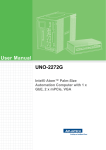
Page: 1/22
HV-AMP400FN-4+400-D
Fast High-Voltage Power Waveform Generator
for Driving Quadrupole Traps
Version 1.00
User Manual
Document version A, created on Jun-26-2014
CGC Instruments
Hübschmannstr. 18 | D–09112 Chemnitz
Tel.: +49 (371) 355 098–55
Fax: +49 (371) 355 098–60
internet: www.cgc-instruments.com
e–mail: [email protected]
Page: 2/22
HV-AMP400FN-4+400-D
Contents
Safety Information ..........................................................4
Technical Data................................................................5
Characteristics .............................................................................. 5
Output Amplifiers........................................................................... 5
Offset Amplifier.............................................................................. 5
Security ......................................................................................... 5
Monitoring ..................................................................................... 6
Human Interface............................................................................ 6
Power Supply ................................................................................ 6
Connectors.................................................................................... 7
General ......................................................................................... 7
Shipment Contents........................................................................ 7
Description .....................................................................9
General ......................................................................................... 9
Block diagram ............................................................................... 9
Power amplifier ........................................................................... 12
Monitoring ................................................................................... 13
Embedded safety precautions .................................................... 13
Control and Indication Elements ................................................. 14
Terminals .................................................................................... 15
Practical usage............................................................................ 17
Installation ....................................................................21
CGC Instruments
Hübschmannstr. 18 | D–09112 Chemnitz
Tel.: +49 (371) 355 098–55
Fax: +49 (371) 355 098–60
internet: www.cgc-instruments.com
e–mail: [email protected]
Page: 3/22
HV-AMP400FN-4+400-D
Figure List
Fig. 1. The block diagram of the power waveform generator. ...... 8
Fig. 2. The output connector. ...................................................... 15
Fig. 3. The front panel of the power waveform generator........... 19
Fig. 4. The rear panel of the power waveform generator. .......... 20
Table List
Tab. 1. Pin layout of the output connector. ................................. 16
Tab. 2. Monitor channel assignment........................................... 16
CGC Instruments
Hübschmannstr. 18 | D–09112 Chemnitz
Tel.: +49 (371) 355 098–55
Fax: +49 (371) 355 098–60
internet: www.cgc-instruments.com
e–mail: [email protected]
Page: 4/22
User Manual HV-AMP400FN-4+400-D: Safety Information
Safety Information
• The device may be installed and used by authorized and instructed
personnel only. Read this manual carefully before installing and using the device. Always follow the safety notes and warnings in this
manual.
• The device is designed for indoor dry laboratory use only. Before
powering the device on, the device temperature must accommodate
to the ambient temperature to avoid moisture condensation. Take
this into account when setting up the device after transporting it.
• Do not operate the device if it is damaged or not functioning properly. Never use damaged cables or accessories.
• Do not open the device case, install replacement parts, or perform
modifications to the device. There are no user serviceable parts inside.
• To avoid damage, connect the line cord to a properly wired and
grounded receptacle only. Be sure that the mains voltage and the
fuse rating match the device specification. Never operate the device
during electrical storms.
• Never use corrosive or abrasive cleaning agents or polishes, avoid
the usage of organic solvents. If necessary, clean the device with a
soft moist cloth. Make sure that the device is completely dry and
free from contaminants before powering it on.
!
!
!
!
Warning: The device produces lethal voltages. Never touch the output terminals even if the device is powered off. The device is equipped
with several protection features that eliminate the risk of contact with a
high voltage. This protection, however, may fail in case of a fault and
unexpected high voltages may be present at the terminals.
Warning: The amplifier is an electronic device that is sensitive to electrostatic electricity. While manipulating with the amplifier, the ESD
(Electro-Static Discharge) protection rules must be kept in mind.
Avoid touching the heatsink of the device if the device is running or
has just been turned off. The heatsink temperature may reach up to
60°C, you may suffer burns.
Warning: The device weighs about 25 kg. Use an appropriate carrier
when transporting and provide a stable support for its operation.
CGC Instruments
Hübschmannstr. 18 | D–09112 Chemnitz
Tel.: +49 (371) 355 098–55
Fax: +49 (371) 355 098–60
internet: www.cgc-instruments.com
e–mail: [email protected]
Page: 5/22
User Manual HV-AMP400FN-4+400-D: Technical Data
Technical Data
Characteristics
•
•
•
•
•
four-channel fast high-voltage amplifier for light capacitive loads
offset amplifier
digitally-controlled waveform generator
dc accuracy, ultra-low temperature coefficient of the gain
19" case
Output Amplifiers
•
•
•
•
•
•
•
•
•
four channels
output voltage: ±400 V
output current: >25 mA continuous, >50 mA pulsed
signal bandwidth: DC..10 MHz ±10%, DC..100 kHz ±1%
power bandwidth:
limited by the output current, >100 kHz with a load of 100 pF
slew rate: about 250 V/μs, dependent on the capacitive load
output noise:
200 mVp–p typ. (DC to 500 MHz)
13 mVp–p typ. (DC to 100 kHz)
amplification accuracy at low frequencies: < 600 ppm (200 ppm typ.)
temperature coefficient of the gain at low frequencies:
< 10 ppm/K (5 ppm/K typ.)
Offset Amplifier
•
•
•
•
output voltage: ±400 V
output current: >15 mA continuous
signal bandwidth: DC..100 Hz (–3dB)
slew rate: about 1 V/ms
Security
• interlock loop: BNC socket, short circuit enables the amplifier
• overcurrent protection: output current limiter
• overtemperature protection:
temperature sensors at the heatsink
(shutdown temperature programmable)
• voltage: supply voltage supervision
CGC Instruments
Hübschmannstr. 18 | D–09112 Chemnitz
Tel.: +49 (371) 355 098–55
Fax: +49 (371) 355 098–60
internet: www.cgc-instruments.com
e–mail: [email protected]
Page: 6/22
User Manual HV-AMP400FN-4+400-D: Technical Data
Monitoring
• monitor outputs:
four 50 Ω BNC sockets, output impedance: 50 Ω
attenuation –1:1000 w/o load, –1:2000 at load of 50 Ω
(signals are inverted with respect to the main outputs)
accuracy at low frequencies: < 0.2% (0.1% typ.)
temperature coefficient of the attenuation at low frequencies:
< 50 ppm/K (20 ppm/K typ.)
signal bandwidth: DC..10 MHz ±10%, DC..100 kHz ±1%
• LED: Power On, color: green
• supply voltages
• temperature at the heatsink, the chassis plate, and the CPU
• status indicators over the LCD:
Power Supply Activated
Interlock
Fan Failure
Amplifier Overheated
Human Interface
• monochrome LCD display 128x64 pixel
pixel size: 0.5 mm
pixel color: yellow, background: blue
background illumination: white LED
• keypad: 5 keys: 4x direction + 1x "enter"
• rotary encoder: 24 positions per revolution, integrated press button
• optional external shutdown button via the interlock loop
Power Supply
• rated voltage: 230 V ±10%, 50 Hz
• inrush current: limited to 3.6 A
• power consumption:
standby (amplifier deactivated): 37 VA
amplifier activated but without signal: 110 VA
maximum (sine 800 Vp–p at 100 kHz): 160 VA
peak: 1.1 kVA
• main fuse: T 1.25 A (slow acting), size ø5x20 mm
• mains connection:
IEC inlet with EMC filter and integrated fuse holder
CGC Instruments
Hübschmannstr. 18 | D–09112 Chemnitz
Tel.: +49 (371) 355 098–55
Fax: +49 (371) 355 098–60
internet: www.cgc-instruments.com
e–mail: [email protected]
Page: 7/22
User Manual HV-AMP400FN-4+400-D: Technical Data
Connectors
• data link: USB receptacle series B, location: front panel
• monitor outputs, trigger inputs and outputs:
each set: four 50 Ω BNC sockets, location: front panel
• output: Amphenol MS3102R22-18S
high-voltage panel receptacle with 8 female sockets
location: rear panel
• interlock loop: 50 Ω BNC socket, location: rear panel
• mains input: IEC inlet, location: rear panel
General
• 6 U 19" bench-top case:
height: 266 mm, width: 448 mm, depth: 380 mm,
total depth with heatsink, fans, and handles: 488 mm,
total height with case feet: 280 mm,
side panels: black lacquered,
cover and bottom panels: silver gray painted,
front and rear panels: clear anodized
• heatsink:
black anodized extruded aluminum profile at the rear panel
• forced cooling:
two 120 mm fans at the heatsink,
temperature-dependent regulation of the fan speed,
monitored fan operation, warning on fan failures
• operating temperature range: +10..+40°C
• weight: 23 kg
• cleaning: use moist cloth only, avoid use of organic solvents
Shipment Contents
•
•
•
•
•
power waveform generator HV-AMP400FN-4+400-D
line cord (universal IEC mains lead, length 1.8 m)
output cable with an Amphenol MS3106F22-18P connector
control and diagnostic software
user manuals
CGC Instruments
Hübschmannstr. 18 | D–09112 Chemnitz
Tel.: +49 (371) 355 098–55
Fax: +49 (371) 355 098–60
internet: www.cgc-instruments.com
e–mail: [email protected]
CGC Instruments
Hübschmannstr. 18 | D–09112 Chemnitz
Tel.: +49 (371) 355 098–55
Fax: +49 (371) 355 098–60
Fig. 1. The block diagram of the power waveform generator.
User Manual HV-AMP400FN-4+400-D: Technical Data
ϑ
Page: 8/22
internet: www.cgc-instruments.com
e–mail: [email protected]
Page: 9/22
User Manual HV-AMP400FN-4+400-D: Description
Description
General
The power waveform generator is a combination of several highvoltage power amplifiers and a programmable digitally-controlled
waveform generator. It is fit into a metallic 19" case, the front panel is
shown in Figure 3.
The waveform generator is described in an individual manual. The
waveform generator contains beside its intrinsic function also control
and monitoring circuits of the power amplifier. The function of them is
briefly described in this document, for more details please consult the
manual of the waveform generator.
Block diagram
The block diagram of the device is shown in Fig. 1. The four output
voltages Out1-4 are produced by fast high-voltage amplifiers
HVA400FN. The reference potential of these end stages is the signal
HV-Gnd (symbol ). This potential is also referred to as offset voltage
and usually defines the potential in the center of the connected quadrupole trap. The maximum output voltage of each output channel is
±400 V relative to the offset voltage.
The offset voltage is defined by a dc high-voltage amplifier HVA1. This
amplifier creates the potential HV-Gnd in the range of ±400 V relative
to the output ground (symbol ). The output ground is galvanically
isolated from other circuits, thus it can be externally connected to the
vacuum chamber without any risk of ground loop.
The central circuit of the waveform generator is the FPGA (Field Programmable Gate Array). It controls the waveform digital-to-analog
converter DAC2 and the memory MRAM. To generate a waveform,
the digital data samples are read from the memory and passed to the
digital-to-analog converter where they are converted to voltages in the
range of ±10 V. The memory MRAM is a non-volatile magnetoresistive
random-access memory with a space for about 1 million data samples.
The output signal from the waveform converter DAC2 is attenuated in
the next digital-to-analog converter D-POT to the desired amplitude.
The output signal is passed directly or via an inverter to four summing
CGC Instruments
Hübschmannstr. 18 | D–09112 Chemnitz
Tel.: +49 (371) 355 098–55
Fax: +49 (371) 355 098–60
internet: www.cgc-instruments.com
e–mail: [email protected]
Page: 10/22
User Manual HV-AMP400FN-4+400-D: Description
amplifiers. They create the control voltages for the output amplifiers
HVA400FN from the waveform signal and from the extraction voltages
produced by the digital-to-analog converters DAC3-6.
During waveform generation, the converters DAC3-6 are reset, thus
do not contribute to the output voltages. An extraction starts when the
output waveform finishes, i.e. he signal reaches zero voltage. In this
moment, the converters DAC3-6 are switched to the previously preset
voltages. This produces defined voltage pulses at the outputs.
Similarly to the extraction converters DAC3-6, the digital-to-analog
converter DAC1 creates the control voltage for the offset amplifier
HVA1. The voltage of the offset converter DAC1 and the amplitude
controlled by the converter D-POT cannot be changed immediately by
a large step. The control hardware ensures that linear ramps are applied instead. This avoids fast voltage slopes in the output signal due
to immediate amplitude change and also unnecessary high output current of the offset amplifier HVA1.
The isolators IS1-4 transfer the digital control signals from the groundrelated levels at the FPGA to levels related to the offset voltage, i.e.
the signal HV-Gnd or to the output ground. The digital circuits are gal), i.e. to the PE
vanically connected to the frame ground (symbol
wire.
The FPGA serves also the four trigger inputs and the four trigger outputs, as well as the interlock input and the optional LED indicators. It
communicates with the central microcontroller CPU. The microcontroller implements the user interface. It controls the graphic display LCD,
reads the keypad and the rotary encoder and serves the USB or
Ethernet interface. The device can serve only one of the interface
types, the standard implementation includes the USB interface. Using
the interface, waveform data can be transferred from/to the device or
the system can be remotely controlled.
The microcontroller uses a serial bus (I²C) for the communication with
several other circuits: the PLL, the ADC1-4, and the fan controller
FanCtrl. The PLL is a time-base generator producing the clock for the
waveform generator from a quartz oscillator XO. The desired frequency is gained by a multiplication by a rational number using the
PLL (Phase-Locked Loop) technique. The analog-to-digital converters
ADC1-4 monitor the supply voltages of the device. Since two of them
(ADC3 and ADC4) are galvanically connected to the offset voltage,
i.e. to the signal HV-Gnd, the I²C bus is isolated by a bus isolator IS5.
CGC Instruments
Hübschmannstr. 18 | D–09112 Chemnitz
Tel.: +49 (371) 355 098–55
Fax: +49 (371) 355 098–60
internet: www.cgc-instruments.com
e–mail: [email protected]
Page: 11/22
User Manual HV-AMP400FN-4+400-D: Description
The fan controller FanCtrl is a microcontroller-based unit that controls
and monitors two fans at the heatsink. It measures the temperature at
the heatsink and the chassis plate in the center of the device by
means of six independent sensors. The acquired temperature values
are used to regulate the rotational speed of the fans. If any sensor
fails or the measured temperature exceeds a predefined value, the
device is shut down independently on the fan function.
The device is supplied by several precise power supply units:
PSU-LV1,2 and PSU-HV+LV1,2. The power supply units are equipped
by current limiters to avoid catastrophic damage in case of any failure.
Moreover, the high-voltage supply units providing about ±430 V for the
amplifiers can be switched on and off. The activation of the power
supply is user-selectable, the high-voltage supply can be automatically enabled when there is an active waveform output or can be permanently turned on. An opened interlock loop or any overload condition always cause a shutdown of the high-voltage power supply and
disable the waveform generation. This measure ensures that in critical
situations, no lethal voltage can be present at the outputs.
The amplifiers and the power supplies are linearly operating circuits.
The power supplies are equipped with toroidal transformers; these
produce only a weak stray magnetic field. The device does not use
any power switching circuits such as switching-mode power supplies
or class-D amplifiers. Further, the digital circuits are enclosed in metallic boxes that screen the sensitive analog circuits from the disturbing
digital signals. Thus, the emission level of electromagnetic radiation
and the conducted digital noise in the output signals are rather low. As
a result, the device should not disturb even sensitive instruments
nearby.
The digital-to-analog converters used for the waveform generation
and for the generation of the extraction pulses are fast precise converters with a resolution of 16 bits and a low temperature coefficient
(< 2 ppm/K). The amplifiers in the signal path use precise feedback
resistors with a tolerance of 0.01 % (100 ppm) and a very low temperature coefficients (< 0.2 ppm/K). The amplifiers use the autozeroing technique to optimize their dc precision. This leads to a substantial reduction of the offset and drift voltages. On the other hand,
the ac performance has been optimized by implementing dedicated
composition amplifiers to reach wide bandwidth for best precision at
higher frequencies.
CGC Instruments
Hübschmannstr. 18 | D–09112 Chemnitz
Tel.: +49 (371) 355 098–55
Fax: +49 (371) 355 098–60
internet: www.cgc-instruments.com
e–mail: [email protected]
Page: 12/22
User Manual HV-AMP400FN-4+400-D: Description
The device is controlled by two programmable circuits: the FPGA and
the CPU. By reprogramming these circuits, optional changes of the
device functionality can be easily implemented.
Power amplifier
The fast high-voltage amplifiers HVA400FN that provide four output
voltages of up to ±400 V relative to the common offset voltage ensure
a high accuracy of the output signal up to frequencies of several
100 kHz. The frequency response ranges to more than 10 MHz with a
gain tolerance of ±10%. The frequency response is flat up to more
than 100 kHz, the expected error is lower than 1%. The voltage stability is given by the used components (digital-to-analog converters,
feedback resistors, voltage references, and the amplifiers itself) and is
better than 10 ppm/K at low frequencies. At frequencies in the order of
100 kHz, the influence of stray capacitances increases, thus the
stability become worse. The exact values can be precisely determined
only by a measurement during the particular experiment.
The amplifiers HVA400FN have a slew rate of about 250 V/μs. Thus,
the full voltage transition from 0 to ±400 V during the extraction can be
finished within less than 2 μs. The slew rate also determines the
power bandwidth. The power bandwidth is the maximum frequency of
a sinusoidal signal with the full amplitude that can be produced without any limitation. The amplifiers can typically provide sinusoidal signals with the full amplitude of 400 V at frequencies up to more than
100 kHz.
In the practice, the slew rate is determined by the maximum output
current of the amplifiers. The output current has to recharge the capacitance at the output, this may affect the slew rate. The output capacitance is mainly given by the output cable and partially also by the
capacitance of the trap electrode. Thus, to reach optimal performance,
the length of the output cable should be minimized. The output connector at the rear panel is connected by 45-cm-long coaxial cables
RG-71. Generally, the external output cable should not be substantially longer than the internal connection. Also, the trap electrodes
should be carefully designed to prevent high mutual capacitances or
capacitances against the ground, i.e. against an optional shielding or
the metallic walls of the vacuum chamber.
The offset amplifier HVA1 is a precise amplifier that provides output
currents up to more than 15 mA. In a symmetrical electrode arrangeCGC Instruments
Hübschmannstr. 18 | D–09112 Chemnitz
Tel.: +49 (371) 355 098–55
Fax: +49 (371) 355 098–60
internet: www.cgc-instruments.com
e–mail: [email protected]
Page: 13/22
User Manual HV-AMP400FN-4+400-D: Description
ment with symmetrical output voltages, virtually no output current is
necessary to maintain the offset voltage. In real experiments, ions or
electrons may hit the electrodes or the isolation of the electrodes may
leak. This may cause small current fluxes that have to be compensated by the offset amplifier HVA1.
The offset voltage is buffered by a large capacitance of about 15 μF
that provides a low impedance at high frequencies. Due to the high
capacitance, the limited output current of the offset amplifier limits the
attainable slew rate to about 1 V/ms. Note that to change the offset
voltage by 800 V, i.e. for instance, from –400 V to +400 V, a time of
about 1 s is necessary.
Monitoring
To check the output signal of the amplifiers, four monitor outputs are
available. They provide an inverted, 1000-times attenuated voltage of
the corresponding output terminal, provided, they are unloaded.
Loaded by the nominal impedance of 50 Ω, the monitor terminals produce the half amplitude, i.e. have an attenuation of 2000. The frequency response of the monitor outputs is correct only at the nominal
load of 50 Ω. In this case, the frequency response is flat up to more
than 10 MHz ensuring correct signal forms even at fast transitions at
the device outputs. If the outputs are unloaded, the frequency response will depend on the length of the connected cable and may
show drop or peaking at higher frequencies. For a proper monitor output, connect an oscilloscope or another signal analyzer using well
terminated cables with a characteristic impedance of 50 Ω.
Embedded safety precautions
The device is equipped with an interlock loop that disables the signal
output if it is opened. The terminals of the interlock loop are located at
a BNC socket at the rear panel. They are typically conducted to the
control system of the vacuum setup where they are short-connected if
the vacuum pressure is sufficiently low. To implement a security push
button, the interlock loop can be additionally interrupted by a switch
with a breaking contact.
The amplifiers and their power supplies are cooled by a large heatsink
located at the rear panel of the device. The heatsink is actively cooled
by two fans. The rotational speed of the fans is controlled by the tem-
CGC Instruments
Hübschmannstr. 18 | D–09112 Chemnitz
Tel.: +49 (371) 355 098–55
Fax: +49 (371) 355 098–60
internet: www.cgc-instruments.com
e–mail: [email protected]
Page: 14/22
User Manual HV-AMP400FN-4+400-D: Description
perature of the power semiconductor devices. Thus, in the standby
state with disabled signal output, the device produces only minimal
acoustic noise, since the fan speed is rather low or the fans are completely stopped (for a detailed description of the fan controller, see the
manual of the waveform generator). With activated amplifiers and with
large output voltages at high frequencies, the heatsink temperature
increases and the fans are controlled to rotate faster. Under certain
conditions, the cooling power of the device may be insufficient and the
power semiconductor devices could overheat. This may happen if the
output is overloaded or even shorted, if the ambient temperature is
high, or if any of the fans fails. To prevent any catastrophic damage,
the power supply units and the signal generation are deactivated if the
temperatures exceed a preset level.
The device also monitors all supply voltages and shuts down if any of
the voltages is out the predefined limits. This may happen on overload
or in case of any hardware failure. This measure prevents the power
semiconductor devices from overloading and/or overheating.
Control and Indication Elements
All control elements are located on the front panel of the power waveform generator (see Fig. 3).
Using the rocker switch "Power", you can power the device on or off.
When powered on, the LED above the power switch lights green and
the display (LCD) turns on.
For controlling the operation, the device is equipped with a graphic
liquid crystal display (LCD), a set of keys (keypad) and a rotary encoder. The keys are arranged in a circle symbolizing the key function:
There are four direction keys ("left", "right", "up", and "down") and a
middle key for confirmation or selection ("enter").
The keys are used for menu navigation, for selecting dialog items, or
for changing various values. The function of the keypad in every device state is symbolized on the LCD immediately above the keypad. A
text describes the function of the middle key, alternatively just the
symbol " " is displayed showing that the middle key can be used.
Similarly, arrows show which of the keys has an influence on the operation in the current state. When a menu is active, the vertical direction keys are used to change the current selection. The right direction
key as well the middle key opens a submenu, provided it is available.
CGC Instruments
Hübschmannstr. 18 | D–09112 Chemnitz
Tel.: +49 (371) 355 098–55
Fax: +49 (371) 355 098–60
internet: www.cgc-instruments.com
e–mail: [email protected]
Page: 15/22
User Manual HV-AMP400FN-4+400-D: Description
The left direction key closes the submenu or the main menu if there
was no opened submenu. The middle key selects the menu item and
launches the corresponding action.
The rotary encoder is used to change numerical values or select
items. The function of the encoder in every device state is symbolized
on the LCD immediately above the encoder knob. In most situations,
the encoder uses an enhanced speed control. This enables you to set
precisely any desired value or rapidly make large changes, since the
value steps are proportional to the rotational speed of the encoder.
You can change the corresponding value in small steps when you rotate the encoder slowly or make large changes when you spin the encoder knob rapidly. In some situations, the encoder's push button is
used to confirm the selected value or to switch the rotary encoder
function. In such cases, the symbol " " is shown on the LCD above
the encoder knob.
For more details about the operation, see the manual of the waveform
generator.
Terminals
The output terminals are located at the connector "Output" at the rear
panel. The connector is a robust Amphenol panel receptacle
MS3102R22-18S with eight female sockets (for the pin layout, see
Fig. 2 and Tab. 1). The connection should be realized by a special set
of coaxial cables. Contact the manufacturer for available solutions.
Fig. 2. The output connector.
The figure shows the look on the male pin contacts of the cable plug.
CGC Instruments
Hübschmannstr. 18 | D–09112 Chemnitz
Tel.: +49 (371) 355 098–55
Fax: +49 (371) 355 098–60
internet: www.cgc-instruments.com
e–mail: [email protected]
Page: 16/22
User Manual HV-AMP400FN-4+400-D: Description
Note that the output terminals are not galvanically connected to the
device housing, i.e. to the PE wire. The output ground is defined by
the shielding of the output cables and should be connected to the metallic parts of the vacuum chamber in that the quadrupole system is
located.
Tab. 1. Pin layout of the output connector.
Pin
Signal
Description
A
R1-Out
positive output 1, signal
B
R1-Gnd
positive output 1, ground
C
E1-Out
negative output 1, signal
D
E1-Gnd
negative output 1, ground
E
E2-Out
negative output 2, signal
F
R2-Gnd
positive output 2, ground
G
R2-Out
positive output 2, signal
H
E2-Gnd
negative output 2, ground
For monitoring purposes, the output signals are attenuated and inverted by active attenuators and connected to the four BNC sockets
"Output Monitor" at the front panel. For the assignment of the monitor
channels to the output signals, see Tab. 2. The BNC sockets are isolated from the device housing and grounded to the output ground. If
you connect any device to the monitor outputs, take care about the
grounding. An oscilloscope equipped with a standard grounding to the
PE wire may introduce a large ground loop that can affect the purity of
the signals at the device outputs. Note that due to the inversion of the
monitor outputs, the signals have an opposite polarity compared to the
high-voltage outputs at the rear panel.
Tab. 2. Monitor channel assignment.
Channel
Output
Out1
E1
negative output 1
Out2
E2
negative output 2
Out3
R1
positive output 1
Out4
R2
positive output 2
CGC Instruments
Hübschmannstr. 18 | D–09112 Chemnitz
Description
Tel.: +49 (371) 355 098–55
Fax: +49 (371) 355 098–60
internet: www.cgc-instruments.com
e–mail: [email protected]
Page: 17/22
User Manual HV-AMP400FN-4+400-D: Description
Digital trigger signals can be connected to the BNC sockets "Trigger
Input" at the front panel. The signals should have standard TTL levels.
The four channels can be used to start the waveform generation, to
trigger the extraction, etc. The four BNC sockets "Trigger Output" at
the front panel can be used to monitor the operation of the device (for
more details, see the manual of the waveform generator). They provide signals with a standard TTL level that indicate the activity of the
waveform generation, the presence of the extraction pulse, etc. The
output impedance of the output terminals equals to 50 Ω. Thus, the
outputs can drive long coaxial cables with a characteristic impedance
of 50 Ω. The termination is required especially for longer cables. The
output load of 50 Ω causes that the output amplitude decreases from
5 V at unloaded outputs to about 2.5 V at outputs with the nominal
load. The trigger inputs and outputs are galvanically connected to the
device housing, thus to the PE wire.
The connector of the interlock loop is a BNC socket at the rear panel.
Although it is isolated from the device housing, there is no galvanic
isolation present. The connector has to be shorted to enable the device. Generally, this requires a control by an isolated relay contact. If
this is not available, the middle contact of the BNC socket can be
shorted to the device housing, i.e. to the PE wire to close the interlock
loop.
For the mains connection, an IEC inlet with an EMC filter and an integrated fuse holder is located at the rear panel. Use a standard line
cord with the universal IEC mains lead to connect the device to the
mains. To replace the fuses, remove the line cord and open the fuse
holder. Insert the new fuses, close the fuse holder, and connect the
line cord back to the IEC inlet.
Practical usage
The typical output load of the device is a linear quadrupole trap for
heavy ions or microparticles. The device produces an arbitrary waveform that is intended to be used to create the trapping potential. The
four output channels provide two pairs of ac voltages, the first pair
provides a direct signal, the second pair an inverted one. Thus, the
device acts as a 2-phase supply for a quadrupole trap consisting of
four electrodes.
CGC Instruments
Hübschmannstr. 18 | D–09112 Chemnitz
Tel.: +49 (371) 355 098–55
Fax: +49 (371) 355 098–60
internet: www.cgc-instruments.com
e–mail: [email protected]
Page: 18/22
User Manual HV-AMP400FN-4+400-D: Description
The amplitude of the four output channels is freely variable up to
400 V. Since all channels use the same waveform generator, the amplitude is the same on each output.
The offset of the output voltages determines the potential in the trap
center and is adjustable in the range of ±400 V.
The trapping can be finished by introducing an extraction phase. During this phase, the voltages at the four output channels can be set to
independently selectable values. The extraction voltages may be
again within the ±400 V margin relative to the offset voltage, i.e. the
resulting output voltage may reach ±800 V as during the waveform
generation.
CGC Instruments
Hübschmannstr. 18 | D–09112 Chemnitz
Tel.: +49 (371) 355 098–55
Fax: +49 (371) 355 098–60
internet: www.cgc-instruments.com
e–mail: [email protected]
User Manual HV-AMP400FN-4+400-D: Description
Fig. 3. The front panel of the power waveform generator.
Page: 19/22
CGC Instruments
Hübschmannstr. 18 | D–09112 Chemnitz
Tel.: +49 (371) 355 098–55
Fax: +49 (371) 355 098–60
internet: www.cgc-instruments.com
e–mail: [email protected]
User Manual HV-AMP400FN-4+400-D: Description
Fig. 4. The rear panel of the power waveform generator.
Page: 20/22
CGC Instruments
Hübschmannstr. 18 | D–09112 Chemnitz
Tel.: +49 (371) 355 098–55
Fax: +49 (371) 355 098–60
internet: www.cgc-instruments.com
e–mail: [email protected]
Page: 21/22
User Manual HV-AMP400FN-4+400-D: Installation
Installation
To install the power waveform generator, a space of at least
45 × 55 × 30 cm³ (W × D × H) on top of a stable table is required. The
device weighs about 25 kg, the supporting surface must guarantee
mechanical stability under this load. The installation area must be kept
dry and the temperature within the range specified in the section
"Technical Data". Note that significant amount of power is turned into
heat during the device operation. Avoid exposing the device to direct
sun light since this may substantially elevate the device temperature.
During operation, only the front panel of the power waveform generator must be accessible. Before installing the device in its final position,
you should install the line cord, the interlock connection, and the output cable. The device should be positioned such that the length of the
output cable can be minimized. The output cable connects the device
to the vacuum feedthrough with the terminals of the quadrupole trap.
Shorter cable implies a lower output capacitance, thus a lower output
load and a better precision at higher frequencies. The line cord is
connected to the IEC inlet on the rear panel, the interlock connection
to the BNC socket.
The heatsink at the rear panel must not be covered or obstructed during device operation, it must be provided with sufficiently cool air for
active cooling of the device. Take necessary precautions to ensure a
sufficient supply of cool air when installing the device in closed racks.
Inspect and clean the fans at the heatsink regularly. Use a vacuum
cleaner to remove dust from the fans and from the heatsink. Large
dust layers substantially lower the cooling power of the heatsink, thus
the device may overheat if the heatsink is extremely dirty. Also the
lifetime of dirty fans may be significantly shortened.
To power the device, a power mains socket with proper grounding is
required. Check the power rating of the mains socket, since the peak
power consumption of the device during the startup may be as high as
650 VA.
Before powering on the system, read the user manual carefully.
If already connected, disconnect the load and power on the device by
toggling the rocker switch "Power". The LED above the power switch
will light green and the display will turn on. Press the middle key "enter" and start the dialog box "Status Monitor" by selecting the menu
item "Monitor ► Status".
CGC Instruments
Hübschmannstr. 18 | D–09112 Chemnitz
Tel.: +49 (371) 355 098–55
Fax: +49 (371) 355 098–60
internet: www.cgc-instruments.com
e–mail: [email protected]
Page: 22/22
User Manual HV-AMP400FN-4+400-D: Installation
The value "Interlock" shows the state of the interlock loop. If the loop
is open, the amplifier cannot be activated and cannot produce any
output signal. The indicated interlock state must be "short" to enable
the device operation.
If the device behaves properly, the both power supply units should be
off and the indicated amplifier state should be "OK". In case that the
device indicates "hot", the heatsink has probably got too warm. Start
the dialog box "Temperature Monitor" by selecting the menu item
"Monitor ► Temperature" and check the measured temperatures. The
abovementioned status "hot" indicates that at least one of the temperature sensors has encountered a problem. Either it measures a too
high temperature or it has failed and the device indicates "error",
"open", or "short" instead of a temperature value. Note that the
threshold of the temperature shutdown is adjustable. If you have
doubts, check the current value in the dialog box "Temperature
Setup". Select the menu item "Manage ► Temperature" and prove
the settings. The shutdown threshold should be adjusted to about
50°C, substantially lower values may prevent the device from proper
operation.
If you did not encounter any problem, proceed with installing the
waveform generator as described in the manual of the waveform generator. Please consult this manual also in case of any discrepancy
with this description. Should that not resolve the problem, contact the
distributor or the manufacturer.
CGC Instruments
Hübschmannstr. 18 | D–09112 Chemnitz
Tel.: +49 (371) 355 098–55
Fax: +49 (371) 355 098–60
internet: www.cgc-instruments.com
e–mail: [email protected]


![DRYPOINT XCp Series [PDF 2 MB]](http://vs1.manualzilla.com/store/data/005879775_1-bb6418dd423c7cadd49d7e9d677e0af9-150x150.png)