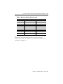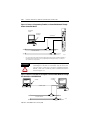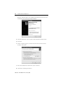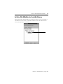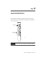
1
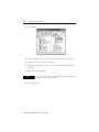
ControlNet
Universal PCI
Communication
Interface Card
1784-PCIC, 1784-PCICS
Series B
Installation
Instructions
Important User Information
Solid state equipment has operational characteristics differing from those of electromechanical equipment.
Safety Guidelines for the Application, Installation and Maintenance of Solid State Controls (Publication
SGI-1.1, available from your local Rockwell Automation sales office or online at
http://www.literature.rockwellautomation.com) describes some important differences between solid state
equipment and hard-wired electromechanical devices. Because of this difference, and also because of the
wide variety of uses for solid state equipment, all persons responsible for applying this equipment must
satisfy themselves that each intended application of this equipment is acceptable.
In no event will Rockwell Automation, Inc. be responsible or liable for indirect or consequential damages
resulting from the use or application of this equipment.
The examples and diagrams in this manual are included solely for illustrative purposes. Because of the many
variables and requirements associated with any particular installation, Rockwell Automation, Inc. cannot
assume responsibility or liability for actual use based on the examples and diagrams.
No patent liability is assumed by Rockwell Automation, Inc. with respect to use of information, circuits,
equipment, or software described in this manual.
Reproduction of the contents of this manual, in whole or in part, without written permission of Rockwell
Automation, Inc. is prohibited.
Throughout this manual we use notes to make you aware of safety considerations.
WARNING
Identifies information about practices or circumstances that can cause an explosion in a
hazardous environment, which may lead to personal injury or death, property damage,
or economic loss.
IMPORTANT
Identifies information that is critical for successful application and understanding of the
product.
ATTENTION
Identifies information about practices or circumstances that can lead to personal injury
or death, property damage, or economic loss. Attentions help you:
• identify a hazard
• avoid a hazard
• recognize the consequence
SHOCK HAZARD
BURN HAZARD
Labels may be located on or inside the drive to alert people that dangerous voltage may
be present.
Labels may be located on or inside the drive to alert people that surfaces may be
dangerous temperatures.
Table of Contents
Chapter 1
Install the 1784-PCIC or 1784-PCICS Communication Interface
Card
European Hazardous Location Approval (1784-PCIC only) .
European Zone 2 Certification. . . . . . . . . . . . . . . . . . .
North American Hazardous Location Approval . . . . . . . . .
Access the Computer’s PCI Local Bus Expansion Slots . . . .
Insert the Card Into the Computer. . . . . . . . . . . . . . . . . . .
Connect to the Network . . . . . . . . . . . . . . . . . . . . . . . . . .
Connect the Card Directly to the ControlNet Network . . . .
Connect to a Device on the ControlNet Network . . . . . . . .
.
.
.
.
.
.
.
.
.
.
.
.
.
.
.
.
.
.
.
.
.
.
.
.
. 1-3
. 1-3
. 1-4
. 1-5
. 1-6
. 1-7
. 1-9
1-10
Chapter 2
Install the Driver in Windows XP
Install the Driver in Windows XP for the First Time . . . . . . . . . 2-1
Update the Existing Driver in Windows XP . . . . . . . . . . . . . . . . 2-3
Chapter 3
Install the Driver in Windows 2000
Install the Driver in Windows 2000 for the First Time. . . . . . . . . 3-1
Update the Existing Driver in Windows 2000. . . . . . . . . . . . . . . 3-4
Chapter 4
Install the Driver in Windows 98/Me
Install the Driver in Windows 98/Me for the First Time . . . . . . . 4-1
Install the Virtual Backplane Driver . . . . . . . . . . . . . . . . . . . . . . 4-3
Update the Existing Driver in Windows 98/Me . . . . . . . . . . . . . 4-5
Publication 1784-IN003D-EN-P - January 2006
ii
Table of Contents
Chapter 5
Once You Have Completed the Installation
Register the EDS File . . . . . . . . . . . . . . . . . . . . . . . . . . . .
Configure the ControlNet Communications Driver
in RSLinx Software . . . . . . . . . . . . . . . . . . . . . . . . . . . . . .
Connect a SoftLogix Controller to the ControlNet Network .
Go Online With RSNetWorx for ControlNet Software . . . . .
Chapter 6
Interpret the LED Indicators
Chapter 7
Specifications
Index
Publication 1784-IN003D-EN-P - January 2006
. . . . 5-1
. . . . 5-2
. . . . 5-4
. . . . 5-7
Chapter
1
Install the 1784-PCIC or 1784-PCICS
Communication Interface Card
For Information On This Topic
See Page
Access the Computer’s PCI Local Bus Expansion Slots
1-5
Insert the Card Into the Computer
1-6
Connect to the Network
1-7
Connect the Card Directly to the ControlNet Network
1-9
Connect to a Device on the ControlNet Network
1-10
Before you install the card, be certain that you:
• know how to install hardware in your computer.
• consult your computer’s documentation for hardware installation
instructions.
TIP
Installation instructions for both the 1784-PCIC and 1784-PCICS
cards are exactly the same. In most illustrations, the 1784-PCIC
card is shown.
Refer to the following publications for more information:
• ControlNet Coax Media Planning and Installation, publication CNET-IN002
• ControlNet Communication Modules in Logix5000 Control Systems,
publication CNET-UM001
• SoftLogix5800 System User Manual, publication 1789-UM002
Publication 1784-IN003D-EN-P - January 2006
1-2
Install the 1784-PCIC or 1784-PCICS Communication Interface Card
ATTENTION
This equipment is intended for use in a Pollution Degree 2
industrial environment, in overvoltage Category II applications (as
defined in IEC publication 60664-1), at altitudes up to 2000 meters
without derating.
This equipment is considered Group 1, Class A industrial
equipment according to IEC/CISPR Publication 11. Without
appropriate precautions, there may be potential difficulties
ensuring electromagnetic compatibility in other environments due
to conducted as well as radiated disturbance.
This equipment is supplied as open type equipment. It must be
mounted within an enclosure that is suitably designed for those
specific environmental conditions that will be present and
appropriately designed to prevent personal injury resulting from
accessibility to live parts. The interior of the enclosure must be
accessible only by the use of a tool. Subsequent sections of this
publication may contain additional information regarding specific
enclosure type ratings that are required to comply with certain
product safety certifications.
NOTE: See NEMA Standards publication 250 and IEC publication
60529, as applicable, for explanations of the degrees of protection
provided by different types of enclosure. Also, see the appropriate
sections in this publication, as well as the Industrial Automation
Wiring and Grounding Guidelines, Allen-Bradley publication
1770-4.1, for additional installation requirements pertaining to this
equipment.
ATTENTION
Prevent Electrostatic Discharge
This equipment is sensitive to electrostatic discharge, which can
cause internal damage and affect normal operation. Follow these
guidelines when you handle this equipment:
•
•
•
•
•
•
Touch a grounded object to discharge potential static
Wear an approved grounding wriststrap
Do not touch connectors or pins on component boards
Do not touch circuit components inside the equipment
Use a static-safe workstation, if available
Store the equipment in appropriate static-safe packaging
when not in use.
Publication 1784-IN003D-EN-P - January 2006
Install the 1784-PCIC or 1784-PCICS Communication Interface Card
1-3
European Hazardous Location Approval (1784-PCIC only)
European Zone 2 Certification
The following applies when the product bears the EEx Marking:
This equipment is intended for use in potentially explosive atmospheres as defined
by European Union Directive 94/9/EC.
The LCIE (Laboratoire Central des Industries Electriques) certifies that this
equipment has been found to comply with the Essential Health and Safety
Requirements relating to the design and construction of Category 3 equipment
intended for use in potentially explosive atmospheres, given in Annex II to this
Directive. The examination and test results are recorded in confidential report No.
28 682 010.
Compliance with the Essential Health and Safety Requirements has been assured by
compliance with EN 50021.
IMPORTANT
This equipment is not resistant to sunlight or other sources of UV
radiation.
The secondary of a current transformer shall not be open-circuited
when applied in Class I, Zone 2 environments.
Equipment of lesser Enclosure Type Rating must be installed in an
enclosure providing at least IP54 protection when applied in Class
I, Zone 2 environments.
This equipment shall be used within its specified ratings defined
by Allen-Bradley.
Provision shall be made to prevent the rated voltage from being
exceeded by transient disturbances of more than 40% when
applied in Class I, Zone 2 environments.
Publication 1784-IN003D-EN-P - January 2006
1-4
Install the 1784-PCIC or 1784-PCICS Communication Interface Card
North American Hazardous Location Approval
The following information applies when
operating this equipment in hazardous
locations:
Informations sur l’utilisation de cet équipement en
environnements dangereux:
Products marked CL I, DIV 2, GP A, B, C, D are suitable
for use in Class I Division 2 Groups A, B, C, D,
Hazardous Locations and nonhazardous locations only.
Each product is supplied with markings on the rating
nameplate indicating the hazardous location
temperature code. When combining products within a
system, the most adverse temperature code (lowest T
number) may be used to help determine the overall
temperature code of the system. Combinations of
equipment in your system are subject to investigation
by the local Authority Having Jurisdiction at the time
of installation.
Les produits marqués CL I, DIV 2, GP A, B, C, D ne
conviennent qu’à une utilisation en environnements de
Classe I Division 2 Groupes A, B, C, D dangereux et non
dangereux. Chaque produit est livré avec des marquages
sur sa plaque d’identification qui indiquent le code de
température pour les environnements dangereux.
Lorsque plusieurs produits sont combinés dans un
système, le code de température le plus défavorable
(code de température le plus faible) peut être utilisé pour
déterminer le code de température global du système.
Les combinaisons d’équipements dans le système sont
sujettes à inspection par les autorités locales qualifiées
au moment de l’installation.
WARNING
EXPLOSION HAZARD
• Do not disconnect equipment
unless power has been
removed or the area is known
to be nonhazardous.
• Do not disconnect
connections to this
equipment unless power has
been removed or the area is
known to be nonhazardous.
Secure any external
connections that mate to this
equipment by using screws,
sliding latches, threaded
connectors, or other means
provided with this product.
• Substitution of components
may impair suitability for
Class I, Division 2.
• If this product contains
batteries, they must be
changed only in an area
known to be nonhazardous.
Publication 1784-IN003D-EN-P - January 2006
AVERTISSEMENT
RISQUE D’EXPLOSION
• Couper le courant ou
s’assurer que
l’environnement est
classé non dangereux
avant de débrancher
l'équipement.
• Couper le courant ou
s'assurer que
l’environnement est
classé non dangereux
avant de débrancher les
connecteurs. Fixer tous
les connecteurs externes
reliés à cet équipement à
l'aide de vis, loquets
coulissants, connecteurs
filetés ou autres moyens
fournis avec ce produit.
• La substitution de
composants peut rendre
cet équipement inadapté
à une utilisation en
environnement de Classe
I, Division 2.
• S’assurer que
l’environnement est
classé non dangereux
avant de changer les
piles.
Install the 1784-PCIC or 1784-PCICS Communication Interface Card
1-5
To install the card, you need to:
• access the computer’s expansion slots.
• insert the card into the computer.
IMPORTANT
The card’s dimensions are shown below.
6.5 in.
16.5 cm
4.2 in.
10.7 cm
31474-M
Access the Computer’s PCI Local Bus Expansion Slots
To install the card, you must access the computer’s PCI local bus expansion slots.
Follow these general steps, or refer to your computer’s user guide for further
instructions.
1. Shut down the host computer.
2. Remove the computer’s cover.
3. Select a vacant PCI local bus expansion slot.
4. Loosen the screw (if present) on the back (rear bracket) of the computer.
5. Remove the slot’s expansion cover.
Publication 1784-IN003D-EN-P - January 2006
1-6
Install the 1784-PCIC or 1784-PCICS Communication Interface Card
Insert the Card Into the Computer
WARNING
When used in a Class I, Division 2, hazardous location,
this equipment must be mounted in a suitable enclosure
with proper wiring method that complies with the
governing electrical codes.
If you insert or remove the card while host power is on,
an electrical arc can occur. This could cause an
explosion in hazardous location installations.
Be sure that power is removed or the area is
nonhazardous before proceeding.
1. Handle the card so that you prevent electrostatic discharge.
Refer to the Preface of this manual for more information.
2. Insert the card into the edge connector and tighten the expansion slot screw
(if present).
3. Replace the computer cover.
4. Turn on the computer to be certain that it comes up correctly.
If the Computer
Then
Turns on
Go to to the next section, Connect to the Network
Hangs up
Either the card is not seated correctly in the PCI slot or you have a
memory or I/O conflict. You should:
• remove and reinsert the card into the same PCI slot and
try again
• remove and reinsert the card into a different PCI slot and
try again
• remove all other non-essential cards and try again
If you continue to experience difficulty, contact your local
Rockwell Automation sales representative or distributor, or call
Rockwell Automation Technical Support at 440.646.5800.
Publication 1784-IN003D-EN-P - January 2006
Install the 1784-PCIC or 1784-PCICS Communication Interface Card
1-7
Connect to the Network
WARNING
When used in a Class I, Division 2, hazardous location, this
equipment must be mounted in a suitable enclosure with
proper wiring method that complies with the governing
electrical codes.
If you connect or disconnect the ControlNet cable with power
applied to this module or any device on the network, an
electrical arc can occur. This could cause an explosion in
hazardous location installations.
Be sure that power is removed or the area is nonhazardous
before proceeding.
After you have installed the card, you can connect it:
• directly to a ControlNet network, which requires a tap (page 1-9).
• to a device already connected to the ControlNet network (page 1-10).
See Figure 1.1 on page 1-8 for the connectors and indicators.
Publication 1784-IN003D-EN-P - January 2006
1-8
Install the 1784-PCIC or 1784-PCICS Communication Interface Card
Figure 1.1 1784-PCIC or 1784-PCICS Card (1784-PCIC Card Shown)
Diagnostic Status
Indicators
Network Access Port (NAP)
RJ-45 connector for connecting
programming terminals to devices on
a ControlNet network
!
Channel A
BNC connectors for connecting directly to
ControlNet network
Redundant Media
BNC Connectors
!
A
Channel B
!
B
!
Do not connect more than one
ControlNet network to this card.
Allen-Bradley
1784-PCIC
ControlNet
42281
ATTENTION
Do not connect different ControlNet networks to this card. If
you attempt to connect a second network to this card, your
communication system will operate erratically.
Publication 1784-IN003D-EN-P - January 2006
Install the 1784-PCIC or 1784-PCICS Communication Interface Card
1-9
Connect the Card Directly to the ControlNet Network
To connect the card directly to a ControlNet network, follow the instructions in
these publications:
• ControlNet Coax Tap Installation Instructions, publication 1786-IN007
• ControlNet Coax Media Planning and Installation Manual, publication
CNET-IN002
Figure 1.2 Connect the Card Directly to the ControlNet Network
1784-PCIC or
1784-PCICS
Desktop Host
Computer
1786-TPR, -TPS, -TPYR, or -TPYS Tap
ControlNet Network
42200
ATTENTION
If you connect the product to a cable system that does not
support redundant media, connect the tap dropline to the BNC
connector labeled channel A. Channel B is left unconnected.
If the cable system is redundant, connect the product so that
all devices on the network use the same cable for the same
channel. That is, all channel A connectors connect to one
cable; all channel B connectors connect to the other cable.
TIP
If you use a non-redundant cable system, all ControlNet
devices must be on the same channel, channel A.
Publication 1784-IN003D-EN-P - January 2006
1-10
Install the 1784-PCIC or 1784-PCICS Communication Interface Card
Connect to a Device on the ControlNet Network
The 1786-CP cable (Figure 1.3) connects a host computer to another ControlNet
device. It has two RJ-45 8-pin connectors.
Figure 1.3 1786-CP cable
RJ-45 8-pin Connectors
Connector 2
Connector 1
1786-CP Cable
30124-m
ATTENTION
Use only the 1786-CP cable when you connect a
programming terminal to the network through the Network
Acces Port (NAP). If you use a different cable, it could
result in possible network failures or product damage.
See Tables 1.1 and 1.2 for the wiring for the 1786-CP cable.
Table 1.1 Wiring For 1786-CP Cable (Connector 1)
Connector 1
Wire Number
Signal Mnemonic
Signal Name
1
ISO-GND
Isolated Ground
2
N.C.
No Connection
3
PTTX-H
Transmit Data High
4
PTTX-L
Transmit Data Low
5
PTRX-L
Receive Data Low
6
PTRX-H
Receive Data High
7
N.C.
No Connection
8
ISO-GND
Isolated Ground
Publication 1784-IN003D-EN-P - January 2006
Install the 1784-PCIC or 1784-PCICS Communication Interface Card
1-11
Table 1.2 Wiring For 1786-CP Cable (Connector 2)
Connector 2
Wire Number
Signal Mnemonic
Signal Name
1
ISO-GND
Isolated Ground
2
N.C.
No Connection
3
PTRX-H
Receive Data High
4
PTRX-L
Receive Data Low
5
PTTX-L
Transmit Data Low
6
PTTX-H
Transmit Data High
7
N.C.
No Connection
8
ISO-GND
Isolated Ground
When you use the RJ-45 connector, you can connect the card to a ControlNet
network without a tap through the Network Access Port (or NAP) of a
programmable controller, I/O adapter, or other ControlNet compliant devices.
See Figure 1.4 and Figure 1.5.
Publication 1784-IN003D-EN-P - January 2006
1-12
Install the 1784-PCIC or 1784-PCICS Communication Interface Card
Figure 1.4 Connect a Programming Terminal to a ControlNet Network Through
Another ControlNet Device
Programming
Terminal
1784-PCIC or
1784-PCICS
1786-CP Cable1
ControlNet
Product
ControlNet Network
42199
1
The 1786-CP cable can be plugged into any ControlNet product’s NAP to provide programming capability on
the ControlNet network. When you connect a programming terminal through this cable, it is counted as a
node and must have a unique address.
ATTENTION
If a SoftLogix5800 processor is running on the computer
containing the 1784-PCIC or 1784-PCICS card, do not use the
1786-CP cable to connect the card to the ControlNet network.
Instead, connect the card directly to the ControlNet network as
shown in Figure 1.2.
Figure 1.5 Connect a Portable Host Computer to the ControlNet Network Through
the 1784-PCIC or 1784-PCICS Card
Portable Host
Computer
1784-PCIC or
1784-PCICS
1784-PCC
Desktop Host
Computer
1784-PCC1 Cable
ControlNet Network
42198
Publication 1784-IN003D-EN-P - January 2006
Chapter
2
Install the Driver in Windows XP
For Information On This Topic
See Page
Install the Driver in Windows XP for the First Time
2-1
Update the Existing Driver in Windows XP
2-3
Install the Driver in Windows XP for the First Time
Follow these steps to install the driver for the first time on a personal computer
running Windows XP.
1. Shut down the computer.
2. Insert the 1784-PCIC or 1784-PCICS card into an unused PCI slot.
Refer to Chapter 1 for installation information.
3. Restart the computer.
Publication 1784-IN003D-EN-P - January 2006
2-2
Install the Driver in Windows XP
After the computer restarts, the operating system detects the new PCI card
and displays the Found New Hardware Wizard.
4. Select the Install from a list or specific location (Advanced) radio button.
5. Click Next.
6. On the screen that appears, click the Search for the best driver in these
locations radio button.
7. Check the Include this location in the search checkbox.
8. Uncheck the remaining checkboxes.
Publication 1784-IN003D-EN-P - January 2006
Install the Driver in Windows XP
2-3
9. Click Browse.
10. Navigate to the folder that contains the installation files.
The installation files can be found in the \Drivers\Win2K_WinXP folder on
the 1784-PCIC(S) Driver CD-ROM.
11. Click OK.
12. Click Next.
IMPORTANT
If prompted to overwrite existing files, click Yes.
13. Click Finish.
The driver is now ready to use. Go on to Chapter 5.
Update the Existing Driver in Windows XP
Follow these steps to update the existing device driver on a personal computer
running Windows XP.
IMPORTANT
During the update procedure, communication through the card will be
disrupted.
1. If you are browsing with RSLinx software, close RSWho.
2. Right-click My Computer.
Publication 1784-IN003D-EN-P - January 2006
2-4
Install the Driver in Windows XP
3. Click Manage.
4. In the left window pane, click the + to the left of System Tools to open it.
5. Under System Tools, click Device Manager.
6. In the right window pane, click the + to the left of A-B Virtual Backplane to
expand it.
7. Right-click A-B 1784-PCIC(S).
TIP
If you see more than one A-B 1784-PCIC(S) entry, perform the
update on only one of the entries.
8. Click Update Driver.
Publication 1784-IN003D-EN-P - January 2006
Install the Driver in Windows XP
2-5
The Hardware Update Wizard appears.
9. Select the Install from a list or specific location (Advanced) radio button.
10. Click Next.
11. On the screen that appears, click the Don’t search. I will choose the best
driver to install radio button.
12. Click Next.
13. Click Have Disk.
14. Click Browse.
Publication 1784-IN003D-EN-P - January 2006
2-6
Install the Driver in Windows XP
15. Navigate to the folder that contains the installation files.
The installation files can be found in the \Drivers\Win2K_WinXP folder on
the 1784-PCIC(S) Driver CD-ROM.
16. Click Open.
17. Click OK.
18. Select A-B 1784-PCIC(S) to highlight it.
19. Click Next.
IMPORTANT
If prompted to overwrite existing files, click Yes.
20. Click Finish.
21. Close the Device Manager screen.
22. Shut down and restart the computer.
The driver is now ready to use. Go on to Chapter 5.
Publication 1784-IN003D-EN-P - January 2006
Chapter
3
Install the Driver in Windows 2000
For Information On This Topic
See Page
Install the Driver in Windows 2000 for the First Time
3-1
Update the Existing Driver in Windows 2000
3-4
Install the Driver in Windows 2000 for the First Time
Follow these steps to install the driver for the first time on a personal computer
running Windows 2000.
1. Shut down the computer.
2. Insert the 1784-PCIC or 1784-PCICS card into an unused PCI slot.
Refer to Chapter 1 for installation information.
3. Restart the computer.
After the computer restarts, the operating system detects the new PCI card
and displays the Found New Hardware Wizard.
Publication 1784-IN003D-EN-P - January 2006
3-2
Install the Driver in Windows 2000
4. Click Next.
5. Click the Search for a suitable driver for my device (recommended) radio
button.
6. Click Next.
.
7. Check the Specify a location checkbox and uncheck the remaining
checkboxes.
Publication 1784-IN003D-EN-P - January 2006
Install the Driver in Windows 2000
3-3
8. Click Next.
9. Click Browse and navigate to the folder that contains the installation files.
The installation files can be found in the \Drivers\Win2K_WinXP folder on
the 1784-PCIC(S) Driver CD-ROM.
10. Click Open.
11. Click OK.
12. Click Next to install the new driver.
IMPORTANT
If prompted to overwrite existing files, click Yes.
13. Click Finish to close the Found New Hardware Wizard.
The driver is now ready to use. Go on to Chapter 5.
Publication 1784-IN003D-EN-P - January 2006
3-4
Install the Driver in Windows 2000
Update the Existing Driver in Windows 2000
Follow these steps to update the existing device driver on a personal computer
running Windows 2000.
IMPORTANT
During the update procedure, communication through the card
will be disrupted.
1. If you are browsing with RSLinx software, close RSWho.
2. Right-click My Computer.
3. Click Manage.
4. In the left window pane, click the + to the left of System Tools to open it.
5. Under System Tools, click Device Manager.
6. In the right window pane, click the + to the left of A-B Virtual Backplane to
expand it.
7. Right-click A-B 1784-PCIC(S).
TIP
If you see more than one A-B 1784-PCIC(S) entry, perform the
update on only one of the entries.
8. Click Properties.
Publication 1784-IN003D-EN-P - January 2006
Install the Driver in Windows 2000
3-5
9. Click the Driver tab.
10. Click Update Driver.
The Upgrade Device Driver Wizard appears.
11. Click Next.
12. Click the Display a list of the known drivers for this device so I can choose a
specific driver radio button
Publication 1784-IN003D-EN-P - January 2006
3-6
Install the Driver in Windows 2000
13. Click Next.
14. Click Have Disk.
15. Click Browse.
16. Navigate to the folder that contains the installation files.
The installation files can be found in the \Drivers\Win2K_WinXP folder on
the 1784-PCIC(S) Driver CD-ROM.
17. Click Open.
18. Click OK.
19. Select A-B 1784-PCIC(S) to highlight it.
Publication 1784-IN003D-EN-P - January 2006
Install the Driver in Windows 2000
3-7
20. Click Next.
21. Click Next to install the new driver.
IMPORTANT
If prompted to overwrite existing files, click Yes.
22. Click Finish.
23. Close the A-B 1784-PCIC(S) Properties screen.
24. Close the Device Manager screen.
25. Shut down and restart the computer.
The driver is now ready to use. Go on to Chapter 5.
Publication 1784-IN003D-EN-P - January 2006
3-8
Install the Driver in Windows 2000
Notes:
Publication 1784-IN003D-EN-P - January 2006
Chapter
4
Install the Driver in Windows 98/Me
For Information On This Topic
See Page
Install the Driver in Windows 98/Me for the First Time
4-1
Install the Virtual Backplane Driver
4-3
Update the Existing Driver in Windows 98/Me
4-5
Install the Driver in Windows 98/Me for the First Time
Follow these steps to install the driver for the first time on a personal computer
running Windows 98/Me.
1. Shut down the computer.
2. Insert the 1784-PCIC or 1784-PCICS card into an unused PCI slot.
Refer to Chapter 1 for installation information.
3. Restart the computer.
After the computer restarts, the operating system detects the new PCI card
and displays the Add New Hardware wizard.
Publication 1784-IN003D-EN-P - January 2006
4-2
Install the Driver in Windows 98/Me
4. Click Next.
5.
Click the Search for the best driver for your device (Recommended) radio
button.
6. Click Next.
7. Check the Specify a location checkbox and uncheck the remaining
checkboxes.
8. Click Browse and navigate to the folder that contains the installation files.
The installation files can be found in the \Drivers\Win98 folder on the
1784-PCIC(S) Driver CD-ROM.
Publication 1784-IN003D-EN-P - January 2006
Install the Driver in Windows 98/Me
4-3
9. Click OK.
10. Click Next.
11. Click Next.
IMPORTANT
If prompted to overwrite existing files, click Yes.
12. Click Finish.
Install the Virtual Backplane Driver
So that the 1784-PCICS drivers work properly after you install them for the first
time, you must install the Virtual Backplane Driver. Follow this procedure to install
the Virtual Backplane Driver.
1. Select Start ⇒Settings ⇒Control Panel.
2. Double-click Add New Hardware.
You see the Add New Hardware Wizard.
3. Click Next.
Windows searches for the new Plug and Play devices.
4. Click Next.
Publication 1784-IN003D-EN-P - January 2006
4-4
Install the Driver in Windows 98/Me
5. Click the No, I want to select the hardware from a list radio button.
6. Click Next.
7. Select A-B Virtual Backplane from the list of hardware types.
8. Click Next.
9. Select A-B Virtual Backplane from the list of models.
10. Click Next.
11. Click Finish.
The driver is now ready to use. Go on to Chapter 5.
Publication 1784-IN003D-EN-P - January 2006
Install the Driver in Windows 98/Me
4-5
Update the Existing Driver in Windows 98/Me
Follow these steps to update the existing device driver on a personal computer
running Windows 98/Me.
IMPORTANT
During the update procedure, communication through the card
will be disrupted.
1. If you are browsing with RSLinx software, close RSWho.
2. Right-click My Computer.
3. Click on the Device Manager tab.
4. In the left window pane, click the + to the left of A-B Virtual Backplane to
expand it.
5. Right-click on A-B 1784-PCIC(S).
TIP
If you see more than one A-B 1784-PCIC(S) entry, perform the
update on only one of the entries.
6. Click Properties.
Publication 1784-IN003D-EN-P - January 2006
4-6
Install the Driver in Windows 98/Me
7. Click the Driver tab.
8. Click Update Driver.
9. Click Next.
10. Click the Display a list of all the drivers in a specific location so you can
select the driver you want radio button.
Publication 1784-IN003D-EN-P - January 2006
Install the Driver in Windows 98/Me
4-7
11. Click Next.
12. Click Have Disk.
13. Click Browse, then navigate to the folder that contains the installation files.
The installation files can be found in the \Drivers\Win98 folder on the
1784-PCIC(S) Driver CD-ROM.
14. Click OK.
15. Click OK.
16. Select A-B 1784-PCIC(S) to highlight it.
17. Click Next.
18. Click Next.
19. Click Next.
IMPORTANT
If prompted to overwrite existing files, click Yes.
20. Click Finish.
Publication 1784-IN003D-EN-P - January 2006
4-8
Install the Driver in Windows 98/Me
21. Close the A-B 1784-PCIC(S) Properties screen.
22. Close the System Properties screen.
23. Shut down and restart the computer.
The driver is now ready to use. Go on to Chapter 5.
Publication 1784-IN003D-EN-P - January 2006
Chapter
5
Once You Have Completed the Installation
Once you have installed the drivers, you can do the following:
For Information On This Topic
See Page
Register the EDS File
5-1
Configure the ControlNet Communications Driver in RSLinx Software
5-2
Connect a SoftLogix Controller to the ControlNet Network
5-4
Go Online With RSNetWorx for ControlNet Software
5-7
Register the EDS File
The EDS files can be found in the \EDS Files folder on the 1784-PCIC(S) Driver CD-ROM
or they can be downloaded from http://www.ab.com/networks/eds/.
Use the EDS wizard in either RSLinx or RSNetWorx for ControlNet software to register
these EDS files for the 1784-PCIC or 1784-PCICS card:
Catalog Number
EDS File
1784-PCIC
0001000C00490400.eds
1784-PCICS
0001000C003F0400.eds
• In Windows, select Start ⇒Programs ⇒Rockwell Software ⇒RSLinx Tools
⇒EDS Hardware Installation Tool.
• In RSNetWorx for ControlNet software, select Tools ⇒EDS Wizard.
Publication 1784-IN003D-EN-P - January 2006
5-2
Once You Have Completed the Installation
Configure the ControlNet Communications Driver in RSLinx
Software
Follow this procedure to configure the ControlNet communication driver.
IMPORTANT
Do not use these steps to configure a ControlNet
communication driver for any application that uses a
SoftLogix5800 controller. For information on configuring the
ControlNet card for use with SoftLogix5800 controllers, refer
to page 5-4.
1. Install RSLinx software, version 2.42.00 or later, on your computer.
2. In RSLinx software, select Configure Drivers.
A. Click Communications.
B. Click Configure Drivers.
3. Select a driver for ControlNet devices.
Publication 1784-IN003D-EN-P - January 2006
Once You Have Completed the Installation
5-3
In the example below, we chose the 1784-PCICS card.
A. Use the pull-down menu to
select the ControlNet driver.
B. Click Add New.
4. Name the new ControlNet driver.
A. Name the driver.
This example shows the default
name (AB_PCIC-1) that RSLinx
software uses.
B. Click OK.
Publication 1784-IN003D-EN-P - January 2006
5-4
Once You Have Completed the Installation
5. After you create the driver, configure it to correspond to the ControlNet
module within your computer.
A. If multiple cards are located
in your computer, choose the
correct one.
B. Make sure you use the
correct Network Address.
C. Click OK.
The driver is now available in RSLinx software. You can browse the network by
expanding ControlNet port on the desired 1784-PCIC or 1784-PCICS communication
card.
Connect a SoftLogix Controller to the ControlNet Network
The SoftLogix5800 controller is a soft control solution that runs in a Microsoft
Windows 2000 or Windows XP environment. When using this controller, you must
install the SoftLogix5800 Chassis monitor, a virtual chassis that takes the place of
hardware chassis used with other Logix5000 controllers.
Before you can connect the SoftLogix system to the ControlNet network, you must
create the 1784-PCIC or 1784-PCICS card as part of the SoftLogix chassis.
1. In the SoftLogix chassis monitor, create a New Module.
A. Click Slot.
B. Click Create Module.
Publication 1784-IN003D-EN-P - January 2006
Once You Have Completed the Installation
5-5
2. Select the 1784-PCIC or 1784-PCICS card.
A. Select the ControlNet card.
B. Specify the virtual
backplane slot number.
C. Click OK.
3. Select the serial number of the 1784-PCIC or 1784-PCICS card you want.
If you previously configured the card that you selected by serial number, the
chassis monitor remembers the configuration from the last time you used the
card (whether in the same or different slot).
A. If multiple cards are located in your
computer, choose the serial number of
the correct one.
B. Click Next.
4. Configure the card.
A. Specify the node address on the
ControlNet network.
B. Enter the label name for the card
(this is the name you wrote on the
label of the card to help you identify
the card from others in the same
computer).
C. Click Finish.
Publication 1784-IN003D-EN-P - January 2006
5-6
Once You Have Completed the Installation
You can specify any slot number greater than 0 for the communication card. RSLinx
software resides in slot 0.
By creating the card in the virtual chassis, you configure the communication driver
information needed by the SoftLogix controller. Do not use RSLinx software to
install the ControlNet communication driver to the same card; installation through
RSLinx software adds the potential for conflicting configuration between RSLinx
software and the SoftLogix chassis monitor.
Instead, configure a Virtual Backplane driver in RSLinx software:
5. Select Communications ⇒Configure Drivers...
6. Under Available Driver Types, select Virtual Backplane (SoftLogix 58xx).
7. Click Add New.
8. Enter a name for the driver.
9. Click OK.
10. Click on Close.
The Virtual Backplane driver is now ready to use.
After you add the card to the chassis monitor and configure a Virtual Backplane
driver, you can browse the network by expanding the Virtual Backplane driver and
then expanding the port on the desired 1784-PCIC or 1784-PCICS communication
card. Browsing the ControlNet network through the Virtual Backplane driver
provides the same functionality as the RSLinx driver.
Publication 1784-IN003D-EN-P - January 2006
Once You Have Completed the Installation
5-7
Go Online With RSNetWorx for ControlNet Software
When going online with RSNetWorx for ControlNet software via the 1784-PCIC or
1784-PCICS card, select Port A, ControlNet under the card in the Virtual Chassis.
Do not select AB-PCIC-1, ControlNet.
Publication 1784-IN003D-EN-P - January 2006
5-8
Once You Have Completed the Installation
Notes:
Publication 1784-IN003D-EN-P - January 2006
Chapter
6
Interpret the LED Indicators
The LED indicators on the card give you information about the card and the
network when you’re connected via the BNC connectors. Table 6.1 outlines the
states and explains what each state means to you and the action you should take, if
any, to correct that state.
Diagnostic Status
Indicators
!
Redundant Media
BNC Connectors
!
A
!
B
42281
IMPORTANT
When you connect the module to a ControlNet network using
only the Network Acces Port (NAP), the LEDs are meaningless.
Publication 1784-IN003D-EN-P - January 2006
6-2
Interpret the LED Indicators
• Steady - indicator is on continuously in the defined state.
• Alternating - the two indicators alternate between the two defined states at
the same time (applies to both indicators viewed together). The two
indicators are always in opposite states, out of phase.
• Flashing - the indicator alternates between the two defined states (applies to
each indicator viewed independent of the other). If both indicators flash,
they must flash together, in phase.
Table 6.1 ControlNet status interpretation
Cause
A and
Off
Action
B
• No power
• None or apply power to the personal
computer
• 1784-PCIC or
1784-PCICS driver
not started
• Start RSLinx software
• Faulted card
• Check operating system event log for details
of fault (if the personal computer’s operating
system supports an event log)
• Verify that the 1784-PCIC or 1784-PCICS
driver has been configured properly in RSLinx
software
• Cycle power to the computer
• Verify that you have firmly inserted the
1784-PCIC or 1784-PCICS card into a PCI local
bus expansion slot and that the expansion
slot screw is tightened
• If fault persists, contact your Rockwell
Automation representative or distributor
Publication 1784-IN003D-EN-P - January 2006
Interpret the LED Indicators
6-3
Table 6.1 ControlNet status interpretation
Cause
A and
Action
B
• Faulted card
Steady red
• Check operating system event log for details
of fault (if the personal computer’s operating
system supports an event log)
• Cycle power to the computer
• Verify that you have firmly inserted the
1784-PCIC or 1784-PCICS card into a PCI local
bus expansion slot and that the expansion
slot screw is tightened
• If fault persists, contact your Rockwell
Automation representative or distributor
Alternating red/green
Alternating red/off
• Self-test
• None
• Incorrect channel
configuration
• Verify that the ControlNet network is
connected to the correct channel of the
1784-PCIC or 1784-PCICS card (for example,
if the ControlNet network is configured for
channel A only, then the card must be
connected to the network via channel A)
• Incorrect node
configuration
• Check 1784-PCIC or 1784-PCICS node
address and other ControlNet configuration
parameters
• Duplicate
ControlNet node
address
Cause
A or
Action
B
Off
• Channel disabled
• Use RSNetWorx for ControlNet sofware to
configure the ControlNet network for
redundant media, if required
Steady green
• Normal operation
• None
Flashing green/off
• Temporary
network errors
• Check media for broken cables, loose
connectors, or missing terminators
• If condition persists, refer to the ControlNet
Media Planning and Installation Manual,
publication CNET-IN002
Flashing red/off
• Media fault
• Check media for broken cables, loose
connectors, or missing terminators
• If condition persists, refer to the ControlNet
Media Planning and Installation Manual,
publication CNET-IN002
Publication 1784-IN003D-EN-P - January 2006
6-4
Interpret the LED Indicators
Cause
A or
Action
B
Flashing red/off
• No other nodes
present on
network
• Add other nodes to the network
Flashing red/green
• Incorrect node
address
• Change 1784-PCIC or 1784-PCICS node
address so that it is less than or equal to
UMAX(1)
• Stop and restart the 1784-PCIC or
1784-PCICS driver in RSLinx software
• Incorrect network
configuration
• Use RSNetWorx for ControlNet software to
reconfigure the ControlNet network so that
UMAX(1) is greater than or equal to the
1784-PCIC or 1784-PCICS node address
(1)
UMAX is the highest node address on a ControlNet network that can transmit data.
Publication 1784-IN003D-EN-P - January 2006
Chapter
7
Specifications
PCI local bus
Compliant to PCI revision 2.2.
The 1784-PCIC and 1784-PCICS cards are compatible with 5V and 3.3V PCI
slots, 32-bit and 64-bit PCI slots, and PCI-X slots.
Attention: The 1784-PCIC and 1784-PCICS cards are not compatible with PCI
Express and should not be inserted into a PCI Express slot.
Mechanical form factor, H x L
Universal PCI 32-bit short card
10.7 cm (4.2 in.) x 16.5 cm (6.5 in.) L
Driver compatibility
Microsoft Windows XP with Service Pack 1 or higher
Microsoft Windows 2000 with Service Pack 4 or higher
Microsoft Windows 98
Microsoft Windows Me
Software compatibility
Rockwell Software RSLinx software, version 2.42.00 or later
Operational temperature
IEC 60068-2-1 (Test Ad, Operating Cold),
IEC 60068-2-2 (Test Bd, Operating Dry Heat),
IEC 60068-2-14 (Test Nb, Operating Thermal Shock):
0...55 ° C (32...131 ° F)
The operating parameters describe the environment within the PCI slot.
Refer to the documentation for your computer for environmental
requirements. This card should not exceed those specifications.
Storage temperature
IEC 60068-2-1 (Test Ab, Unpackaged Nonoperating Cold),
IEC 60068-2-2 (Test Bb, Unpackaged Nonoperating Dry Heat),
IEC 60068-2-14 (Test Na, Unpackaged Nonoperating Thermal Shock):
-40...85 ° C (-40...185 ° F)
Relative humidity
IEC 60068-2-30 (Test Db, Un-packaged Nonoperating Damp Heat):
5...95% noncondensing
Vibration
IEC 60068-2-6 (Test Fc, Operating):
2g @ 10...500Hz
Operating shock
IEC 60068-2-27 (Test Ea, Unpackaged Shock):
30 g
Non-operating shock
IEC 60068-2-27 (Test Ea, Unpackaged Shock):
50 g
Emissions
CISPR 11:
Group 1, Class A
ESD immunity
IEC 61000-4-2:
6 kV contact discharges
8 kV air discharges
Radiated RF immunity
IEC 61000-4-3:
10V/m with 1 k Hz sine-wave 80%AM from 80 MHz...2000 MHz
10V/m with 200 Hz 50% pulse 100%AM at 900 MHz
10V/m with 200 Hz 50% pulse 100%AM at 1890 MHz
Publication 1784-IN003D-EN-P - January 2006
7-2
Specifications
EFT/B immunity
IEC 61000-4-4:
± 2 kV at 5 kHz on communications ports
Surge transient immunity
IEC 61000-4-5:
± 2 kV line-earth (CM) on communications ports
Conducted RF immunity
IEC 61000-4-6:
10Vrms with 1 kH sine-wave 80% AM from 150kHz...80MHz
Enclosure type rating
None (open-style)
Power requirements
In US, this equipment must be powered from UL Listed Information
Technology Equipment or UL Listed Industrial Control Equipment. In Canada,
this equipment must be powered by an SELV source, CSA Certified
Information Technology Equipment, or CSA Certified Process Control
Equipment.
5V dc, 700 mA max., Class 2
Power dissipation
3.5 W
Isolation voltage (continuous-voltage
withstand rating)
50V continuous
Tested to withstand 600V for 60 s
2 - on communications ports
Wiring category(1)
Certifications (when product is marked)
(2)
UR UL Recognized Component Industrial Control Equipment
CSA CSA Accepted Component for Process Control Equipment
CSA Accepted Component for Process Control Equipment in Class
I, Division 2 Group A,B,C,D Hazardous Locations
CE European Union 89/336/EEC EMC Directive, compliant with:
EN 50082-2; Industrial Immunity
EN 61326; Meas./Control/Lab., Industrial Requirements
EN 61000-6-2; Industrial Immunity
EN 61000-6-4; Industrial Emissions
C-tick Australian Radiocommunications Act, compliant with:
AS/NZS CISPR 11; Industrial Emissions
EEx (1784-PCIC only) European Union 94/9/EC ATEX Directive,
compliant with:
EN 50021; Potentially Explosive Atmospheres, Protection “n”
(Zone 2)
CI ControlNet International conformance tested to ControlNet
specifications
(1)
Use this Conductor Category information for planning conductor routing. Refer to Industrial Automation Wiring and
Grounding Guidelines, publication 1770-4.1.
(2)
See the Product Certification link at www.ab.com for Declarations of Conformity, Certificates, and other certification details.
Publication 1784-IN003D-EN-P - January 2006
Index
C
card, install 1-1
configure ControlNet communications driver
in RSLinx 5-2, 5-7
connect
a SoftLogix controller to the ControlNet network 5-4
the card directly to the ControlNet network
1-9
to a device on the ControlNet network
ControlNet network
connect to 1-9
connect to a device on 1-10
1-10
install the driver
in Windows 2000 3-1
in Windows 98/Me 4-1
in Windows XP 2-1
install the Virtual Backplane Driver
4-3
L
LEDs
status indicator
6-1
R
RSLinx
configure ControlNet communications driver
D
5-2, 5-7
driver
install in Windows 2000 for the first time 3-1
install in Windows 98/Me 4-1
install in Windows 98/Me for the first time
4-1
install in Windows XP 2-1
install in Windows XP for the first time 2-1
update the existing driver in Windows 2000
3-4
update the existing driver in Windows 98/Me
4-5
update the existing driver in Windows XP
2-3
I
install the 1784-PCIC and 1784-PCICS
Communication Interface Cards
S
specifications 7-1
status indicator LEDs
6-1
U
update the existing driver
in Windows 2000 3-4
in Windows 98/Me 4-5
in Windows XP 2-3
V
1-1
Virtual Backplane Driver
install 4-3
Publication 1784-IN003D-EN-P - January 2006
2
Index
Notes:
Publication 1784-IN003D-EN-P - January 2006
How Are We Doing?
Your comments on our technical publications will help us serve you better in the future.
Thank you for taking the time to provide us feedback.
You can complete this form and mail (or fax) it back to us or email us at
[email protected]
Pub. Title/Type
ControlNet Universal PCI Communication Interface Card
Cat. No.
1784-PCIC,
1784-PCICS,
Series B
Pub. No.
1784-IN003D-EN-P Pub. Date
January 2006
Part No. 953002-33
Where applicable, please rank the feature (1=needs improvement, 2=satisfactory, 3=outstanding).
Overall Usefulness
1
2
3
How can we make this publication more useful for you?
Completeness
1
2
3
Can we add more information to help you?
(all necessary
information is provided)
Technical Accuracy
1
2
3
illustration
feature
example
guideline
other
explanation
definition
Can we be more accurate?
(all information is
correct)
Clarity
procedure/step
text
1
2
3
illustration
How can we make things clearer?
(all information is easy
to understand)
Other Comments
You can add additional comments on the back of this form.
Your Name
Location/Phone
Your Title/Function
Would you like us to contact you regarding your comments?
___No, there is no need to contact me
___Yes, please email me at __________________________
___Yes, please call me
___Yes, please contact me via ________________________
Return this form to:Rockwell Automation Technical Communications, 1 Allen-Bradley Dr., Mayfield Hts., OH 44124-9705
Fax: 440-646-3525 Email: [email protected]
Publication CIG-CO521C-EN-P – May 2003
PN 957782-91
PLEASE FASTEN HERE (DO NOT STAPLE)
Other Comments
PLEASE FOLD HERE
NO POSTAGE
NECESSARY
IF MAILED
IN THE
UNITED STATES
BUSINESS REPLY MAIL
FIRST-CLASS MAIL PERMIT NO. 18235 CLEVELAND OH
POSTAGE WILL BE PAID BY THE ADDRESSEE
1 ALLEN-BRADLEY DR
MAYFIELD HEIGHTS OH 44124-9705
1 ALLEN-BRADLEY DR
Rockwell Automation Support
Rockwell Automation provides technical information on the web to assist you in
using our products. At http://support.rockwellautomation.com, you can find
technical manuals, a knowledge base of FAQs, technical and application notes,
sample code and links to software service packs, and a MySupport feature that you
can customize to make the best use of these tools.
For an additional level of technical phone support for installation, configuration
and troubleshooting, we offer TechConnect Support programs. For more
information, contact your local distributor or Rockwell Automation representative,
or visit http://support.rockwellautomation.com.
Installation Assistance
If you experience a problem with a hardware module within the first 24 hours of
installation, please review the information that's contained in this manual. You can
also contact a special Customer Support number for initial help in getting your
module up and running:
United States
1.440.646.3223
Monday – Friday, 8am – 5pm EST
Outside United
States
Please contact your local Rockwell Automation representative for any
technical support issues.
New Product Satisfaction Return
Rockwell tests all of our products to ensure that they are fully operational when
shipped from the manufacturing facility. However, if your product is not
functioning and needs to be returned:
United States
Contact your distributor. You must provide a Customer Support case number
(see phone number above to obtain one) to your distributor in order to
complete the return process.
Outside United
States
Please contact your local Rockwell Automation representative for return
procedure.
Publication 1784-IN003D-EN-P - January 2006
Supersedes Publication 1784-IN003C-EN-P - October 2004
PN 953002-33
Copyright © 2006 Rockwell Automation, Inc. All rights reserved. Printed in USA