1
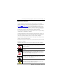
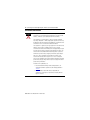
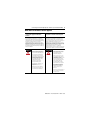
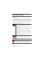
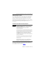
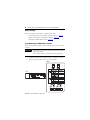
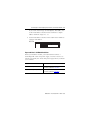
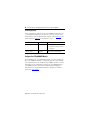
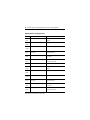
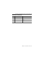
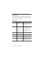
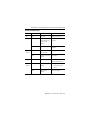
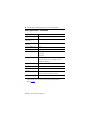
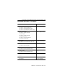
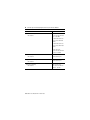
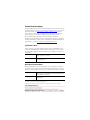
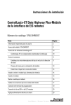
Installation Instructions
ControlLogix-XT Data Highway Plus-Remote
I/O Interface Module
Catalog Number 1756-DHRIOXT
Topic
Page
Important User Information
3
About the 1756-DHRIOXT Module
7
About ControlLogix-XT Systems
9
ControlLogix-XT with Traditional ControlLogix Components
Before You Begin
9
10
Set the Network Type and Node Address Switches
10
Prepare the Chassis for Module Installation
11
Determine Module Slot Location
12
Installing and Removing the Module Under Power
12
Install the Module
13
Remove or Replace the Module
14
Wire the Connectors for the Module Channels
15
Connect the Programming Terminal
16
Connect the DH+ or Remote I/O Network
17
Apply Chassis Power
17
Check Power Supply and Module Status
18
2 ControlLogix-XT Data Highway Plus-Remote I/O Interface Module
Topic
Page
Alphanumeric Display Startup Sequence
19
Power Supply Status
20
Alphanumeric Display Codes
21
Status Indicators
24
General Specifications - 1756-DHRIOXT
26
Environmental Specifications - 1756-DHRIOXT
27
Certifications - 1756-DHRIOXT
29
Additional Resources
30
Publication 1756-IN638A-EN-P - March 2009
ControlLogix-XT Data Highway Plus-Remote I/O Interface Module 3
Important User Information
Solid state equipment has operational characteristics differing from those of electromechanical
equipment. Safety Guidelines for the Application, Installation and Maintenance of Solid State Controls
(Publication SGI-1.1 available from your local Rockwell Automation sales office or online at
http://literature.rockwellautomation.com) describes some important differences between solid state
equipment and hard-wired electromechanical devices. Because of this difference, and also because of
the wide variety of uses for solid state equipment, all persons responsible for applying this equipment
must satisfy themselves that each intended application of this equipment is acceptable.
In no event will Rockwell Automation, Inc. be responsible or liable for indirect or consequential damages
resulting from the use or application of this equipment.
The examples and diagrams in this manual are included solely for illustrative purposes. Because of the
many variables and requirements associated with any particular installation, Rockwell Automation, Inc.
cannot assume responsibility or liability for actual use based on the examples and diagrams.
No patent liability is assumed by Rockwell Automation, Inc. with respect to use of information, circuits,
equipment, or software described in this manual.
Reproduction of the contents of this manual, in whole or in part, without written permission of Rockwell
Automation, Inc., is prohibited.
Throughout this manual, when necessary, we use notes to make you aware of safety considerations.
WARNING
IMPORTANT
ATTENTION
SHOCK HAZARD
BURN HAZARD
Identifies information about practices or circumstances that can cause an explosion
in a hazardous environment, which may lead to personal injury or death, property
damage, or economic loss.
Identifies information that is critical for successful application and understanding of
the product.
Identifies information about practices or circumstances that can lead to personal
injury or death, property damage, or economic loss. Attentions help you identify a
hazard, avoid a hazard and recognize the consequences.
Labels may be on or inside the equipment, for example, a drive or motor, to alert
people that dangerous voltage may be present.
Labels may be on or inside the equipment, for example, a drive or motor, to alert
people that surfaces may reach dangerous temperatures.
Publication 1756-IN638A-EN-P - March 2009
4 ControlLogix-XT Data Highway Plus-Remote I/O Interface Module
Environment and Enclosure
ATTENTION
This equipment is intended for use in a Pollution Degree 2 industrial
environment, in overvoltage Category II applications (as defined in IEC
60664-1), at altitudes up to 2000 m (6562 ft) without derating.
This equipment is considered Group 1, Class A industrial equipment
according to IEC/CISPR 11. Without appropriate precautions, there may
be difficulties with electromagnetic compatibility in residential and other
environments due to conducted and radiated disturbances.
This equipment is supplied as open-type equipment. It must be mounted
within an enclosure that is suitably designed for those specific
environmental conditions that will be present and appropriately designed
to prevent personal injury resulting from accessibility to live parts. The
enclosure must have suitable flame-retardant properties to prevent or
minimize the spread of flame, complying with a flame spread rating of
5VA, V2, V1, V0 (or equivalent) if non-metallic. The interior of the
enclosure must be accessible only by the use of a tool. Subsequent
sections of this publication may contain additional information regarding
specific enclosure type ratings that are required to comply with certain
product safety certifications.
In addition to this publication, see:
• Industrial Automation Wiring and Grounding Guidelines, for
additional installation requirements, Allen-Bradley publication
1770-4.1.
• NEMA Standards 250 and IEC 60529, as applicable, for
explanations of the degrees of protection provided by different
types of enclosure.
Publication 1756-IN638A-EN-P - March 2009
ControlLogix-XT Data Highway Plus-Remote I/O Interface Module 5
North American Hazardous Location Approval
The following information applies when
operating this equipment in hazardous
locations:
Informations sur l'utilisation de cet
équipement en environnements dangereux:
Products marked "CL I, DIV 2, GP A, B, C, D" are suitable for
use in Class I Division 2 Groups A, B, C, D, Hazardous
Locations and nonhazardous locations only. Each product is
supplied with markings on the rating nameplate indicating
the hazardous location temperature code. When
combining products within a system, the most adverse
temperature code (lowest "T" number) may be used to help
determine the overall temperature code of the system.
Combinations of equipment in your system are subject to
investigation by the local Authority Having Jurisdiction at
the time of installation.
Les produits marqués "CL I, DIV 2, GP A, B, C, D" ne
conviennent qu'à une utilisation en environnements de
Classe I Division 2 Groupes A, B, C, D dangereux et non
dangereux. Chaque produit est livré avec des marquages sur
sa plaque d'identification qui indiquent le code de
température pour les environnements dangereux. Lorsque
plusieurs produits sont combinés dans un système, le code de
température le plus défavorable (code de température le plus
faible) peut être utilisé pour déterminer le code de
température global du système. Les combinaisons
d'équipements dans le système sont sujettes à inspection par
les autorités locales qualifiées au moment de l'installation.
WARNING
EXPLOSION HAZARD • Do not disconnect equipment unless
power has been removed or the
area is known to be nonhazardous.
• Do not disconnect connections to
this equipment unless power has
been removed or the area is known
to be nonhazardous. Secure any
external connections that mate to
this equipment by using screws,
sliding latches, threaded
connectors, or other means
provided with this product.
• Substitution of components may
impair suitability for Class I,
Division 2.
• If this product contains batteries,
they must only be changed in an
area known to be nonhazardous.
AVERTISSEMENT
RISQUE D’EXPLOSION –
• Couper le courant ou s'assurer
que l'environnement est classé
non dangereux avant de
débrancher l'équipement.
• Couper le courant ou s'assurer
que l'environnement est classé
non dangereux avant de
débrancher les connecteurs. Fixer
tous les connecteurs externes
reliés à cet équipement à l'aide
de vis, loquets coulissants,
connecteurs filetés ou autres
moyens fournis avec ce produit.
• La substitution de composants
peut rendre cet équipement
inadapté à une utilisation en
environnement de Classe I,
Division 2.
• S'assurer que l'environnement est
classé non dangereux avant de
changer les piles.
Publication 1756-IN638A-EN-P - March 2009
6 ControlLogix-XT Data Highway Plus-Remote I/O Interface Module
European Hazardous Location Approval
European Zone 2 Certification (The following applies when the product bears the
Ex or EEx Marking)
This equipment is intended for use in potentially explosive atmospheres as defined by
European Union Directive 94/9/EC and has been found to comply with the Essential Health
and Safety Requirements relating to the design and construction of Category 3 equipment
intended for use in potentially explosive atmospheres, given in Annex II to this Directive.
Compliance with the Essential Health and Safety Requirements has been assured by
compliance with EN 60079-15 and EN 60079-0.
WARNING
•This equipment must be installed in an enclosure providing at least
IP54 protection when applied in Zone 2 environments.
•This equipment shall be used within its specified ratings defined by
Allen-Bradley.
•Provision shall be made to prevent the rated voltage from being
exceeded by transient disturbances of more than 40% when applied in
Zone 2 environments.
•This equipment must be used only with ATEX certified backplanes.
•Secure any external connections that mate to this equipment by using
screws, sliding latches, threaded connectors, or other means provided
with this product.
•Do not disconnect equipment unless power has been removed or the
area is known to be nonhazardous.
ATTENTION
ATTENTION
This equipment is not resistant to sunlight or other sources of UV
radiation.
Personnel responsible for the application of safety-related programmable
electronic systems (PES) shall be aware of the safety requirements in the
application of the system and shall be trained in using the system.
Publication 1756-IN638A-EN-P - March 2009
ControlLogix-XT Data Highway Plus-Remote I/O Interface Module 7
Preventing Electrostatic Discharge
ATTENTION
This equipment is sensitive to electrostatic discharge, which can cause
internal damage and affect normal operation. Follow these guidelines
when you handle this equipment:
•
•
•
•
•
•
Touch a grounded object to discharge potential static.
Wear an approved grounding wriststrap.
Do not touch connectors or pins on component boards.
Do not touch circuit components inside the equipment.
Use a static-safe workstation, if available.
Store the equipment in appropriate static-safe packaging
when not in use.
About the 1756-DHRIOXT Module
You can use the 1756-DHRIOXT module to communicate on a DH+
or remote I/O network.
The 1756-DHRIOXT module functions in the same way as the
traditional 1756-DHRIO module. For information about configuring
and using both the 1756-DHRIOXT and 1756-DHRIO module, see the
ControlLogix Data Highway Plus-Remote I/O Communication
Interface Module User Manual, publication 1756-UM514.
Publication 1756-IN638A-EN-P - March 2009
8 ControlLogix-XT Data Highway Plus-Remote I/O Interface Module
Use this diagram to identify external features of the module.
TOP
1
FRONT
SIDE
2
7
3
4
A
1756-DHRIOXT
5
6
BOTTOM
8
31925-M
Item
Description
1
Network type switches
2
Alphanumeric display
3
Status Indicators
4
8-pin mini DIN port for programming terminal
5
Channel A connector
6
Channel B connector
7
Backplane connector
8
Node address switches
Publication 1756-IN638A-EN-P - March 2009
ControlLogix-XT Data Highway Plus-Remote I/O Interface Module 9
About ControlLogix-XT Systems
The ControlLogix-XT products include control and communication
system components that, when used with FLEX I/O-XT products,
provide a complete control system solution that can be used in
environments where temperatures range from -20...70 °C (-4...158 °F).
When used independently, the ControlLogix-XT system can withstand
environments where the temperature ranges from -25...70 °C
(-13...158 °F).
ControlLogix-XT with Traditional ControlLogix Components
IMPORTANT
ControlLogix-XT system components are rated for extreme
environmental conditions only when used properly with other
Logix-XT system components. The use of ControlLogix-XT components
with traditional ControlLogix system components nullifies
extreme-environment ratings.
If a ControlLogix-XT module is used with traditional ControlLogix products,
that is, ControlLogix products not designed for extreme environments, the
ControlLogix-XT module can withstand only the environments specified for
the traditional ControlLogix version of the module. For example, if a
1756-DHRIOXT module is used in a traditional 1756-A10 chassis, the
1756-DHRIOXT module can withstand only the environment specified for the
traditional 1756-DHRIO module.
The ControlLogix-XT system components are designed to meet the same
and greater operational and environmental requirements as traditional
ControlLogix products.
When a ControlLogix-XT component is used as a replacement for a
traditional ControlLogix component, the functional and environmental
requirements of the traditional ControlLogix component apply.
For more information about standard ControlLogix component
specifications and installation requirements, see the resources listed
in the Additional Resources table on page 30.
Publication 1756-IN638A-EN-P - March 2009
10 ControlLogix-XT Data Highway Plus-Remote I/O Interface Module
Before You Begin
Before you install your module, complete these tasks:
• Set the Network Type and Node Address Switches, page 10
• Prepare the Chassis for Module Installation, page 11
• Determine Module Slot Location, page 12
Set the Network Type and Node Address Switches
Before you install the module, set the network type switches for each
channel.
IMPORTANT
If your module uses the 230k DH+ network, that is, Channel A switch set to
3, Channel B is disabled.
Also, node address switches do not apply if you are using remote I/O.
1. Using this image or the module label as a reference, set the
network type switches on the top of the module.
Label
TOP
1
Publication 1756-IN638A-EN-P - March 2009
ControlLogix-XT Data Highway Plus-Remote I/O Interface Module 11
If you set the network type to Data Highway Plus (DH+), also
set the node address switches for that channel to a unique
address within the range of 0…77.
2. Set the node address switches on the bottom of the module to
a unique node address.
BOTTOM
2
Prepare the Chassis for Module Installation
Before you install the module, you must install and connect a
ControlLogix-XT chassis and power supply. Use these resources as
references to install your chassis and power supply before you install
your controller.
Task
Resource
Install a ControlLogix-XT chassis
ControlLogix XT Chassis, Series B Installation
Instructions, publication 1756-IN637
Install a ControlLogix-XT power supply
ControlLogix XT Power Supply Installation
Instructions, publication 1756-IN639
Publication 1756-IN638A-EN-P - March 2009
12 ControlLogix-XT Data Highway Plus-Remote I/O Interface Module
Determine Module Slot Location
You can use the ControlLogix-XT chassis that suits your application
requirements. The 1756-DHRIOXT modules can be:
• installed in any open chassis slot.
• used in multiples in one chassis, within the limits of the
ControlLogix-XT power supply.
Slot 0
Slot 1
Slot 2
Slot 3
Slot 4
31918--M
Installing and Removing the Module Under Power
WARNING
When you insert or remove the module while backplane power is on, an
electrical arc can occur. This could cause an explosion in hazardous location
installations.
Be sure that power is removed or the area is nonhazardous before proceeding.
Repeated electrical arcing causes excessive wear to contacts on both the
module and its mating connector. Worn contacts may create electrical
resistance that can affect module operation.
Publication 1756-IN638A-EN-P - March 2009
ControlLogix-XT Data Highway Plus-Remote I/O Interface Module 13
Install the Module
Complete these steps to install the 1756-DHRIOXT module.
ATTENTION
Do not force the module into the backplane connector. If you cannot seat the
module with firm pressure, check the alignment. Forcing the module into the
chassis can damage the backplane connector or the module.
1. Align the circuit board with top and bottom guides in the
chassis.
2. Slide the module into the chassis.
CH A CH B
X
T
OK
X
T
3. Verify that the module backplane connector properly connects
to the chassis backplane.
The module is properly installed when it is flush with the
power supply or other installed modules.
Publication 1756-IN638A-EN-P - March 2009
14 ControlLogix-XT Data Highway Plus-Remote I/O Interface Module
Remove or Replace the Module
Complete these steps to uninstall the 1756-DHRIOXT module.
1. Push on upper and lower module tabs to disengage them.
2. Slide the module out of the chassis.
CH A CH B
X
T
OK
X
T
If you are replacing an existing module with an identical one, and
you want to resume identical system operation, you must install the
new module in the same slot.
Publication 1756-IN638A-EN-P - March 2009
ControlLogix-XT Data Highway Plus-Remote I/O Interface Module 15
Wire the Connectors for the Module Channels
Use these tables as a reference when wiring the network cable to the
connectors.
6 7 8
3
4 5
1 2
8-pin Mini DIN
Connector
A
1756-DHRIOXT
Channel A and B 2
Connectors
1
301928-M
8-pin Mini DIN Connection
The 8-pin mini DIN programming terminal connection is parallel to
channel A when channel A is configured for DH+ communication.
Pin No.
Wire
1
Blue
3
Shield
6
Clear
Channel A and B Connections
Use the wiring specific to your application of the 1756-DHRIOXT
module.
DH+
Pin No.
1
Remote I/O
Wire
Pin No.
Clear
1
Shield
2
Blue
Wire
Blue
Shield
2
Clear
Publication 1756-IN638A-EN-P - March 2009
16 ControlLogix-XT Data Highway Plus-Remote I/O Interface Module
Connect the Programming Terminal
Connect the programming terminal by using the 8-pin mini DIN
connector.
WARNING
The local programming terminal port is intended only for temporary use and
must not be connected or disconnected unless the area is assured to be
nonhazardous.
If you connect or disconnect the communications connector with power
applied to this module or any device on the network, an electrical arc can
occur. This could cause an explosion in hazardous location installations.
Be sure that power is removed or the area is nonhazardous before proceeding.
WARNING
For hazardous locations, use the following cable for the programming
terminal connection:
• Supplier: Huan Yu
• Part Number: GCMD08P050062000
10/100/BASE T
LINK NET
OK
A
1756-DHRIOXT
X
T
Publication 1756-IN638A-EN-P - March 2009
X
T
ControlLogix-XT Data Highway Plus-Remote I/O Interface Module 17
Connect the DH+ or Remote I/O Network
WARNING
If you connect or disconnect the communications cable with power applied to
this module or any device on the network, an electrical arc can occur. This
could cause an explosion in hazardous location installations.
Be sure that power is removed or the area is nonhazardous before proceeding.
Connect the DH+ or Remote I/O network to the channel A or B
connector as appropriate.
10/100/BASE T
LINK NET
OK
A
1756-DHRIOXT
X
T
X
T
Apply Chassis Power
Apply power to the ControlLogix-XT power supply to provide power
to the 1756-DHRIOXT module installed in the chassis.
Publication 1756-IN638A-EN-P - March 2009
18 ControlLogix-XT Data Highway Plus-Remote I/O Interface Module
Check Power Supply and Module Status
After you apply chassis power, check the power supply and module
status indicators to verify the module is working properly.
31931-M
See the section titled Status Indicators, page 24 for more information
about interpreting module status.
Publication 1756-IN638A-EN-P - March 2009
ControlLogix-XT Data Highway Plus-Remote I/O Interface Module 19
Alphanumeric Display Startup Sequence
At powerup, the module’s alphanumeric display cycles through this
sequence.
•
•
•
•
•
•
Channel
Channel
Channel
Channel
Channel
Channel
A
A
A
B
B
B
and the network used for channel A - DH+ or RIO
node address, if used for DH+
status
and the network used for channel B - DH+ or RIO
node address, if used for DH+
status
That sequence runs continuously during normal module operation.
For example, if your module uses the following:
• Channel A for DH+ with node address 14
• Channel B for RIO
and the channels are operating properly, you see the following
sequence:
• A DH, A#14, A OK, B IO, SCAN, B OK
For more information about the codes displayed on the alphanumeric
display, see the Alphanumeric Display Codes (page 21) and the
Status Indicators (page 24) sections for more information
Publication 1756-IN638A-EN-P - March 2009
20 ControlLogix-XT Data Highway Plus-Remote I/O Interface Module
Power Supply Status
If the alphanumeric indicator on the 1756-DHRIO module does not
cycle through alphanumeric messages on powerup, use this table,
along with the sections Alphanumeric Display Codes (page 21) and
Status Indicators (page 24) to determine a cause.
POWER Indicator State
Means
Recommended Actions
Off
Not operating
• Turn power switch ON.
• Check power wiring connections.
• Check fuse.
On/Solid green
Operating
None - this is normal operation.
Configure Your 1756-DHRIOXT Module
After installing your 1756-DHRIOXT module, you must configure it.
The 1756-DHRIOXT module is configured using the same methods
and considerations as the traditional 1756-DHRIO module. For more
information about configuring and using the 1756-DHRIOXT and
1756-DHRIO modules, refer to the ControlLogix Data Highway
Plus-Remote I/O Communication Interface Module User Manual,
publication 1756-UM514.
Publication 1756-IN638A-EN-P - March 2009
ControlLogix-XT Data Highway Plus-Remote I/O Interface Module 21
Alphanumeric Display Codes
Your 1756-DHRIOXT module displays alphanumeric codes that
provide diagnostic information. The alphanumeric display flashes the
codes at approximately 1-second intervals. These tables describe
codes and interpretations specific to the application of the module.
Data Highway Plus Codes and Interpretations
Code
Description
Recommended Action
OFF
LINE
Data Highway Plus link is in
STOP state.
Correct the configuration. Refer to the
1756-DHRIO User Manual, publication
1756-UM514.
DUPL
NODE
Data Highway Plus Duplicate
node address.
Choose another node address and reset
switches.
ONLY
NODE
Only node on Data Highway
Plus link.
Check the cables.
CNFG
FALT
Incorrect DH+ routing table
configuration.
• Correct the configuration. Refer to the
Incorrect Data Highway
object configuration.
1756-DHRIO User Manual, publication
1756-UM0514.
• Verify that the module is inserted in
the correct slot.
OK
Normal operation for that
channel.
None.
LINK
OFF
Channel B is disabled
because Channel A is used
for 230k DH+ operation.
None.
Publication 1756-IN638A-EN-P - March 2009
22 ControlLogix-XT Data Highway Plus-Remote I/O Interface Module
Remote I/O Codes and Interpretations
Code
Description
Recommended Actions
MUTE
LINK
No adapters found on remote I/O.
Add an adapter to the remote I/O
network.
RACK
OVER
Rack overlap on remote I/O.
Reconfigure remote I/O racks.
DUPL
SCAN
Duplicate scanner on remote I/O.
Check remote I/O adapter settings.
MAX_
DEV_
Maximum devices exceeded on
remote I/O.
Remove devices to meet limitations on
remote I/O network.
CHAT
LINK
Babble detected on remote I/O.
Check remote I/O device and network
connections.
OFF_
LINE
Not trying to communicate.
None. Normal state if controller is not
controlling remote I/O.
OK
Normal operation.
None.
MUTE
LINK
No adapters found on remote I/O.
Add an adapter to the remote I/O
network.
RACK
OVER
Rack overlap on remote I/O.
Reconfigure remote I/O racks.
DUPL
SCAN
Duplicate scanner on remote I/O.
Check remote I/O adapter settings.
MAX_
DEV_
Maximum devices exceeded on
remote I/O.
Remove devices to meet limitations on
remote I/O network.
CHAT
LINK
Babble detected on remote I/O.
Check remote I/O device and network
connections.
OFF_
LINE
Not trying to communicate.
None. Normal state if controller is not
controlling remote I/O.
Publication 1756-IN638A-EN-P - March 2009
ControlLogix-XT Data Highway Plus-Remote I/O Interface Module 23
Remote I/O Codes and Interpretations
Code
Description
Recommended Actions
OK
Normal operation.
None.
MUTE
LINK
No adapters found on remote I/O.
Add an adapter to the remote I/O
network.
RACK
OVER
Rack overlap on remote I/O.
Reconfigure remote I/O racks.
Publication 1756-IN638A-EN-P - March 2009
24 ControlLogix-XT Data Highway Plus-Remote I/O Interface Module
Status Indicators
Three status indicators on the module provide information about
your module and the status of each channel. The following tables
outline the indicator condition and the corresponding status, and
explain what each condition means.
OK Status Indicator
State
Description
Recommended Actions
Off
The module is not
operating.
• Apply chassis power.
• Verify module is completely
inserted into chassis and
backplane.
Flashing green
The module is
operational, but either:
– is not routing
messages
– the controller is not
transferring I/O.
None if no messages are actively
being routed through the module and
no controller transferring I/O.
To route messages or transfer I/O, use
module default configuration or
configure module.
Green
Operational and is
routing messages.
None - this is normal operation.
Red, then off
Performing a self-test.
None - this is normal operation.
Red
In major fault
Reboot module. If red reoccurs, then
replace module.
Flashing red
In major fault or
configuration fault.
Check alphanumeric indicator and
take action described in alphanumeric
display message table on page 21.
Publication 1756-IN638A-EN-P - March 2009
ControlLogix-XT Data Highway Plus-Remote I/O Interface Module 25
Channel A and B Indicators
State
Channel Mode
Description
Recommended Actions
Off
All
Not on line.
Place channel on line.
Green
RIO scanner
Active RIO link. All
adapter modules are
present and not
faulted.
None - this is normal
operation.
DH+
Operating.
None - this is normal
operation.
RIO scanner
One or more nodes
faulted or failed.
Check power at other racks.
DH+
No other node on the
network.
Check cables.
Red
All
Hardware fault.
Reboot module. If red
reoccurs, replace module.
Red
flashing
RIO scanner
Faulted adapters
detected.
• Check cables.
Green
flashing
• Check power at other
chassis.
DH+
Duplicate node
detected.
Check node address.
Publication 1756-IN638A-EN-P - March 2009
26 ControlLogix-XT Data Highway Plus-Remote I/O Interface Module
General Specifications - 1756-DHRIOXT
Attribute
Value
Module location
1756 ControlLogix-XT chassis, any slot
Backplane current
(mA) at 24V
1.7 mA
Backplane current
(mA) at 5V
850 mA
Power dissipation, max
4.5 W
Thermal dissipation, max
15.4 BTU/hr
Baud rate
57.6 Kbaud
115.2 Kbaud
230.4 Kbaud
Isolation voltage
30V (continuous), Basic Insulation Type
Type tested at 853V AC for 60 s, DHRIO to system and
DHRIO port to DHRIO port.
North American temp code
T4A
IEC temp code
T4
Enclosure type rating
None (open-style)
Wire size
0.2...2.0 mm2 (24...14 AWG)
Copper twinaxial; Belden 9463 recommended.
Wiring category
(1)
2 - on communications ports(1)
Use this conductor category information for planning conductor routing as described in system level
installation manual. Also refer to Industrial Automation Wiring and Grounding Guidelines,
publication 1770-4.1.
Publication 1756-IN638A-EN-P - March 2009
ControlLogix-XT Data Highway Plus-Remote I/O Interface Module 27
Environmental Specifications - 1756-DHRIOXT
Attribute
Value
Temperature, Operating
-25…70 °C (-13…158 °F)
IEC 60068-2-1 (Test Ad, Operating Cold),
IEC 60068-2-2 (Test Bd, Operating Dry Heat),
IEC 60068-2-14 (Test Nb, Operating Thermal Shock)
Temperature, Nonoperating
-40…85 °C (-40…185 °F)
IEC 60068-2-1 (Test Ab, Unpackaged
Nonoperating Cold),
IEC 60068-2-2 (Test Bb, Unpackaged
Nonoperating Dry Heat),
IEC 60068-2-14 (Test Na, Unpackaged
Nonoperating Thermal Shock)
Relative Humidity
5…95% noncondensing
IEC 60068-2-30 (Test Db, Unpackaged Damp Heat)
Vibration
2 g @ 10…500 Hz
IEC 60068-2-6 (Test Fc, Operating)
Operating Shock
30 g
IEC 60068-2-27 (Test Ea, Unpackaged Shock)
Shock, Non-operating
50 g
IEC 60068-2-27 (Test Ea, Unpackaged Shock)
Emissions
Group 1, Class A
CISPR 11
ESD Immunity
IEC 61000-4-2
• 6 kV contact discharges
• 8 kV air discharges
Publication 1756-IN638A-EN-P - March 2009
28 ControlLogix-XT Data Highway Plus-Remote I/O Interface Module
Attribute
Value
Radiated RF Immunity
•10V/m with 1 kHz
IEC 61000-4-3
sine-wave 80% AM from
80…2000 MHz
•10V/m with 200 Hz 50%
Pulse 100% AM at 900
MHz
•10V/m with 200 Hz 50%
Pulse 100% AM at 1890
MHz
•3V/m with 1 kHz
sine-wave 80% AM from
2000…2700 MHz
EFT/B Immunity
IEC 61000-4-4
Surge Transient Immunity
IEC 61000-4-5
Conducted RF Immunity
IEC 61000-4-6
Publication 1756-IN638A-EN-P - March 2009
±4 kV at 5 kHz on
communication ports
±2 kV line-earth(CM) on
communication ports
10V rms with 1 kHz
sine-wave 80% AM from
150 kHz…80 MHz
ControlLogix-XT Data Highway Plus-Remote I/O Interface Module 29
Certifications - 1756-DHRIOXT
Certification(1) (2)
Value
c-UL-us
UL Listed Industrial Control Equipment, certified for US and
Canada. See UL File E65584.
UL Listed for Class I, Division 2 Group A,B,C,D Hazardous
Locations, certified for U.S. and Canada. See UL File E194810.
CE
European Union 2004/108/EC EMC Directive, compliant with:
•EN 61326-1; Meas./Control/Lab., Industrial Requirements
•EN 61000-6-2; Industrial Immunity
•EN 61000-6-4; Industrial Emissions
•EN 61131-2; Programmable Controllers (Clause 8,
Zone A & B)
C-Tick
Australian Radiocommunications Act, compliant with:
AS/NZS CISPR 11; Industrial Emissions
Ex
European Union 94/9/EC ATEX Directive, compliant with:
•EN 60079-15; Potentially Explosive Atmospheres,
Protection "n" (II 3 G Ex nA IIC T4 X)
•EN 60079-0; General Requirements (Zone 2)
TÜV
TÜV Certified for Functional Safety:
up to and including SIL 2
(1)
When the product is marked.
(2)
See the Product Certification link at http://www.ab.com for Declarations of Conformity, Certificates,
and other certification details.
Publication 1756-IN638A-EN-P - March 2009
30 ControlLogix-XT Data Highway Plus-Remote I/O Interface Module
Additional Resources
These documents contain additional information concerning related
Rockwell Automation products.
Resource
Description
ControlLogix Data Highway-Plus
Remote I/O Communication Interface
Module Installation Instructions,
publication 1756-IN003
Contains installation instructions and
specifications specific to the standard
ControlLogix Data Highway Plus Remote I/O
module.
ControlLogix-XT Chassis Installation
Instructions, publication 1756-IN637
Contains information on how to install a
ControlLogix-XT chassis.
ControlLogix Power Supplies Installation
Instructions, publication 1756-IN639
Contains information on how to install the
ControlLogix-XT power supply.
ControlLogix Data Highway
Plus-Remote I/O Communication
Interface Module User Manual,
publication 1756-UM514
Contains information about configuring and
using 1756-DHRIO and 1756-DHRIOXT
modules. Use this manual when configuring
and using your 1756-DHRIOXT module.
Industrial Automation Wiring and
Grounding Guidelines, publication
1770-4.1
Provides general guidelines for installing a
Rockwell Automation industrial system.
Product Certifications website,
http://www.ab.com
Provides declarations of conformity,
certificates, and other certification details.
You can view or download publications at
http://literature.rockwellautomation.com. To order paper copies of
technical documentation, contact your local Rockwell Automation
distributor or sales representative.
Publication 1756-IN638A-EN-P - March 2009
ControlLogix-XT Data Highway Plus-Remote I/O Interface Module 31
Notes:
Publication 1756-IN638A-EN-P - March 2009
Rockwell Automation Support
Rockwell Automation provides technical information on the Web to assist you
in using its products. At http://support.rockwellautomation.com, you can find
technical manuals, a knowledge base of FAQs, technical and application
notes, sample code and links to software service packs, and a MySupport
feature that you can customize to make the best use of these tools.
For an additional level of technical phone support for installation,
configuration, and troubleshooting, we offer TechConnect support programs.
For more information, contact your local distributor or Rockwell Automation
representative, or visit http://support.rockwellautomation.com.
Installation Assistance
If you experience a problem within the first 24 hours of installation, please
review the information that's contained in this manual. You can also contact a
special Customer Support number for initial help in getting your product up
and running.
United States
1.440.646.3434
Monday – Friday, 8 a.m. – 5 p.m. EST
Outside United States
Please contact your local Rockwell Automation representative for any
technical support issues.
New Product Satisfaction Return
Rockwell Automation tests all of its products to ensure that they are fully
operational when shipped from the manufacturing facility. However, if your
product is not functioning and needs to be returned, follow these procedures.
United States
Contact your distributor. You must provide a Customer Support case
number (call the phone number above to obtain one) to your distributor in
order to complete the return process.
Outside United States
Please contact your local Rockwell Automation representative for the
return procedure.
ControlLogix, ControlLogix-XT, Data Highway, DH+, FLEX IO-XT, Rockwell Automation, and
TechConnect are trademarks of Rockwell Automation, Inc.
Trademarks not belonging to Rockwell Automation are property of their respective companies.
Publication 1756-IN638A-EN-P - March 2009
Supersedes Publication 1756-IN003C-EN-P - February 2005
PN-36822
Copyright © 2009 Rockwell Automation, Inc. All rights reserved. Printed in the U.S.A.