1
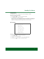
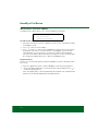
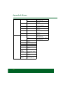
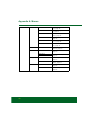
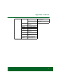
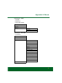
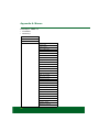
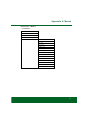
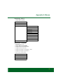
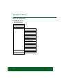
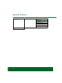
HawkEye Pro
User Manual
www.bearmach.com
Bearmach HawkEye Pro
User Manual
02/2012 - EN(1.0)
Contents
Introduction
Overview....................................................................
Getting Started ........................................................
Additional Vehicle Manufacturers .............................
Kit Contents ............................................................
Display Screen...........................................................
Keypads ....................................................................
Left-hand keypad ....................................................
Right-hand keypad ..................................................
Connection ................................................................
Diagnostic Connector Location................................
Safety Precautions.....................................................
1
2
2
3
4
4
4
4
5
6
7
HawkEye Pro Menus
User Menu ................................................................. 8
DTC Lookup .............................................................. 8
Language Menu......................................................... 9
Self Test Menu........................................................... 9
Software Version Menu............................................ 10
Security Menu.......................................................... 10
iMUX Harness (Firmware update) ............................. 12
Land Rover Systems
Anti-Lock Braking System (ABS) ..............................
Longitudinal Acceleration Sensor Calibration .........
Airbag......................................................................
Restraints Build Mode Entry / Exit..........................
Crash Reset ..........................................................
Air Suspension System (Ride Level Module - RLM) ..
Set Operating Mode ..............................................
Normal Mode ........................................................
Manufacturing Mode .............................................
Set Tolerance Control............................................
Normal Tolerances ................................................
Tighter Tolerances .................................................
Deflation Routines .................................................
Exit Deflate Mode ..................................................
Air Suspension System (EHC2) ................................
Actuators...............................................................
Level Selection ......................................................
13
13
13
13
13
14
14
14
14
14
14
15
15
15
16
16
16
i
Contents
Drive Outputs ......................................................... 16
Set Operating Mode ............................................... 17
Deflation Routines .................................................. 18
Inflation................................................................... 19
Inflation Routines .................................................... 19
Steering Angle Sensor (SAS)..................................... 20
Steering Angle Sensor (SAS) Calibration ................. 20
Longitudinal Acceleration Sensor Calibration .......... 20
Service Reset ........................................................... 20
Service Interval Reset ............................................. 20
Oil Degradation Counter Reset ............................... 20
Electronic Parking Brake (EPB) ................................. 22
Unjam Electronic Parking Brake.............................. 22
Mounting Position................................................... 22
Latching Position.................................................... 23
Longitudinal Accelerometer Calibration................... 23
General Information
Cleaning ................................................................... 25
Display Screen ....................................................... 25
Software Updates..................................................... 25
Specification ............................................................. 25
Declaration of Conformity ......................................... 26
Diagnostic Cables
Cable Identification ................................................... 27
Optional cables ...................................................... 27
Menus
HawkEye Pro Menu Structure................................... 29
Menus - Diesel Engine .............................................. 41
Diesel Engine - TD5................................................ 41
Diesel Engine - Diesel EMS..................................... 42
Diesel Engine - EDC 1.3.1 ...................................... 42
Diesel Engine - DDE 4.0 ......................................... 42
Diesel Engine.......................................................... 43
Diesel Engine - DDE 4.0 ......................................... 43
Diesel Engine - Diesel EMS..................................... 43
Diesel Engine - Diesel EMS..................................... 44
ii
Contents
Menus - Petrol Engine .............................................
Petrol Engine - 14CUX...........................................
Petrol Engine - GEMS............................................
Petrol Engine - EMS 2000 .....................................
Petrol Engine - MEMS 1.9 .....................................
Petrol Engine - MEMS 3 ........................................
Petrol Engine - MS43 ............................................
Petrol Engine - Petrol EMS ....................................
Petrol Engine - M 5.2.1..........................................
Petrol Engine - ME 7.2...........................................
Petrol Engine - Petrol EMS ....................................
Menus - Transmission..............................................
Transmission - JATCO...........................................
Transmission .........................................................
Transmission - GS 8.87.0/1...................................
Transmission - GS 2-38.........................................
Transmission - ZF / EGS 8602...............................
Transmission - GM5 / EGS20 ................................
Transmission .........................................................
Menus - Anti-lock Braking System (ABS) .................
ABS - WABCO ‘D’.................................................
ABS - MK20 / MK25 .............................................
ABS.......................................................................
ABS - WABCO ‘C’.................................................
ABS - Bosch 5.7 ...................................................
ABS.......................................................................
Menus - Airbag ........................................................
Airbag - Autoliv AC4 ..............................................
Airbag - Siemens SRE Smart.................................
Airbag....................................................................
Airbag - TRW SPS.................................................
Airbag - TRW Gen 4 ..............................................
Airbag - TRW MRS 4 .............................................
Airbag....................................................................
Menus - Climate control...........................................
Climate Control......................................................
Climate Control......................................................
Menus - Air Suspension...........................................
Air Suspension - Airsus..........................................
Air Suspension - EHC2..........................................
44
44
45
45
46
47
48
48
48
49
49
50
50
50
50
50
51
52
53
54
54
55
55
56
56
56
57
57
57
57
57
57
58
58
59
59
59
60
60
61
iii
Contents
Menus - Chassis....................................................... 63
Chassis - ACE ........................................................ 63
Chassis .................................................................. 63
Chassis .................................................................. 64
Menus - Security ...................................................... 65
Security - 10AS ...................................................... 65
Security - CCU ....................................................... 66
Security - EWS 3D.................................................. 66
Security .................................................................. 67
Security - BCU ....................................................... 67
Security - GM3 Body Electrics................................ 69
Security - BeCM Body Electronics.......................... 70
Security - GM3 Body Electrics................................ 72
Security - Body ...................................................... 72
Security - VIM......................................................... 72
Menus - Steering Angle Sensor (SAS) ....................... 73
SAS........................................................................ 73
SAS........................................................................ 73
SAS........................................................................ 73
Menus - Service Reset.............................................. 74
Service Reset ......................................................... 74
Service Reset ......................................................... 74
Menus - Electronic Parking Brake (EPB) ................... 75
EPB........................................................................ 75
Menus - Fuel-Burning Heater.................................... 76
Fuel-Burning Heater ............................................... 76
Fuel-Burning Heater ............................................... 76
Menus - Global DTC Clear ........................................ 77
Global DTCs........................................................... 77
iv
Introduction
Introduction
Overview
Nearly every new road vehicle, and many older vehicles, have multiple control modules
that monitor and control different aspects of the vehicle (e.g. Engine, Transmission,
Body, Suspension). The HawkEye Pro service tool has been specifically designed to
connect to, and communicate with, a number of these control modules and allow the
user to extract information (e.g. Diagnostic Trouble Codes) which may aid in the
diagnosis of system problems.
OM1563
The vehicle coverage available on the HawkEye Pro service tool is as follows.
Available vehicle coverage.
• Defender
• Defender (L326)
• Freelander 1
• Freelander 2 (L359)
• Discovery I
• Discovery 2
• Discovery 3
• Discovery 4
• Range Rover Classic
• Range Rover (P38a)
• Range Rover (L322)
• Range Rover Sport (L320)
1
Introduction
Getting Started
Connect the EOBD cable (BA5083) to the HawkEye Pro service tool and the vehicle's
diagnostic connector. Once connected, the current software version number is
displayed.
Unlocking New Manufacturers
A new or updated HawkEye Pro service tool requires a security key to unlock the Land
Rover application and any other specific vehicle manufacturer. To register the HawkEye
Pro service tool, email [email protected] including the serial number of the
unit, extra Vehicle Manufacturer required and contact details.
After obtaining your security key, follow this procedure to unlock the service tool.
1.
2.
3.
4.
5.
Select ‘User Menu’ from the main menu.
Select 'Security' from the user menu.
Select 'Enter Security Key' from the security menu.
Using the and keys, scroll through the alpha/numeric character list.
Confirm each character by pressing the key.
If you make a mistake use the
key and enter the correct character. To re-enter
the code from the beginning, press the key.
6. When prompted to verify the security key, press to confirm.
7. Power down the HawkEye Pro service tool by disconnecting the USB cable from
the tool.
8. Reconnect the USB cable to restart the HawkEye Pro service tool. The screen
should now show a list of the applications included.
Additional Vehicle Manufacturers
To add vehicle manufacturers to the HawkEye Pro service tool, contact your local
supplier.
2
Introduction
Kit Contents
4
1
3
2
OM1666
HawkEye Pro kit
1. HawkEye Pro service tool
2. J1962 cable (BA5083)
3. USB cable
4. Carry case
5. Quick reference guide (not shown)
3
Introduction
Display Screen
The HawkEye Pro service tool screen is a backlit LCD capable of displaying four rows
of text containing up to twenty characters.
Keypads
The HawkEye Pro is operated via the two keypads.
Left-hand keypad
OM1571
Key
Function
Scrolls left and right.
Provides context sensitive help (where available).
Right-hand keypad
OM1570
Key
Function
Scrolls up within a menu or text.
Scrolls down within a menu or text.
Selects a menu option, Continue or Yes.
Exits a menu or No.
4
Introduction
Connection
1
2
OM1568
The HawkEye Pro service tool has a 25-way connector through which it can
communicate to the vehicle via various interface cables. Connection to the specific
system is via either the vehicle's EOBD (J1962) diagnostic socket or by a system specific
connector. Refer to the 'Vehicle Application List' to determine the correct cable.
When connecting the cable to the HawkEye Pro service tool, always secure the cable
with the fixing screws to prevent accidental disconnection during use.
5
Introduction
Diagnostic Connector Location
Connector
Connector Location
J1962
In the driver / passenger
footwell on:
Defender (L316)
Freelander
Discovery I, 2, 3 and 4
Range Rover (P38a)
Range Rover (L322)
Range Rover Sport (L320)
Connector Face View
Under the driver / passenger
seat on:
Defender
14CUX
Behind the driver side kick
panel on:
Discovery I (V8)
Under driver / passenger seat
on:
Range Rover Classic
OM1557
Troubleshooting
If communications cannot be established with the vehicle, follow the procedure below.
1.
2.
3.
4.
Check the correct system was selected from the menu.
Check the correct cable was used against the application list.
Disconnect both ends of the cable and ensure that no pins are bent or snapped.
Reset the control module on the vehicle by turning the ignition OFF and ON,
reconnect the service tool and try again.
If communications still cannot be established, contact the Product Support Team for
further assistance.
6
Introduction
Safety Precautions
The following guidelines are intended to ensure the safety of the operator whilst
preventing damage to the electrical and electronic components fitted to the vehicle.
Equipment - prior to commencing any test procedure on the vehicle, ensure that the
HawkEye Pro service tool, its harnesses and connectors are in good condition.
Polarity - always observe the correct polarity when connecting the HawkEye Pro service
tool to the vehicle battery
Before carrying out testing on a vehicle, the following procedure should always be
observed.
• Check the handbrake/parking brake is on.
• Check that neutral or park is selected.
• Keep test equipment and harnesses away from HT leads.
• Be aware of moving parts.
• Do not run engine in a confined space without adequate ventilation.
7
HawkEye Pro Menus
HawkEye Pro Menus
User Menu
User Menu
Use the and
selection.
1.
OBD DTC Lookup
2.
Language Menu
3.
Tester Setup
4.
Self Test
5.
Software Version
6.
Security
7.
CAN converter
8.
iMux Harness
keys to select the required function and press
to confirm the
For more information, see ‘HawkEye Pro Menu Structure’, page 29.
Note: Press
to return to the main menu.
DTC Lookup
This option is used to look up a DTC description.
Looking up a known DTC
1. Use the
and
keys to move the cursor under the required DTC character,
then using the and keys, change the characters as required.
2. Press the key to confirm the DTC.
3. Press
to return to the user menu.
If the unit recognises the DTC, the screen will display the full description (for example,
P0100 - Mass or Volume Air Flow ‘A’ Circuit).
Where more than one description is available, a separate menu will appear for you to
select the appropriate option.
If a code is not recognised, the message ‘No Text Allocated for this Code’ is displayed.
8
HawkEye Pro Menus
Language Menu
The language menu allows changing of the software language, if available.
Selecting an alternative language
1. Use the and keys to select the required language.
2. Press the key to confirm the selection.
Note: This menu is only enabled when more than one language is installed on the
HawkEye service tool. If no additional languages are installed, the message ‘Not
Enabled’ will be displayed and the display will return to the User Menu.
Self Test Menu
SELF TEST MENU
1.
Full Self Test
2.
Flash Test
3.
Memory Test
4.
IIC Memory Test
5.
Vehicle Com Test
6.
PWM J1850 Test
7.
CAN Comms Test
8.
Key Pad Test
9.
Display Test
10.
Display All Clear
Selecting a test
1. Use the and keys to select the required test.
2. Press to confirm the selection.
3. Follow the on-screen instructions to carry out the specified test.
4. Press the or
key to return to the Self Test menu.
9
HawkEye Pro Menus
Software Version Menu
This menu displays the HawkEye Pro service tool software version number before
displaying a list of all software modules currently loaded onto the service tool, including
their version numbers.
Checking the software version
1. Use the and keys to scroll through the software module list.
2. Press the or
key to return to the Self Test menu.
Security Menu
All of the applications on the HawkEye Pro service tool are ‘locked’ by a security key. To
unlock a particular application, the appropriate security key must be obtained from the
Product Support team and entered into the HawkEye Pro service tool. If the expected
applications are not displayed in the User Menu it could be that the security key has not
been entered or that it has been entered incorrectly.
To examine or enter a security key, enter the ‘Security’ option. The following menu will
be displayed.
SECURITY
1.
Show SecurityKey
2.
Enter SecurityKey
3.
Unit Serial No.
Show SecurityKey
This option displays the SecurityKey on-screen.
1. Select ‘Show SecurityKey’ from the Security menu and press the
2. Press the or
key to return to the Security menu.
If the security key is incorrect, ‘Key is Invalid’ will be displayed. Press the
further information.
10
key.
key for
HawkEye Pro Menus
Enter SecurityKey
This option is used to enter the security key to unlock the functions on the HawkEye Pro
service tool.
1. Select ‘Enter SecurityKey’ from the Security menu and press the key.
2. Using the and keys, scroll through the alpha / numeric character list.
3. Confirm each character by pressing the key.
In the event of a mistake, use the
key and enter the correct character. To reenter the code from the beginning, press the key.
4. When prompted to verify the security key, press the key.
5. Restart the HawkEye Pro service tool either by disconnecting and then
reconnecting the power supply, or by holding down the , , and
keys
simultaneously.
Note: Pressing the
key at any point will display the on-screen instructions.
Note: The key can be pressed at any point to cancel input of the security key. The
original security key will be retained by the HawkEye Pro service tool.
Unit Serial No.
This option displays the serial number of the HawkEye Pro service tool on-screen.
The unit serial number will match the number on the back of the unit and should be
quoted when calling Product Support to ensure efficient resolution of any technical
issues. This number cannot be changed.
1. Select the ‘Unit Serial No.’ option from the Security menu and press the key.
2. Once the unit serial number has been noted, press the key to return to the
Security menu.
11
HawkEye Pro Menus
iMUX Harness (Firmware update)
The iMux harness option allows you to check and update the firmware.
IMUX HARNESS
1.
2.
Get FW Version
Update FW Version
Get FW Version / Boot Mode
1. Select the 'Get FW Version' item to display the current version of the firmware within
the Multiplex system.
2. Press
to return to the User Menu.
3. Press
to return to continue to put the Multiplex system into boot mode ready to
be updated. Follow the on screen instructions. The Multiplex system must be
reprogrammed once the message to re-power the cable has been displayed.
Disconnect the EOBD cable from the power and then reconnect. Now reprogram
by selecting the ‘Update FW version’ option in the Multiplex menu.
Update Firmware
This process should only be performed after the Multiplex system has been placed into
boot mode.
1. Select the 'Update FW Version' item the Multiplex systm will now be updated.
2. A message will be displayed to show the firmware has been updated. Press
to
continue the update process
Note: The update process must be allowed to fully complete once started and the
power must not be interrupted during the update process.
12
Land Rover Systems
Land Rover Systems
Anti-Lock Braking System (ABS)
• Land Rover vehicles
Longitudinal Acceleration Sensor Calibration
This routine is necessary in the following situations.
• The Longitudinal Acceleration Sensor has been replaced.
• The ABS / TC / ESP control module has been replaced.
• The ESP system is not behaving properly as it should. Resetting of this sensor can
sometimes cure erroneous ESP behaviour.
Airbag
• Land Rover Freelander 2 (L359) (2007-)
Restraints Build Mode Entry / Exit
This function is used to place the Airbag / Restraint System in a ‘build mode’, to facilitate
safe maintenance and repairs to be performed without risk of detonation of airbags or
pretensioners. When work has been completed on the system, the Airbag / Restraints
system must be taken out of ‘build mode’ to restore normal operation.
Crash Reset
This option is necessary on vehicles where airbags have been deployed following a
crash. The routine clears the crash ‘flag’ in the Body Control Module to enable normal
operation after repair of the vehicle and installation of a new airbag.
13
Land Rover Systems
Air Suspension System (Ride Level Module - RLM)
• Discovery 3 (2005 - 2009)
• Range Rover Sport (L320) (2005 - 2009)
• Range Rover (L322) (2006 - 2009)
There are several functions available via the HawkEye Pro service tool.
• Set Operating Mode.
• Set Tolerance Control Mode.
• Deflation Routines.
Set Operating Mode
This procedure is used to set the RLM to different modes. Modes can be set under the
‘Configuration’ option of the HawkEye Pro service tool. The current operating mode can
be displayed under the ‘Live Data’ option of the HawkEye Pro service tool.
Pre-test conditions
• The ignition must be ON.
• An approved battery charger must be connected to ensure consistent power supply.
Normal Mode
This is the normal operating mode for the RLM.
Manufacturing Mode
This mode is mainly used in the factory when assembling the vehicle. It can, however,
also be used if the owner of the vehicle wishes to fit coil springs instead of the air springs.
Placing the control module in this mode ensures that the control module continues to
function in terms of processing information such as height information. This process will
render the Air Suspension controls and instruments non-functional.
Note: If the vehicle is driven in any mode other than Normal Mode, the Air Suspension
will NOT operate correctly.
Set Tolerance Control
This procedure is used to set the RLM tolerance control. Tolerance control can be set
under the ‘Configuration’ option of the HawkEye Pro service tool. The current tolerance
control state can be displayed under the ‘Live Data’ option of the HawkEye Pro service
tool.
Pre-test conditions
• The ignition must be ON.
• An approved battery charger must be connected to ensure consistent power supply.
Normal Tolerances
This state is the normal operating mode for the Air Suspension system.
14
Land Rover Systems
Tighter Tolerances
This state is used when another part of the vehicle is being aligned or calibrated. The
two main instances where this state is used are:
• Wheel alignment;
• Adaptive Headlamp calibration.
Deflation Routines
There are several routines available for this system.
• Deflate air springs
• Deflate reservoir
• Deflate all (air springs and reservoir)
• Exit deflate mode.
These routines are to be used when work must be carried out on the air suspension
system; this will reduce the risk of personal injury caused by compressed air.
Pre-test conditions:
• The ignition must be ON;
• An approved battery charger must be connected to ensure consistent power supply.
Caution: The vehicle will lower during deflation of the air suspension. To avoid
damage, ensure all doors are closed.
Warning: It is the responsibility of the technician to ensure that air has been fully
expelled from the air suspension system even if the HawkEye Pro service tool
indicates that the routine has completed successfully. The procedure may need
to be run more than once to ensure all air is expelled from the system. Failure to
do so may result in personal injury.
Exit Deflate Mode
After the work has been completed the technician must re-enable the system using the
‘Exit Deflate Mode’ option to restore normal operation of the air suspension system.
15
Land Rover Systems
Air Suspension System (EHC2)
• Range Rover (L322) (2002 - 2006)
There are four functions available via the HawkEye Pro service tool for the EHC2 air
suspension system.
• Actuators
• Set Operating Mode
• Set Tolerance Control Mode
• Deflation Routines
Actuators
There are a number of actuators available on the HawkEye Pro service tool. These are
split into two different sections.
Level Selection
The HawkEye Pro service tool can be used to force the air suspension system to any
level as an alternative to using the ride height switch inside the vehicle.
• Access Level.
• Motorway Level.
• Standard Level.
• Off-road Level.
These are useful for the diagnosis of faults with the ride height switch and wiring.
Pre-test conditions:
• The engine must be RUNNING.
Drive Outputs
The following outputs can be driven individually using the HawkEye Pro service tool.
• Front right valve
• Front left valve
• Rear right valve
• Rear left valve
• Exhaust valve
• Reservoir valve
• Compressor valve
• High-pressure exhaust valve
• Front cross-link valve
• Rear cross-link valve
• Access LED
• Motorway LED
16
Land Rover Systems
• Standard LED
• Off-road LED
• Hold LED
Pre-test conditions
• The ignition must be ON and the engine OFF.
Set Operating Mode
There are four functions available via the HawkEye Pro service tool for the EHC2 system.
• Transport mode
• Low Tolerance Mode (used during wheel alignment or headlamp levelling)
• Production Mode (used to disable all control circuits within the system)
• Normal Mode (to cancel all of the above).
There procedures are used to set the control module to different modes. Modes can be
set under the ‘Service Functions’ option of the HawkEye Pro service tool. The current
operating mode can be displayed under the ‘Live Data’ option of the HawkEye Pro
service tool.
Pre-test conditions
• The ignition must be ON.
• An approved battery charger must be connected to ensure consistent power supply.
Note: If the vehicle is driven in any mode other than ‘Normal Mode’, the air suspension
will not operate correctly.
17
Land Rover Systems
Deflation Routines
There are seven routines available for this system.
• Deflate right front
• Deflate left front
• Deflate right rear
• Deflate left rear
• Deflate front
• Deflate rear
• Deflate all
These routines for use prior to servicing the air suspension system to reduce the risk of
injury by compressed air.
Pre-test conditions
• The ignition must be ON.
• An approved battery charger must be connected to ensure consistent power supply.
Caution: The vehicle will lower during deflation of the air suspension. To avoid
damage, ensure all doors are closed.
Warning: It is the responsibility of the technician to ensure that air has been fully
expelled from the air suspension system even if the HawkEye Pro service tool
indicates that the routine has completed successfully. The procedure may need
to be run more than once to ensure all air is expelled from the system. Failure to
do so may result in personal injury.
18
Land Rover Systems
Inflation
When work has been completed on the specified area the air suspension can be reinflated either by selecting the corresponding ‘Inflation’ routine or by starting the engine.
When the engine is running, the system will inflate the four corners to the correct height
for the currently selected level.
Inflation Routines
There are seven routines available for this system.
• Inflate right front
• Inflate left front
• Inflate right rear
• Inflate left rear
• Inflate front
• Inflate rear
• Inflate all
These routines are to be used either when work has been completed on a section of the
air suspension system or to try and level the vehicle in an emergency repair situation.
Caution: The vehicle will raise during inflation of the air suspension. To avoid
damage, ensure all doors are closed.
Pre-test conditions
• The ignition must be ON.
• An approved battery charger must be connected to ensure consistent power supply.
Note: These routines may need to be repeated more than once to completely inflate the
specified area.
19
Land Rover Systems
Steering Angle Sensor (SAS)
• Land Rover vehicles
Steering Angle Sensor (SAS) Calibration
The SAS can be calibrated by using the ‘SAS Calibration’ option and following the onscreen instructions.
Note: The SAS should be calibrated after performing any wheel alignment, suspension
adjustment or steering column replacement procedure.
Longitudinal Acceleration Sensor Calibration
This routine is necessary in the following situations.
• The longitudinal acceleration sensor has been replaced.
• The ABS / TC / ESP control module has been replaced.
• The ESP system is malfunctioning. Resetting of this sensor can sometimes cure ESP
malfunction.
Service Reset
• Check application list for vehicles covered.
There are two service reset options available for Land Rover.
Service Interval Reset
This option resets the conventional service interval indicator. This function is to be used
after a full service has been completed on the vehicle.
Oil Degradation Counter Reset
This option is necessary on vehicles which have Diesel Particulate Filters (DPF) fitted.
This is not necessary on vehicles with petrol or LPG engines or for diesel engines where
a DPF is not fitted. The counter should only be reset after the oil has been changed.
20
Land Rover Systems
Manual Service Reset
• Range Rover (L322) (2002 - 2009) (except Japan and North America)
1. Switch ignition OFF.
A
OM1257
2. Press and hold button A.
3. Keep button depressed and switch the ignition to position I.
4. Keep button depressed for five seconds until ‘SIA RESET’ appears in the LCD
display.
5. The display will now indicate the distance to service and the type of service required
(OIL SERVICE or INSPECTION).
6. Check the distance to service has been reached. If it hasn’t, please proceed to the
next step. If it has, please proceed to step 9.
7. Press button A once. The display will show the date to service.
8. Check the service date has been reached. If it has not, please proceed to step 10.
If it has, please proceed to step 11.
9. When the distance to service has been reached, press button A for 5 seconds.
‘RESET’ will flash on the display. Press button A again before ‘RESET’ has flashed
5 times to reset the service distance limit. The new distance to service will be
displayed for 5 seconds before the service date is displayed.
10. Press button A once to end the service interval check and reset.
11. When the date for service limit has been reached, press and hold button A for 5
seconds. ‘RESET’ will flash on the display. Press button A again before ‘RESET’
has flashed 5 times to reset the service date limit. The new date to service will be
displayed for 5 seconds before end service is displayed.
12. Switch ignition OFF.
21
Land Rover Systems
Electronic Parking Brake (EPB)
• Discovery 3 (2005 - 2009)
• Range Rover Sport (L320) (2005 - 2009)
• Range Rover (L322) (2006 - 2009)
There are four functions available under the ‘Service Brakes’ menu.
Unjam Electronic Parking Brake
This procedure should be used if one of the parking brake cables becomes detached or
breaks whilst the vehicle is being driven.
Pre-test conditions
• The vehicle must be stationary.
• The engine must be RUNNING and at IDLE speed.
After performing the procedure it is necessary for the technician to carry out checks on
the condition of the rear brake shoes and drums. If both are satisfactory, the technician
should then refer to the Land Rover technical information.
Note: Part of this procedure places the parking brake into ‘Mounting Position’. In
‘Mounting Position’ a red flashing light will appear in the instrument cluster. It does not
indicate a vehicle fault.
Mounting Position
The parking brake must be driven into the ‘Mounting Position’ if any of the following
procedures are to be performed.
• Parking brake shoes removal or installation
• Parking brake shoe and lining adjustment
Note: This procedure must be carried out if new parking brake shoes are fitted, new
rear brake discs are fitted or if the vehicle has been mud wading for more than 50
miles.
• Changing parking brake cables
• Parking brake actuator removal or installation (to ensure parking brake cables can be
connected and disconnected)
22
Land Rover Systems
Pre-test conditions
• The vehicle must be stationary.
• The ignition must be ON.
• An approved battery charger must be connected to ensure consistent power supply.
Ensure the on-screen instructions are followed precisely.
To exit the ‘Mounting Position’ mode, switch the parking brake on and then off, twice.
Note: This procedure places the parking brake into ‘Mounting Position’. In ‘Mounting
Position’ a red flashing light will appear in the instrument cluster. It does not indicate a
vehicle fault.
Latching Position
This procedure may be required after use of the parking brake emergency release in
order to relatch the parking brake.
Pre-test conditions
• The vehicle must be stationary.
• The ignition must be ON.
• An approved battery charger must be connected to ensure consistent power supply.
Ensure the on screen instructions on the service tool are followed precisely and in the
correct order.
Longitudinal Accelerometer Calibration
This procedure may be necessary if the longitudinal accelerometer has been replaced.
Pre-test conditions
• The ignition must be ON.
• An approved battery charger must be connected to ensure consistent power supply.
• Ensure the vehicle is placed on a level surface and remains stationary throughout the
calibration procedure.
• Ensure the parking brake module is secured to the vehicle and that the parking brake
is applied.
Ensure the on-screen instructions are followed precisely.
23
Land Rover Systems
Electronic Parking Brake (EPB) - Disabling Manually
This procedure is necessary before carrying out work on the rear brake discs. When
performed correctly, the brake caliper pistons are retracted by the control module.
1.
2.
3.
4.
5.
6.
7.
Switch the ignition ON.
Apply and hold the footbrake.
Apply and hold the parking brake switch in the RELEASE position.
Turn the ignition OFF and remove the key (where applicable).
Release the footbrake.
Release the parking brake switch.
Remove fuse number 8 from the fuse box to isolate the parking brake electrical
circuit.
Electronic Parking Brake (EPB) - Enabling Manually
1. Install fuse number 8 into the fuse box to re-enable the parking brake electrical
circuit.
Electronic Parking Brake (EPB) Shoes - Bedding In
This procedure must be carried out if new parking brake shoes are fitted, new rear brake
discs are fitted or if the vehicle has been mud wading for more than 50 miles.
1. Switch engine ON.
2. Apply the footbrake 3 times within 10 seconds and hold applied after the third
application.
3. Apply the parking brake 4 times and release it 3 times within 10 seconds to enter
‘Service Bedding In Procedure Mode’.
Note: The ‘Service Bedding In Procedure Mode’ will remain active until the next
ignition cycle or until the vehicle speed exceeds 31mph (50km/h). If it deactivates,
repeat steps 1-3 to re-activate ‘Service Bedding In Procedure Mode’.
4. Conduct 10 stops from 19 - 22mph (30 - 35km/h) to bed-in the parking brake
linings.
Note: The parking brake force will be increased to the dynamic maximum as long
as the switch is held in the applied position.If the switch is released then the parking
brake will be released.
Caution: The EPB must be allowed to cool between each application. The
EPB can be cooled either by driving for 500 yards (500 metres) at 19 22mph (30 - 35 kmh) or by remaining stationary for 1 minute without
activating the parking brake switch.
24
General Information
General Information
Cleaning
To maintain the condition and serviceability of the service tool, it is advisable to follow
the cleaning procedures below.
Caution: Never use solvents or other harsh cleaning fluids to clean the HawkEye
Pro service tool. Harsh solvents may seriously damage the plastic casing.
Caution: The HawkEye Pro service tool is not waterproof. Always dry the unit
thoroughly after cleaning or if it has been subject to accidental spillage.
It is recommended that the following parts of the HawkEye Pro service tool are
periodically inspected and cleaned as required.
• The case
• The display screen
• The keypad
• Adapter cables and connectors
To clean the HawkEye Pro service tool, or any of its cables or connectors, apply a mild
detergent solution to a soft clean cloth.
Caution: Before cleaning, disconnect the service tool from the vehicle or any
other power source.
Display Screen
During normal everyday use, the screen may become dusty or covered in grime. To
clean the screen, always use a soft, clean, antistatic cloth. If any stubborn stains or
marks remain, use a non-abrasive glass cleaner applied to a soft, clean cloth. Gently
wipe the cloth across the display until the marks have been removed.
Software Updates
Software updates can be loaded onto the service tool by connecting it to a PC. The
cable to connect the service tool to the PC will be supplied along with the upgrade CD
or via the internet. Full instructions for loading the software updates to the service tool
will also be supplied with the upgrade.
Specification
HawkEye Pro complies with ISO/DIS 15031 Part 4 as an EOBD service tool.
Voltage Requirements - 8.0 volts to 16.0 volts DC.
Current requirement - 750mA maximum.
Display - 20 characters by 4 lines LCD with LED back light.
Operating temperature range - 0°C to 50°C
25
General Information
Declaration of Conformity
The HawkEye Pro tool is CE marked and complies with the following directives.
• EN55022:1998 - ITE Emissions (Class A)
• EN50082-1:1998 - Generic EMC Immunity
• EN60950:1992 - Safety Requirements
• FCC47 Part 15 - Radio Frequency Devices (Class A)
A copy of the Declaration of Conformity certificate is available on request from the
manufacturer or your supplier.
26
Diagnostic Cables
Diagnostic Cables
Cable Identification
Optional cables
OM1572
BA5804
27
Appendix A: Menus
Menus
HawkEye Pro Menu Structure
The table below details the HawkEye service tool main menu structure.
Defender
EMS
ABS
Defender
(L316)
Discovery I
CUX14
See ‘Petrol Engine 14CUX’, page 44
GEMS
See ‘Petrol Engine - GEMS’,
page 45
TD5
See ‘Diesel Engine - TD5’,
page 41
WABCO ‘D’
See ‘ABS - WABCO ‘D’’,
page 54
‘Security - 10AS’, page 65
Security
10AS
EMS
See ‘Diesel Engine Diesel EMS’, page 42
ABS
WABCO ‘D’
See ‘ABS - WABCO ‘D’’,
page 54
Security
10AS
See ‘Security - 10AS’,
page 65
EMS
CUX14
See ‘Petrol Engine 14CUX’, page 44
GEMS
See ‘Petrol Engine - GEMS’,
page 45
MEMS 1.9
See ‘Petrol Engine - MEMS
1.9’, page 46
EDC 1.3.1
See ‘Diesel Engine - EDC
1.3.1’, page 42
ABS
WABCO ‘C’
See ‘ABS - WABCO ‘C’’,
page 56
Airbag
TRW SPS
See ‘Airbag - TRW SPS’,
page 57
Security
10AS
See ‘Security - 10AS’,
page 65
29
Appendix A: Menus
Discovery II
Discovery 3
EMS
M 5.2.1
See ‘Petrol Engine - M
5.2.1’, page 48
TD5
See ‘Diesel Engine - TD5’,
page 41
Transmission
GS8.87.0/1
See ‘Transmission - GS
8.87.0/1’, page 50
ABS
WABCO ‘D’
See ‘ABS - WABCO ‘D’’,
page 54
Airbag
TRW Gen 4
See ‘Airbag - TRW Gen 4’,
page 57
Security
BCU
See ‘Security - BCU’,
page 67
Chassis
ACE (ROCK / ARC)
See ‘Chassis - ACE’,
page 63
EMS
Petrol
See ‘Petrol Engine - Petrol
EMS’, page 49
Diesel
See ‘Diesel Engine - Diesel
EMS’, page 43
Transmission
See ‘Transmission’,
page 53
ABS
See ‘ABS’, page 56
Airbag
See ‘Airbag’, page 58
EPB
See ‘EPB’, page 75
Service Reset See ‘Service Reset’,
page 74
30
Steering
Angle
See ‘SAS’, page 73
Security
See ‘Security - Body’,
page 72
Chassis
See ‘Chassis’,
page 63
Fuel-Burning
Heater
See ‘Fuel-Burning
Heater’, page 76
Appendix A: Menus
Discovery 4
EMS
Petrol
See ‘Petrol Engine - Petrol
EMS’, page 49
Diesel
See ‘Diesel Engine - Diesel
EMS’, page 43
Transmission
ZF HP26
ZF HP28
See ‘Transmission’, page 53
ABS
See ‘ABS’, page 56
Airbag
See ‘Airbag’, page 58
Climate
control
See ‘Climate Control’,
page 59
EPB
See ‘EPB’, page 75
Body
electrics
See ‘Security - Body’,
page 72
Service Reset See ‘Service Reset’,
page 74
Immob.
(Steer.Lock)
See ‘Security - VIM’,
page 72
Chassis
See ‘Chassis’,
page 63
Fuel-Burning
Heater
See ‘Fuel-Burning
Heater’, page 76
HSCAN Clear
DTCs
See ‘Global DTCs’,
page 77
MSCAN
Clear DTCs
See ‘Global DTCs’,
page 77
31
Appendix A: Menus
Freelander 1
EMS
MEMS 1.9
See ‘Petrol Engine - MEMS
1.9’, page 46
MEMS 3
See ‘Petrol Engine - MEMS
3’, page 47
EMS 2000
See ‘Petrol Engine - EMS
2000’, page 45
MS43
See ‘Petrol Engine - MS43’,
page 48
EDC 1.3.1
See ‘Diesel Engine - EDC
1.3.1’, page 42
DDE 4.0
See ‘Diesel Engine - DDE
4.0’, page 42
Transmission
JATCO
See ‘Transmission JATCO’, page 50
ABS
WABCO ‘D’
See ‘ABS - WABCO ‘D’’,
page 54
ABS MK20
See ‘ABS - MK20 / MK25’,
page 55
ABS MK25
Airbag
Security
32
Autoliv AC4
See ‘Airbag - Autoliv AC4’,
page 57
Siemens SRE Smart
See ‘Airbag - Siemens SRE
Smart’, page 57
CCU
See ‘Security - CCU’,
page 66
EWS 3D
See ‘Security - EWS 3D’,
page 66
Appendix A: Menus
Freelander 2
EMS
Petrol
See ‘Petrol Engine - Petrol
EMS’, page 48
Diesel
See ‘Diesel Engine’,
page 43
Transmission
See ‘Transmission’,
page 50
ABS
See ‘ABS’, page 55
Airbag
See ‘Airbag’, page 57
Climate
control
See ‘Climate Control’,
page 59
Service Reset See ‘Service Reset’,
page 74
SASM
See ‘SAS’, page 73
Security
See ‘Security’,
page 67
Fuel-Burning
Heater
See ‘Fuel-Burning
Heater’, page 76
33
Appendix A: Menus
Range Rover
(L322)
02MY - 05MY
EMS
Transmission
Petrol
See ‘Petrol Engine - ME
7.2’, page 49
Diesel
See ‘Diesel Engine - DDE
4.0’, page 43
Petrol
See ‘Transmission - ZF /
EGS 8602’, page 51
Diesel
See ‘Transmission - GM5 /
EGS20’, page 52
ABS
See ‘ABS - Bosch
5.7’, page 56
Airbag
See ‘Airbag - TRW
MRS 4’, page 58
Climate
control
See ‘Climate Control’,
page 59
Body
Electrics
See ‘Security - GM3
Body Electrics’,
page 69
Service Reset See ‘Service Reset’,
page 74
34
Steering
Angle Sensor
See ‘SAS’, page 73
Security
See ‘Security - EWS
3D’, page 66
Air
Suspension
See ‘Air Suspension EHC2’, page 61
Fuel-Burning
Heater
See ‘Fuel-Burning
Heater’, page 76
Appendix A: Menus
Range Rover
(L322)
06MY
EMS
Transmission
ABS
Petrol
See ‘Petrol Engine - Petrol
EMS’, page 49
Diesel
See ‘Diesel Engine - DDE
4.0’, page 43
Petrol
See ‘Transmission’, page 53
Diesel
See ‘Transmission’, page 53
Petrol
See ‘ABS’, page 56
Diesel
See ‘ABS - Bosch 5.7’,
page 56
Airbag
See ‘Airbag - TRW
MRS 4’, page 58
Climate
control
See ‘Climate Control’,
page 59
Service Reset See ‘Service Reset’,
page 74
Body
Electrics
See ‘Security - GM3
Body Electrics’,
page 69
Steering
Angle Sensor
Petrol
See ‘SAS’, page 73
Diesel
See ‘SAS’, page 73
Security
See ‘Security - GM3
Body Electrics’,
page 69
Air
Suspension
See ‘Chassis’,
page 63
Fuel-Burning
Heater
See ‘Fuel-Burning
Heater’, page 76
35
Appendix A: Menus
Range Rover
(L322)
07- 09 MY
EMS
Petrol
See ‘Petrol Engine - Petrol
EMS’, page 49
Diesel
See ‘Diesel Engine - Diesel
EMS’, page 43
Transmission
See ‘Transmission’,
page 53
ABS
See ‘ABS’, page 56
Airbag
See ‘Airbag’, page 58
EPB
See ‘EPB’, page 75
Service Reset See ‘Service Reset’,
page 74
36
Steering
Angle Sensor
‘SAS’, page 73
Body
Electrics
See ‘Security - GM3
Body Electrics’,
page 69
Chassis
See ‘Chassis’,
page 63
Fuel-Burning
Heater
See ‘Fuel-Burning
Heater’, page 76
Appendix A: Menus
Range Rover
(L322) 10 MY
EMS
Petrol
See ‘Petrol Engine - Petrol
EMS’, page 49
Diesel
See ‘Diesel Engine - Diesel
EMS’, page 43
Transmission
See ‘Transmission’,
page 53
ABS
See ‘ABS’, page 56
Airbag
See ‘Airbag’, page 58
Climate
control
See ‘Climate Control’,
page 59
EPB
See ‘EPB’, page 75
Steering
angle
See ‘SAS’, page 73
Body
electrics
See ‘Security - Body’,
page 72
Service Reset See ‘Service Reset’,
page 74
Immob.
(Steer.Lock)
See ‘Security - VIM’,
page 72
Chassis
See ‘Chassis’,
page 64
Fuel-Burning
Heater
See ‘Fuel-Burning
Heater’, page 76
HSCAN Clear
DTCs
See ‘Global DTCs’,
page 77
MSCAN
Clear DTCs
See ‘Global DTCs’,
page 77
37
Appendix A: Menus
Range Rover
(P38a)
EMS
Transmission
ABS
Airbag
Range Rover
Classic
38
M 5.2.1
See ‘Petrol Engine - M
5.2.1’, page 48
GEMS
See ‘Petrol Engine - GEMS’,
page 45
EDC 1.3.1
See ‘Diesel Engine - EDC
1.3.1’, page 42
GS8.87.0/1
See ‘Transmission - GS
8.87.0/1’, page 50
GS2-38
See ‘Transmission - GS
2-38’, page 50
WABCO ‘C’
See ‘ABS - WABCO ‘C’’,
page 56
WABCO ‘D’
See ‘ABS - WABCO ‘D’’,
page 54
TRW SPS
See ‘Airbag - TRW SPS’,
page 57
TRW Gen 4
See ‘Airbag - TRW Gen 4’,
page 57
Climate
control
See ‘Climate Control’,
page 59
Chassis
Air Suspension
Body
electrics BeCM
See ‘Security - BeCM
Body Electronics’,
page 70
EMS
14CUX
See ‘Petrol Engine 14CUX’, page 44
Chassis
Air Suspension
See ‘Climate Control’,
page 59
See ‘Climate Control’,
page 59
Appendix A: Menus
Range Rover
Sport
(L320) - 06 - 09
MY
EMS
Petrol
See ‘Petrol Engine - Petrol
EMS’, page 49
Diesel
See ‘Diesel Engine - Diesel
EMS’, page 43
Transmission
See ‘Transmission’,
page 53
ABS
See ‘ABS’, page 56
Airbag
See ‘Airbag’, page 58
Climate
control
See ‘Climate Control’,
page 59
EPB
See ‘EPB’, page 75
Service Reset See ‘Service Reset’,
page 74
Steering
Angle Sensor
See ‘SAS’, page 73
Security
See ‘Security - Body’,
page 72
Chassis
See ‘Chassis’,
page 63
Fuel-Burning
Heater
See ‘Fuel-Burning
Heater’, page 76
39
Appendix A: Menus
Range Rover
Sport (L320) 10
MY
EMS
Petrol
See ‘Petrol Engine - Petrol
EMS’, page 49
Diesel
See ‘Diesel Engine - Diesel
EMS’, page 43
Transmission
See ‘Transmission’,
page 53
ABS
See ‘ABS’, page 56
Airbag
See ‘Airbag’, page 58
Climate
control
See ‘Climate Control’,
page 59
EPB
See ‘EPB’, page 75
Body
electrics
See ‘Security - Body’,
page 72
Service Reset See ‘Service Reset’,
page 74
40
Immob.
(Steer.Lock)
See ‘Security - VIM’,
page 72
Chassis
See ‘Chassis’,
page 63
Fuel-Burning
Heater
See ‘Fuel-Burning
Heater’, page 76
HSCAN Clear
DTCs
See ‘Global DTCs’,
page 77
MSCAN
Clear DTCs
See ‘Global DTCs’,
page 77
Appendix A: Menus
Menus - Diesel Engine
Diesel Engine - TD5
• Defender
• Discovery II
Read Faults / DTCs
Clear Faults / DTCs
Live Data
Circuit Tests
Injector 1 Test
Injector 2 Test
Injector 3 Test
Injector 4 Test
Injector 5 Test
CM Check
EGR Vacuum Mod
EGR Inlet Thrott.
Turbo Wastegate
MI Lamp
Glow Plug Lamp
Glow Plug Relay
Tachometer
Temperature Gauge
Fuel Pump
A/C Clutch Drive
Fan(s) Test
Programming
Immobilisation
Immob. NOT Fitted
Immob. Fitted
Read Injector
Set Injector
Injector 1
Injector 2
Injector 3
Injector 4
Injector 5
Set Throttle
Throttle 2 Track
Throttle 3 Track
41
Appendix A: Menus
Diesel Engine - Diesel EMS
• Defender (L316) (2007 -)
Read Faults / DTCs
Clear Faults / DTCs
Live Data
Circuit Tests
Diesel Engine - EDC 1.3.1
• Freelander 1
• Discovery I
• Range Rover (P38a)
Read Faults / DTCs
Clear Faults / DTCs
Live Data
Circuit Tests
Engine Stop
Boost Pres Wasteg
A/Con. Comp. Relay
EGR Valve
Pre-Heater Relay
Pre-Heater W/Lamp
Diagnostic Lamp
Fuel Pump
Read CM Details
Security code
Diesel Engine - DDE 4.0
• Freelander 1
Read Faults / DTCs
Clear Faults / DTCs
Live Data
Actuators
Aircon Clutch
Glow Plug Relay
EGR Vacuum Mod
Cooling Fan
42
Appendix A: Menus
Diesel Engine
• Freelander 2 (L359)
Read Faults / DTCs
Clear Faults / DTCs
Live Data
Oil Change
ECM Data
Diesel Engine - DDE 4.0
• Range Rover (L322) (2002 - 2006)
Read Faults / DTCs
Clear Faults / DTCs
Live Data
ECM Data
Actuators
EGR Control
Pre-Supply Pump
Glow Time Relay
Charge Air Control
Cooling Fan
Diesel Engine - Diesel EMS
• Discovery 3
• Range Rover (L322) (2007 - 2009)
• Range Rover Sport (L320)
Read Faults / DTCs
Clear Faults / DTCs
Live Data
ECM Data
43
Appendix A: Menus
Diesel Engine - Diesel EMS
• Discovery 4 (L319) 2010 MY
• Range Rover (L322) 2010MY
• Range Rover Sport (L320)2010 MY
Read Faults / DTCs
Clear Faults / DTCs
Live Data
ECM Data
Menus - Petrol Engine
Petrol Engine - 14CUX
• Defender
• Discovery I
• Range Rover Classic
Read Faults / DTCs
Clear Faults / DTCs
Live Data
Actuators
Injectors
Fuel Pump
Learn security
Configuration
44
Reset adaptions
Appendix A: Menus
Petrol Engine - GEMS
• Defender
• Discovery I
• Range Rover (P38a)
Read Faults / DTCs
Clear Faults / DTCs
Live Data
Actuators
MI Lamp
Fuel Pump
Purge Valve
Petrol Engine - EMS 2000
• Freelander 1
Read Faults / DTCs
Clear Faults / DTCs
Live Data
Actuators
Main Relay
Injector 1
Injector 2
Injector 3
Injector 4
Injector 5
Injector 6
Fuel Pump Relay
A/C Clutch
Cooling Fan Relay
Purge Canister
Over Speed Relay
Stepper Motor
Prime Fuel Line
VIS Balance
VIS Butterfly
ECM Data
45
Appendix A: Menus
Petrol Engine - MEMS 1.9
• Freelander 1
• Discovery I
Read Faults / DTCs
Clear Faults / DTCs
Live Data
Actuators
Temperature Gauge
Fuel Pump
PTC Heater
Air Conditioning
Idle Solenoid
ORFCO Solenoid
Pulse Air Valve
EGR Valve
Purge Valve
O2 Sensor Heater
Emiss. Fail Lamp
Turbo Boost Cont
Fuel Used
Fan Control 1
Fan Control 2
VVT - Inc Period
Back Pres. Valve
Var. Geom. Inlet
Anti RunOn Valve
Tachometer
Boost Gauge
SW Throttle Sw
VVT - Dec Period
Fan Control 3
Test Ign. Coils
Injectors
Ambient Air Lamp
Cruis Dis Relay
Hill Desc Relay
RevLite-Caterham
46
Appendix A: Menus
Petrol Engine - MEMS 3
• Freelander 1
Read Faults / DTCs
Clear Faults / DTCs
Live Data
ECM Data
Actuators
Main Relay
Fuel Pump Relay
MI Lamp
A/C Clutch
Radiator Fan
Auxiliary Fan
US O2 Heater
DS O2 Heater
Engine Bay Fan
Warning Lamp
Tachometer
Injector 1
Injector 2
Injector 3
Injector 4
47
Appendix A: Menus
Petrol Engine - MS43
• Freelander 1
Read Faults / DTCs
Clear Faults / DTCs
Live Data
ECM Data
Actuators
Cooling Fan
Fuel Pump
DMTL Pump
DMTL Valve
DMTL Heater
Purge Valve
A/C Clutch
MI Lamp
Petrol Engine - Petrol EMS
• Freelander 2 (L359)
Read Faults / DTCs
Clear Faults / DTCs
Live Data
ECM Data
Petrol Engine - M 5.2.1
• Discovery II
• Range Rover (P38a)
Read Faults / DTCs
Clear Faults / DTCs
Live Data
ECM Data
Actuators
Fuel Pump
Condenser Fan
CVS Valve
E Box Fan
48
Appendix A: Menus
Petrol Engine - ME 7.2
• Range Rover (L322)
Read Faults / DTCs
Clear Faults / DTCs
Live Data
Actuators
Fuel Injector 1
Fuel Injector 2
Fuel Injector 3
Fuel Injector 4
Fuel Injector 5
Fuel Injector 6
Fuel Injector 7
Fuel Injector 8
Map Thermostat
Tank Vent. Valve
A/C Compressor
ECM Data
Petrol Engine - Petrol EMS
• Discovery 3 (L319)
• Range Rover (L322) (2006)
• Range Rover (L322) 2007-2009
• Range Rover (L322) 2010
• Range Rover Sport (L320) 2006 - 2009
• Range Rover Sport (L320) 2010
• Discovery 4 (L319) 2010
Read Faults / DTCs
Clear Faults / DTCs
Live Data
ECM Data
49
Appendix A: Menus
Menus - Transmission
Transmission - JATCO
• Freelander 1
Read Faults / DTCs
Clear Faults / DTCs
Live Data
Transmission
• Freelander 2 (L359)
Read Faults / DTCs
Clear Faults / DTCs
Live Data
ECM Data
Transmission - GS 8.87.0/1
• Discovery II
• Range Rover (P38a)
Faults Codes / DTCs
Read Faults / DTCs
Clear Faults / DTCs
Live Data
ECM Data
Transmission - GS 2-38
• Range Rover (P38a)
Faults Codes / DTCs
Read Faults / DTCs
Clear Faults / DTCs
Live Data
ECM Data
50
Appendix A: Menus
Transmission - ZF / EGS 8602
• Range Rover (L322) (2002 - 2005)
Read Faults / DTCs
Clear Faults / DTCs
Live Data
Actuators
Solenoid Valve 1
Solenoid Valve 2
Solenoid Valve 3
Pressure Act. 1
Pressure Act. 2
Pressure Act. 3
Pressure Act. 4
Pressure Act. 5
Shiftlock
Instruments
ECM Data
51
Appendix A: Menus
Transmission - GM5 / EGS20
• Range Rover (L322) (2002 - 2006)
Read Faults / DTCs
Clear Faults / DTCs
Live Data
Actuators
Pressure Act. 1
Pressure Act. 4
Solenoid Valve 1
Solenoid Valve 2
Solenoid Valve 3
Shiftlock
Reversing Light
Eng. Intervention
Park (P) Lamp
Reverse (R) Lamp
Neutral (N) Lamp
Drive (D) Lamp
1st Gear (1) Lamp
2nd Gear (2) Lamp
3rd Gear (3) Lamp
4th Gear (4) Lamp
5th Gear (5) Lamp
Sport (S) Lamp
Economy (E) Lamp
Manual (M) Lamp
Economy (A) Lamp
Fault Indication
ECM Data
52
Appendix A: Menus
Transmission
• Discovery 3 (L319)
• Discovery 4 (L319) 2010 ZF HP26 / ZF HP28
• Range Rover Petrol (L322) 2006
• Range Rover (L322) 2007 - 2009
• Range Rover (L322) 2010
• Range Rover Sport (L320) 2006 - 2009
• Range Rover Sport (L320) 2010
Read Faults / DTCs
Clear Faults / DTCs
Live Data
ECM Data
53
Appendix A: Menus
Menus - Anti-lock Braking System (ABS)
ABS - WABCO ‘D’
• Defender
• Defender (L316) (2007 -)
• Freelander 1
• Discovery II
• Range Rover (P38a)
Read Faults / DTCs
Clear Faults / DTCs
Live Data
Circuit Tests
Inlet Valve RF
Outlet Valve RF
Wheel Test RF
Hydraulics RF
Inlet Valve LF
Outlet Valve LF
Wheel Test LF
Hydraulics LF
Inlet Valve RR
Outlet Valve RR
Wheel Test RR
Hydraulics RR
Inlet Valve LR
Outlet Valve LR
Wheel Test LR
Hydraulics LR
Supplies / Grounds
ABS Warning Lamp
TC Warning Light
Brake Warn. Lamp
Shuttle Valve Sw.
Valve Relay
Pump Relay
HDC Info. Light
54
Appendix A: Menus
Circuits Tests (continued)
HDC Fault Light
Brake Light Relay
Speedometer
SLS RR Valve
SLS LR Valve
SLS Exhaust Valve
SLS Cmpress Relay
SLS RR Height
SLS LR Height
SLS Audible Warn
SLS Warning Light
OFF Road Light
TC Valve NC
TC Valve NO
Isolation Inlet
Rough Road Signal
Programming
Configuration
Transportation
ABS - MK20 / MK25
• Freelander 1
Read Faults / DTCs
Clear Faults / DTCs
Live Data
ABS
• Freelander 2 (L359)
Read Faults / DTCs
Clear Faults / DTCs
Live Data
Configuration
SAS Calibration
Long. Accel. Calib.
ECM Data
55
Appendix A: Menus
ABS - WABCO ‘C’
• Discovery I
• Range Rover (P38a)
Read Faults / DTCs
Clear Faults / DTCs
Live Data
Circuit Tests
ABS Warning Lamp
ETC Info Lamp
Wheel Test LF
Wheel Test LR
Wheel Test RF
Wheel Test RR
Ignition Valves
ETC Valves
ABS - Bosch 5.7
• Range Rover (L322) (2002 - 2006)
Read Faults / DTCs
Clear Faults / DTCs
SAS Calibration
ABS
• Discovery 3 (L319)
• Discovery 4 (L319) 2010
• Range Rover (L322) 2006 - 2010
• Range Rover Sport (L320) 2006 - 2010
Read Faults / DTCs
Clear Faults / DTCs
Live Data
ECM Data
56
Appendix A: Menus
Menus - Airbag
Airbag - Autoliv AC4
• Freelander 1
Read Faults / DTCs
Clear Faults / DTCs
ECM Data
Airbag - Siemens SRE Smart
• Freelander 1
Read Faults / DTCs
Clear Faults / DTCs
ECM Data
Airbag
• Freelander 2 (L359)
Read Faults / DTCs
Clear Faults / DTCs
ECM Data
Configuration
Airbag Build Mode
Entry
Exit
Crash Reset
Airbag - TRW SPS
• Discovery I
• Range Rover (P38a)
Read Faults / DTCs
Clear Faults / DTCs
ECM Data
Airbag - TRW Gen 4
• Discovery II
• Range Rover (P38a)
Read Faults / DTCs
Clear Faults / DTCs
ECM Data
57
Appendix A: Menus
Airbag - TRW MRS 4
• Range Rover (L322) (2002 - 2006)
Read Faults / DTCs
Clear Faults / DTCs
ECM Data
Airbag
• Discovery 3 (L319)
• Discovery 4 (L319) 2010
• Range Rover (L322) 2007 - 2010
• Range Rover Sport (L320) 2006 - 2010
Read Faults / DTCs
Clear Faults / DTCs
ECM Data
58
Appendix A: Menus
Menus - Climate control
Climate Control
• Range Rover (P38a)
• Range Rover (L322) 2002 - 2006
• Range Rover (L322) 2006 - 2009
Read Faults / DTCs
Clear Faults / DTCs
Climate Control
• Freelander 2 (L359)
• Discovery 4 (L319) 2010
• Range Rover (L322) 2006 - 2010
• Range Rover Sport (L320) 2006 - 2010
Read Faults / DTCs
Clear Faults / DTCs
ECM Data
59
Appendix A: Menus
Menus - Air Suspension
Air Suspension - Airsus
• Range Rover Classic
• Range Rover (P38a)
Read Faults / DTCs
Clear Faults / DTCs
Live Data
Circuit Tests
Compressor
Left Front Valve
Right Front Valve
Left Rear Valve
Right Rear Valve
Inlet Valve
Exhaust Valve
EAS Manual
EAS Fault
SLOW 35 MPH MAX
SLOW 20 MPH MAX
Inhibit Lamp
High Profile Lamp
Standard Lamp
Low Profile Lamp
Access Lamp
Maintenance
Transportation
High Lock Mode
Calibration
60
Appendix A: Menus
Air Suspension - EHC2
• Range Rover (L322) (2002 - 2005)
Read Faults / DTCs
Clear Faults / DTCs
Live Data
Actuators
Access Level
Motorway Level
Standard Level
Offroad Level
FR Corner Valve
FL Corner Valve
RR Corner Valve
RL Corner Valve
Reservoir Valve
Exhaust Valve
Compressor Relay
Hi. Pres. Exhst. Val
Rear Cross-Link
Front Cross-Link
Access Indict. LED
Motorway LED
Standard LED
Off-Road LED
Hold LED
Service Functions
Operational Mode
Transport Mode
Production Mode
Wheel Alignm. Mode
Normal Mode
Deflate
Deflate All
Deflate Front
Deflate Rear
Deflate FL Corner
Deflate FR Corner
Deflate RL Corner
Deflate RR Corner
61
Appendix A: Menus
Service Functions
(continued)
Inflate
Inflate All
Inflate Front
Inflate Rear
Inflate FL Corner
Inflate FR Corner
Inflate RL Corner
Inflate RR Corner
ECM Data
62
Appendix A: Menus
Menus - Chassis
Chassis - ACE
• Discovery II
Read Faults / DTCs
Clear Faults / DTCs
Live Data
Actuators
Warning Lamp
Main Relay
Direct. Ctl. Valve 1
Direct. Ctl. Valve 2
Calibration
Upper Lateral Acc
Lower Lateral Acc
Both Lateral Acc
Bleeding
Front Axle
Rear Axle
Full Bleed
System Test
Chassis
• Discovery 3 (L319)
• Range Rover (L322) 2006 - 2009
• Range Rover Sport (L320) 2006 - 2009
Read Faults / DTCs
Clear Faults / DTCs
Live Data
Configuration
Operational Mode
Production Mode
Normal Mode
Tolerance Control
Normal / Standard
Tight/Wheel-Align
Deflate
Deflate Springs
Deflate Reservoir
Deflate All
Exit Deflate Mode
ECM Data
63
Appendix A: Menus
Chassis
• Discovery 4 (L319) 2010
• Range Rover (L322) 2010
• Range Rover Sport (L320) 2010
Read Faults / DTCs
Clear Faults / DTCs
ECM Data
Live Data
64
Appendix A: Menus
Menus - Security
Security - 10AS
• Defender
• Defender (L316) (2007 -)
• Discovery I
Live Data
Programming
GEMS Immobilisation
Spider Immobilisation
EDC Immobilisation
DDS Immobilisation
Catalyst Overheat Warning
Land Rover Defender
Discovery Interior Lights
Defender Interior Lights
Pulsed Horn
Hazards ON Alarm Triggered
Hazards ON Alarm Arm / Disarm
Passive Immobilisation
CDL Operative With Alarm Armed
Immobiliser Off With Ignition
Disarm Alarm / Immob. With Key
Disarm Alarm Only with Key
Unlock Vehicle - No Disarm
Mislock Sounder
LED Indication of Alarm Trigger
Transmitters
65
Appendix A: Menus
Security - CCU
• Freelander 1
Live Data
Circuit Tests
CCU Int Buzzer
Horn
Alarm LED
Door Open W/Lamp
Seat Belt W/Lamp
H/Brake Warn Lamp
Courtesy Light
Tail Fog Lamps
Hazard Relay
Driver Door Motor
D’able Lock Motors
Unlock Motors
Tail Window Down
Tail Window Up
Front Wiper Slow
Wiper F’ward Rel
Wiper Reverse Rel
Tail Door Act
Win Heater Relay
Crank Enable
Security - EWS 3D
• Freelander 1
• Range Rover (L322) (2002 - 2005)
Fault Codes / DTCs
Read Faults / DTCs
Clear Faults / DTCs
Live Data
ECM Data
66
Appendix A: Menus
Security
• Freelander 2 (L359)
Read Faults / DTCs
Clear Faults / DTCs
ECM Data
Live Data
Configuration
Crash Reset
Security - BCU
• Discovery II
Live Data
Circuit Tests
Horn
Fuel Flap
Alarm LED
Ign Interlock
Crank Enable
Lock Doors
Unlock Doors
Superlock Doors
Single Pt. Entry
Front LH Window
Front RH Window
Rr Window Enable
Sunroof Enable
Front Wipe Enable
Rear Wiper Enable
H/Lamp Power Wash
Front Fogs Relay
LH Ind. Enable
RH Ind. Enable
Shift Interlock
Transfer Neutral
Sounder
Check Engine Lamp
LH Ind Warn Lamp
67
Appendix A: Menus
Circuit Tests (continued)
RH Ind Warn Lamp
Check ACE Lamp
Manual Lamp
Diff. Lock Lamp
Oil Pressure Lamp
H/Temp Warn. Lamp
Sport Warn Lamp
Trans. Temp Lamp
Alternator W/Lamp
Trailer Indicator
HDC Select W/Lamp
ABS Warning Lamp
Traction W/Lamp
Check HDC W/Lamp
Brake Warn. Lamp
Seat Belt W/Lamp
Glow Plug W/Lamp
Check SLS W/Lamp
Heated Rr Window
Heat Rr Win Lamp
Heated Front Lamp
Transmitters
Programming
Gearbox
Front FOG
Shift Interlock
DRL
Wash Wipe
Key In Warning
Electric Seat
Electric Windows
Heated Fr Screen
Rear Win / Sun Roof
Autographics
HDC/SLABS
Courtesy Lamps
Error Warning
68
Appendix A: Menus
Programming (continued)
Seat Belt W/Lamp
Seatbelt Sound
Bulb Failure
Superlock
Unlocking
Alarm Disarm
Inertia Switch
Speed Locking
Volumetric
Alarm
Passive
Hazards
Mislock
Alarm Sound
Bath Robe Lock
Alarm Tampered
Eng. Immobilised
Low Battery Warn
EKA
Security - GM3 Body Electrics
• Range Rover (L322)
Read Faults / DTCs
Clear Faults / DTCs
Live Data
ECM Data
69
Appendix A: Menus
Security - BeCM Body Electronics
• Range Rover (P38a)
BeCM
Read Faults / DTCs
Clear Faults / DTCs
Live Data
Vehicle params
Security
Actuators
Warning Lamps
Other
Alternator Charge
Cruise Active
EFI
Traction Control
Low Oil Pressure
Service Engine
Low Fuel Gauge
Brake Failure
ABS Warning Lamp
Trailer DI
Air Susp Warning
Eng Temp Gauge
Lights On
Seat Belt W/Lamp
LH Indicator
RH Indicator
Main beam
Fuel Gauge Calib
Temperature Gauge
Warning Buzzer
Instrument Illum.
70
Appendix A: Menus
Actuators - continued
Lights
Main beam
Dipped beam
Driving Lights
Left Side Lamp
Right Side Lamp
Left indicator
Right indicator
Fog lights
Rear fog lights
Reversing lights
Num plate light
Courtesy Lamps
Electric Windows
FL Window
FR Window
RL Window
RR Window
Sunroof
Horn
Wash Wipe
Front Wiper Fast
Front Wiper slow
Front Washer Spray
Rear Wiper
Rear Washer
Headlamp WashWipe
Locking
LHF Door Lock
RHF Door Lock
Rear Doors Lock
Fuel Filler Cap
71
Appendix A: Menus
Security - GM3 Body Electrics
• Range Rover (L322) 2006 - 2009
Read Faults / DTCs
Clear Faults / DTCs
Live Data
ECM Data
Security - Body
• Discovery 3 (L319)
• Discovery 4 (L319) 2010
• Range Rover (L322) 2010
• Range Rover Sport (L320) 2006 - 2010
Read Faults / DTCs
Clear Faults / DTCs
Live Data
ECM Data
Security - VIM
• Discovery 4 (L319) 2010
• Range Rover (L322) 2006 - 2010
• Range Rover Sport (L320) 2010
Read Faults / DTCs
Clear Faults / DTCs
ECM Data
72
Appendix A: Menus
Menus - Steering Angle Sensor (SAS)
SAS
• Range Rover (L322) 2002 - 2005
• Range Rover (L322 - Diesel Only) 2006
Read Faults / DTCs
Clear Faults / DTCs
SAS Calibration
SAS
• Discovery 3 (L319)
• Range Rover (L322 - Petrol Only) 2006
• Range Rover (L322) 2007 - 2009
• Range Rover Sport (L320) 2006 - 2009
Read Faults / DTCs
Clear Faults / DTCs
Configuration
SAS Calibration
ECM Data
SAS
• Freelander 2 (L359)
• Range Rover (L322) 2010
Read Faults / DTCs
Clear Faults / DTCs
ECM Data
73
Appendix A: Menus
Menus - Service Reset
Service Reset
• Freelander 2 (L359)
• Range Rover (L322) 2006 - 2010
• Discovery 3 (L319)
• Discovery 4 (L319)
• Range Rover Sport (L320) 2006 - 2010
Service Reset
Service Reset
• Range Rover (L322) (2002 - 2005)
Oil Reset
Distance Reset
Time Reset
74
Appendix A: Menus
Menus - Electronic Parking Brake (EPB)
EPB
• Discovery 3 (L319)
• Discovery 4 (L319)
• Range Rover (L322) 2007 - 2010
• Range Rover Sport (L320) 2006 - 2010
Read Faults / DTCs
Clear Faults / DTCs
Live Data
Service Brakes
Unjam EPB
Mounting Position
Latching Position
Long. Accel. Calib.
ECM Data
75
Appendix A: Menus
Menus - Fuel-Burning Heater
Fuel-Burning Heater
• Range Rover (L322) 2002 - 2009
Read Faults / DTCs
Clear Faults / DTCs
Live Data
Actuators
Everything Off
Water Pump On
Air Fan Full Load
Glow Plug On
Dosing Pump On
Aircon Fan On
FBH On
ECM Data
Fuel-Burning Heater
• Freelander 2 (L359)
• Discovery 3 (L319)
• Discovery 4 (L319)
• Range Rover (L322) 2010
• Range Rover Sport (L320) 2006 - 2010
Read Faults / DTCs
Clear Faults / DTCs
Live Data
ECM Data
76
Appendix A: Menus
Menus - Global DTC Clear
Global DTCs
• Discovery 4 (L319)
• Range Rover (L322) 2010
• Range Rover Sport (L320) 2010
Global DTCs clear
77
Bearmach Limited
Unit 8, Pantglas Industrial Estate, Bedwas, Caerphilly,
CF83 8GE United Kingdom
Tel: +44 (0) 2920 856550 Fax: +44 (0) 2920 865586
email: [email protected]
www.bearmach.com