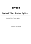
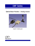
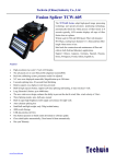
1
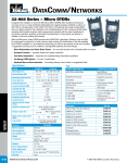
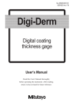
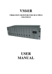
Thermal Stripper, TSAB-40
User Manual
User Manual Version 1.4
Table of Contents
Introduction _________________________________ 4 Safety Considerations ________________________ 5 Components ________________________________ 6 External Overview ____________________________ 7 Fiber Holder Platform Installation _______________ 8 Operation __________________________________ 12 Strip Length Adjustment _____________________ 15 Time & Temperature Adjustment_______________ 16 Fiber Size/Blade Adjustment __________________ 19 Cleaning ___________________________________ 22 Contacting Technical Support _________________ 24 COPYRIGHT NOTICE
©2007 3SAE Technologies Inc. All rights reserved.
Reproduction of this manual in any form requires
written permission from 3SAE Technologies, Inc.
Introduction
Introduction
The Jonard TSAB-40 Thermal Stripper is a fiber
preparation unit designed to thermo-mechanically
remove coatings from optical fibers.
It is designed to support from 40µm to 1000µm glass
optical fibers.
This manual is intended to instruct the user in the routine
use, adjustment, and maintenance of the Thermal
Stripper.
NOTICE: It is the responsibility of the user to use this
product for its intended purpose and according to this
manual. Jonard Industries cannot be responsible for
damages or injury resulting from failure to follow these
instructions.
4
Safety Considerations
Safety Considerations
•
•
•
•
•
•
•
•
•
•
The use of safety glasses is recommended.
Fragments of fiber can cause injury if they come into
contact with eyes.
Observe all safety precautions common to the
handling of optical fibers and dispose of fiber scraps
safely.
Do not operate the Thermal Stripper in the vicinity of
flammable vapors or liquids. Operation of the unit in
such an environment may increase the risk of fire or
explosion.
Before storing, the Thermal Stripper should be
turned off and the heating element cooled to room
temperature. This should also be done before
cleaning with compressed gas or canned air. These
products can contain flammable materials or
contaminants that may ignite.
Use only the A/C adapter that is supplied with the
Thermal Stripper. Using an improper power supply
may permanently damage the Thermal Stripper.
Do not modify or disassemble the Thermal Stripper
or any of its accessories, including the power
supply.
The heating element operates at temperatures up to
200° C. Never place your fingers inside the lid or
touch the heating element surface, as burns may
result.
The sides and bottom of the unit may become warm
to the touch after prolonged use.
Turn the Thermal Stripper off when not in use.
Do not expose any portion of the Thermal Stripper
to water or other liquids.
5
External Overview
Components
The standard Thermal Stripper kit contains the following
items:
• Thermal Stripper unit
• A/C Power Supply and Cord
• Cleaning Brush
• User Manual
• Fiber Holder Platform (purchase separately)
A/C Power Supply & Cord
Cleaning
Brush
Thermal Stripper
User
Manual
Fitel/Fujikura
Platform
Ericsson
Platform
Universal
Clamp
6
External Overview
External Overview
The following picture is an external overview of the
Thermal Stripper with Fiber Holder Platform installed.
Lid
Blade Adjustment
Thumbscrew
Heating Element
Stripping Blade
Fiber Holder
Platform
Cleaning Brush
7
Fiber Holder Platform Installation
Fiber Holder Platform Installation
A fiber holder platform or clamp is required for stripping
and is supplied separately. The platforms that are
available support Fitel/Fujikura or Ericsson fiber holders.
For operation without fiber holders a Universal Clamp is
also available.
For all three carriages the front of the carriage is to the left
in the following picture.
Fitel/Fujikura
Platform
Ericsson
Platform
Universal
Clamp
8
Fiber Holder Platform Installation
1. Remove the socket head screw with an M2.5 hex
head wrench.
Socket Head
Screw
2. At the end of the Thermal Stripper where you
removed the screw slide your fiber holder platform
or Universal Clamp onto the rail until it is completely
on.
Slide Rail
Fiber Holder Platform or
Universal Clamp Platform
9
Fiber Holder Platform Installation
3. Reinstall the socket head screw with an M2.5 hex
head wrench until tight.
Socket Head
Screw
4. Depending upon the platform you have just installed
and required strip length the cam needs to be
moved to adjust for the correct strip length (The cam
is installed in the position for the Fitel/Fujikura
platform from the factory).
10
Fiber Holder Platform Installation
Cam
Set Screw
Ericsson 5mm Strip /
Universal Clamp
Ericsson 17mm Strip
Fitel/Fujikura
5. Remove the set screw with an M1.5 hex head
wrench and then remove the cam.
6. Insert the cam into the correct position and secure in
place by installing and tightening the set screw with
an M1.5 hex head wrench.
11
Operation
Operation
To turn the unit on simply plug the power cord into the
outlet. Unplug the unit to turn it off. To operate the unit
1. Attach the power cord to the power supply.
2. Connect the power supply to the Thermal Stripper.
3. Plug the AC power cord into a 100-240 VAC (50/60
Hz) outlet.
4. The indicator L.E.D. displays a steady red while the
unit is heating to the set temperature. After the
operating temperature is reached the LED blinks
red. The unit is now ready for use.
5. Slide the fiber holder platform all the way to the left
(toward the stripping blades and heat element).
6. Place the fiber to be stripped in the fiber holder or
universal clamp such that the fiber extends to the far
edge of the heater.
7. Place the fiber holder on the platform and align the
fiber so that it is on the heating element and
between the “v” of the blades.
12
Operation
8. Close the blades by pressing down on the lid. The
LED will turn yellow for the duration of the “Wait
Time.” Continue to hold the lid closed until the LED
turns green. The green light indicates the fiber is
ready to be stripped.
Indicator LED
LED Color
Red
‘Blinking’ Red
Off
Yellow
Green
Meaning
Heating to “Set Point” temperature
Maintaining “Set Point” temperature
Heater at “Set Point” temperature
“Wait Time” to soften fiber coating
Ready to strip fiber
13
Operation
9. Continue to hold the blades closed and slide the
fiber holder and platform away from the heating
element.
10. Release the lid and remove the fiber holder. The
fiber is now ready to be cleaned, cleaved and
spliced.
14
Strip Length Adjustment
Strip Length Adjustment
1. For fine adjustment of the strip length, loosen the
set screw, shown below, with an M1.5 hex head
wrench. Rotate the cam to change the strip length.
Secure the cam by tightening the set screw with an
M1.5 hex head wrench.
Cam
Set Screw
15
Time & Temperature Adjustment
Time & Temperature Adjustment
For some coating types you may need to adjust the
Temperature and Time settings to insure the proper
stripping of fiber.
“Wait Time”
Adjustment
dial
“Set Point”
Temperature
Adjustment Dial
1. To adjust the “Set Point” temperature, use a small flat
screwdriver to rotate the temperature adjustment dial to
the appropriate setting (See table on next page or the
table on the back of the Thermal Stripper for setting
values).
16
Time & Temperature Adjustment
Value
0
Wait Time (s)
0
Set Point Temp (°C)
Off
1
2
60
2
4
70
3
6
80
4
8
90
5
10
100
6
12
110
7
14
120
8
16
130
9
18
140
A
20
150
B
22
160
C
24
170
D
26
180
E
28
190
F
30
200
17
Time & Temperature Adjustment
2. Factory default is 140°C for 250µm coatings.
Increase the time if stripping process is not smooth
and the fiber does not strip cleanly. Reduce the
temperature if melting of the coating is observed.
3. To adjust the “Wait Time”, use a small flat
screwdriver to rotate the time adjustment dial to the
appropriate setting (See table above or the table on
the back of the Thermal Stripper for setting values).
4. Increase the time if stripping process is not smooth
and the fiber does not strip cleanly. The following
table is a good starting point for different fiber
coatings.
Fiber Diameter
(µm)
125 (250 coating)
125 (900 coating)
200
Time Setting
3
5
6
Temperature
Setting
9
9
9
400
8
9
500
8
B
600
A
B
800
A
C
1000
B
D
18
Fiber Size/Blade Adjustment
Fiber Size/Blade Adjustment
For different cladding diameters it is necessary to adjust
the blade setting to optimize stripping performance. To
adjust the blade:
1.
Loosen the thumb set screw (counterclockwise) to
release the blade adjustment screw as seen below.
Thumb Set
Screw
Blade Adjustment
Thumbscrew
2. Turn the blade adjustment screw (clockwise) all the
way.
3. Follow the steps from the Operation section to load
the fiber.
19
Fiber Size/Blade Adjustment
4. Close the blades by pressing down on the lid.
7. Turn the blade adjustment screw (counterclockwise)
until the blades contact the fiber enough for an initial
strip.
8. Attempt to strip the fiber. If the fiber is stripped
proceed to the next step. If not repeat the previous
step
20
Fiber Size/Blade Adjustment
9. Place the stripped portion of the fiber in the stripping
blade and tighten the blade adjustment screw until
the blade grabs the fiber cladding. Test this by
sliding the fiber back and forth.
10. This setting should allow the fiber to move through
the blade with slight friction caused by contact with
the blades.
11. Turn the adjustment screw (clockwise) slightly,
approximately 15 degrees.
12. Tighten the thumb set screw (clockwise) to lock the
blade setting. The Thermal Stripper is now ready for
use.
21
Cleaning
Cleaning
With use debris will build up behind the blade as well as on
the heating element of the Thermal Stripper, affecting the
strength of the stripped fiber. While the Thermal Stripper
can be used many dozens of strips between cleaning, for
optimal performance we recommend cleaning after every
strip.
1. With the included cleaning brush, sweep excess
coating out from behind the stripping blade.
22
Cleaning
2. After excess coating is removed from behind the
blade thoroughly clean the heating element and
upper pad by brushing debris away from the
stripping blade toward the back of the Thermal
Stripper.
Upper Pad
Heating Element
23
Contacting Technical Support
Contacting Technical Support
Please refer below to contact 3SAE Technologies, Inc. with
questions regarding your Thermal Stripper. Please have
the model and serial number available.
Email:
[email protected]
Website:
www.3SAE.com
Technical Support Lines:
Monday - Friday, 8:00 AM to 5:00 PM CST
615-778-8812 Extension 2
After Normal Business Hours
800-864-1404
24