1
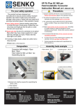
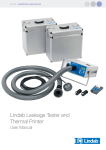
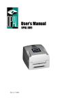
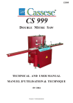
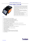
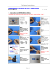
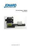
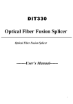
FO Field RM-FAC-08
01.07.2014 / V1.0 / Dei
–
–
–
–
–
–
–
–
Reduced back reflection ≥ 60dB
Easy to use, no training required
Multi-position diamond blade > 10’000 cleaves (10x1’000)
Angled cleaving of 125µm fiber
Average end angle of 8 degrees (+/- 1 degrees)
Mirror smooth end faces , no hackle
Minimal glass roll-off
Easy to use with "stapler" action
Specifications
Fiber diameter
125µm fiber
Cleave and angle
Preset cleave length
8° average
1° standard deviation
> 10mm for 250µm – 900µm
Blade life
>10’000 cleaves (10 positions with min. 1’000 cleaves)
Dimension
78 x 62 x 48mm
Weight
220g
Angle variation over core
1° (1-sigma)
Glass roll-off
≤ 40µm
Content
Specifications .............................................................................................................. 1
Issue & Scope ............................................................................................................. 2
Introduction ................................................................................................................. 2
Contents of Cleaving Kit & Unpacking ........................................................................ 2
Using the Cleaver ....................................................................................................... 2
Description of RM-FAC-08 Cleaver ............................................................................. 4
This document was prepared with the greatest possible care and
reflects the current state of technology at the time of printing.
Subject to corrections and technical changes.
Issue & Scope
This datasheet will be updated from time-to-time to reflect
technical changes to the product. It covers the basic
information’s of the RM-FAC-08 (FAC=Field Angled
Cleaver) precision optical fiber cleaver. More detailed
information’s can be found in the user manual delivered
with the product.
Introduction
The RM-FAC-08 Field Angled Cleaver is designed to
cleave a single 125µm diameter single mode optical fiber
with a mirror-smooth, damage-free end with the core
angled at 8º (±1º) from the perpendicular.
Cleaving a single mode fiber at around 8º from the
perpendicular ensures the back-reflection will not be guided
down the fiber, and hence the return loss will be around
60dB (reflectance of -60dB or greater).
8° angled cleaves are used in mechanical splices to form a
mechanical join for instance in FTTx applications.
The cleaver can be used as a field tool or on the bench top.
The fiber is fixed in to a fiber holder. The stripped fiber
passes between two dowels on the offcut side.
The cleave is carried out by pressing down the anvil. The
two vertical O-rings trap and clamp the fiber, the anvil
deflects the fiber to a stop and the tensioned fiber is
lowered on to the diamond blade to cleave the fiber.
The offcut is left between the dowels. Remove the offcut
and dispose of carefully
Contents of Cleaving Kit & Unpacking
The cleaver is supplied along with the following items:
1. User Manual: folded sheet
2. Fiber adapter for 900µm coated fiber (fitted to cleaver)
3. Fiber adapter for 2.1mm cabled fiber
4. Fiber adapter for 3.0mm cabled fiber
5. Carrying bag
Using the Cleaver
1. Fiber Preparation
Place fiber in fiber holder. Strip back primary, secondary
and outer coatings, as required. Clean fiber thoroughly
using a lint-free wipe wetted with alcohol (IPA)
The bare fiber should be at least 35 mm long to ensure that
the glass cladding passes over the hole in the reference
plane and through the dowels forming the fiber location
channel on the offcut side of the hole and over the edge of
the cleaving plane for easy offcut extraction.
Page: 2
www.rdm.com
2. Fiber insertion and setting cleave length
Insert fiber and align to the correct cleave length (minimum
= 10mm) and close the magnetic lids
- 900µm fiber adapter: pass coating between 2 pairs of
guidance posts and align end of coating (see below)
- 2.1mm or 3.0mm cable adapters: clamp cable in to
adapter with magnetic lid. 900µm coating passes between
2 pairs of guidance posts (see below)
Reichle & De-Massari AG
Binzstrasse 32
CHE – 8620 Wetzikon
Telephone HQ: +41 (0)44 933 81 11
Telefax HQ:
+41 (0)44 930 49 41
Tip:
Rotate the fiber tube so that the fiber curls downwards
towards the clamping planes.
Avoid upward curl because this makes the fiber difficult to
pass throught the dowel channels. Avoid sideways curl
because the fiber is not straight across the cleaving and
might miss the clamping ridges.
The stripped end of the fiber passes across the hole in the
clamping plane and through the pair of dowels on the offcut
side of the tool.
3. Cleaving the Fiber
The fiber is cleaved by pressing down the anvil.
The vertical O-rings trap and clamp the fiber.
The anvil deflects the fiber by a fixed amount
The cleaving plane, carrying the clamped and tensioned
fiber moves downwards so that the fiber strikes the
diamond blade, cleaving the fiber.
After cleaving, release the anvil and open the tool
4. Remove Cleaved Fiber
Remove the cleaved fiber by opening the magnetic lid
Take care that the cleaved fiber end does not touch the tool
surface as this may cause dirt to attach to the cleaved end
face.
5. Remove Fiber Off-Cut
The offcut is left between the dowels after cleaving.
Remove the offcut and dispose of carefully.
Please Note: The cleaver may not work properly if the
offcut from previous cleaves remains in the tool
The fiber off-cut is a sharp hazard. Dispose of safely. The
tool is ready to cleave the next fiber.
6. Cleaving Problems
Offcut fiber in channel. Remove with finger or by turning
tool on side and shaking out. Dispose of offcut
Offcut fiber in other part of tool. Remove using wipe or
finger. Dispose of offcut
Will not cleave. Blade damaged - advance blade by turning
end screw clockwise by 1 full turn.
Measuring End Angle: It is not possible to measure the
end angle from a side projection (e.g. in a fusion splicer).
The angle can be measured from the cleaved surface using
surface profiler or interference technique.
Blade damage: A large chip is seen in the cleaved end
face. advance blade by turning end screw clockwise by 1
full turn.
Excess hackle or poor surface quality: cleave is usable if
core of fiber end face is smooth.
High back-reflection: Cleaver and/or fiber are dirty. With dirt
back-reflection is increasing. Thoroughly clean tool.
This document was prepared with the greatest possible care and
reflects the current state of technology at the time of printing.
Subject to corrections and technical changes.
Description of RM-FAC-08 Cleaver
Fiber/tube holder
Clamping-plane
Fiber positioner
Anvil
O-rings
Diamond blade
Blade advance screw
Page: 4
www.rdm.com
Reichle & De-Massari AG
Binzstrasse 32
CHE – 8620 Wetzikon
Telephone HQ: +41 (0)44 933 81 11
Telefax HQ:
+41 (0)44 930 49 41