1
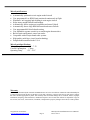
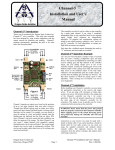
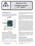
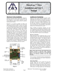
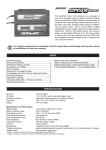
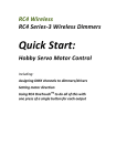
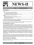
MicroSynch TM Installation and User’s Manual OSA MicroSynch™ Thank you for purchasing the Oregon Scale Aviation Inc. MicroSynch engine synchronizer system. MicroSynch allows the model aviation enthusiast to achieve the ultimate in realism, performance and functionality, while providing an unprecedented level of safety in the operation of multi-engine model aircraft. This controller has been designed by R/C aviation enthusiasts with the utmost concern for reliability, safety and usability. Ground Blk/Brn +5V Red/Red Signal Yel/Or Receiver Input adverse yaw induced by unequal thrust. In addition, MicroSynch monitors and continuously adjusts the engines for synchronization. If one engine unexpectedly stops or significantly reduces RPM, MicroSynch reduces the throttle of the functional engine automatically to avoid a hazardous and often aircraft-fatal snap spin. The pilot can regain throttle control by lowering the throttle stick below a programmable “Failsafe Threshold”. The high and low throttle sensitivity is fully adjustable, allowing optimum synchronization response time while avoiding “tail-wagging” oscillations. These adjustments allow the user to tune MicroSynch to match the engine throttle response characteristics. MicroSynch also allows the user to program a minimum RPM for the engines. While synchronizing, the engine RPM is constantly monitored, and if it drops below the user programmable limit, the throttles will be automatically increased. This revolutionary OSA exclusive feature helps avoid losing an engine on final approach or during prolonged periods of idling. LED Left Throt Servo Out Right Throt Servo Out High Speed Response Rate Reverse Input Rev Left Servo Rev Right Servo EEPROM Low Speed Response Rate Left RPM Sensor In Right RPM Sensor In Signal Yel/Or +5V Red/Red Ground Blk/Brn MicroSynch eliminates two of the largest risks to multi-engine model aircraft operation; differential thrust induced yaw and engine failure induced loss of control. The most common non-pilot induced reason for the loss of twin engine model aircraft is the failure of an engine under high throttle conditions (typically take-offs or aborted landing attempts) and during the prolonged low throttle condition experienced in the landing approach. If the model is operated while several other aircraft are in the air or running in the pit area, the pilot may not even be aware of the failure until the aircraft has already entered a catastrophic flat spin or snap roll. In the event of an engine failure, MicroSynch will quickly respond to the failure by throttling back the good engine to a manageable throttle setting (pre-programmed into the controller during installation). Throttling back automatically insures the pilot can maintain reasonably straight and level flight until regaining control of the remaining engine by reducing the throttle stick to a position below the failsafe threshold. The pilot can then carefully bring the aircraft “home” with full control over the remaining engine, knowing that significant rudder control will be necessary to control the yaw induced by single engine operation. MicroSynch is easy to install and adjust. The MicroSynch controller LED provides feedback under both programming and operational conditions simplifying installation and operation. Once adjusted to your particular aircraft and engine requirements, further adjustment is not necessary. All adjustments are stored in the non-volatile memory, so no special stick movements or programming is required prior to each flight. Once it is setup, it is truly a “start it and fly it” system. Figure 1 MicroSynch Introduction MicroSynch was designed to synchronize or match the RPM of internal combustion engines or electric motors on twin engine model aircraft. Maintaining matched RPM will allow the aircraft to avoid Oregon Scale Aviation Inc. www.oregonscaleaviation.com Page 1 MicroSynch Installation and User’s Manual Doc # 107113 MicroSynch Installation Before installing MicroSynch, it is recommended that you complete the “normal” installation of the throttle servos and radio in your aircraft. Try to use near 100% throws to minimize mechanical slop and to better match the programming of the MicroSynch. You should complete all full throttle and idle adjustments (both mechanical and transmitter adjustments), and as a safety measure, insure that you can stop both engines by reducing the throttle stick and throttle trim tab to their lowest positions. It is important to insure the engines are running at roughly the same RPM when idling. This can be measured with a non-contact model airplane tachometer. Once you have completed the “normal” aircraft radio and servo installation and throttle adjustments, you can then proceed with the MicroSynch installation. Connect the receiver throttle output to the MicroSynch input as shown in Figure 2. This requires a female to female connector for your radio system. If you cannot purchase a female to female connector, you can build one using an aileron extender and the supplied connector. Please refer to the “Connector Installation” section at the end of this document for details. Always insure correct polarity as shown in Figure 1. Please insure that the power and ground leads are properly connected to MicroSynch before applying power to the system. Reversing power and ground may damage the MicroSynch controller and void the warranty. Installing the Magnets, LED and RPM Sensors The first step in the MicroSynch installation is to become familiar with the RPM sensor sensing distance and magnet polarity requirements. To help with this, a mode has been built into the controller that causes the LED to turn on or off when it senses a magnetic field. To enter this mode, turn the controller off and move all of the switches to the “On” position. Plug in only one RPM sensor insuring the sensor is plugged into the correct side of the controller. Turn on the receiver and controller. Move one of the supplied magnets in front of the sensor and observe the LED. As you move the magnet across the sensor, the controller will blink the LED if it senses the magnet. You can explore using this mode to find the most sensitive face of the sensor and the most sensitive orientation of the magnet. Find the orientation that allows sensing the magnetic field at the furthest distance from the RPM sensor and make a note of this distance. You will need this information during the sensor installation. Mark the magnet and the sensor as a pair so that you can later install them in the correct orientation. If you plan to use two magnets for each engine, mark both magnets. Now repeat the procedure for the other sensor and magnet(s) pair. When finished, power down the MicroSynch controller and return all switches to the “Off” position. Be sure to keep the magnet and sensors together as the most sensitive face may vary from sensor to sensor. Drill a small hole (or holes if using two magnets) in the engine hub or spinner backing plate that is the same diameter as the magnet. The use of aluminum spinner back plates is highly recommended as it reduces the chance of a magnet vibrating loose. Try to place this hole in an area that allows you to easily mount the RPM sensor in close proximity. The magnet should rotate past the center of the sensor if possible. If using two magnets, the holes must be at the same distance from the center of the spinner plate, and must be separated by 180 degrees. After thoroughly cleaning the hole(s) and the magnet(s), fix the magnet(s) in the hole(s) using JB Weld or an appropriate adhesive and allow it to cure overnight. This must be an extremely reliable joint. If a magnet falls out during flight, the system will enter Failsafe mode and reduce both throttles to the Failsafe setting. Oregon Scale Aviation Inc. www.oregonscaleaviation.com Page 2 Next mount the RPM sensors to the engine mounting bolts or any other convenient location such that the end of the RPM sensor is approximately ½ of the farthest sensing distance you identified in the previous step. If in doubt, mount the RPM sensor 1/16- 3/32 inch away from the magnet when the magnet is rotated to a position in line with the sensor. The use of carbon fiber tubes to support the sensor has proven very effective. Again, you can use JB Weld or any other reliable method to insure these sensors do not vibrate loose during flight. It is best to mount the sensors to the engine so that when the engine moves or vibrates, the sensors move with it. Route the RPM sensor cables through the wings and into the compartment where the MicroSynch controller will be mounted. In general, this is in the center section of the wing as this location minimizes the number of leads that must be disconnected when removing the wings from the fuselage. Avoid routing the sensor cables parallel to the receiver antenna where possible. Do not plug the RPM sensors into the MicroSynch at this time. Mount the LED in a location of your choice insuring that it is visible during engine start-up and operation while the aircraft is in the “pit”. Some pilots prefer to mount the LED in the cockpit so that it is visible through the clear canopy, yet is somewhat shaded in direct sunlight. Plug the LED into the MicroSynch controller referring to Fig. 1. Configuring the Input Signal and Servo Reversing Insure the throttle output of the Receiver is connected to the MicroSynch controller unit (see Figs 1 and 2). Again, be sure to observe correct polarity (ground is always towards the outside edge of the controller circuit board). The receiver and the LED should be the only connections to the controller at this time. Connect both throttle servos insuring the right servo is connected to the Right Throttle Servo Output as shown in Fig 1. Configuring the input signal direction and servo reversing will normally only need to be performed once. However, it must be repeated if you later decide to reverse the throttle servo throw from the transmitter. With the MicroSynch controller and receiver turned off, move Switch 3 and Switch 4 to the “On” position. These switches are labeled as EEPROM and Rev Right Servo in Figure 1. Moving switches 3 and 4 to the “On” position forces MicroSynch to enter “Input and Servo Reversing Setup Mode” when it is powered up. Turn MicroSynch on by switching on the receiver. Turn on the transmitter and move the transmitter throttle stick to the idle position. Wait about 15 seconds for DSM/DSS systems to “Link-Up”. The MicroSynch LED will flash if the input is correctly configured. If the LED is not flashing after waiting 15 seconds, move Switch 1 (Reverse Input) to the “On” position. The LED should now flash. If it does not, turn off the Receiver and MicroSynch and check all connections for proper polarity and insure your receiver and transmitter batteries are charged. You may have to adjust throttle throw on the transmitter if you cannot otherwise get the LED to blink. Repeat the above sequence until you see the blinking LED. Next, move the throttle stick to full throttle and verify that both throttle servos travel in the correct direction (the LED will stop blinking when you move the throttle to full). If the servos do not move in the correct direction, use the Right and Left Servo Reversing switches to obtain the correct direction of travel. Once the servos travel in the correct direction in response to stick movement and the LED flashes when the stick is at idle, move the EEPROM switch (Switch 4) to the “Off” position. You have now completed configuring the input signal and output servo reversing! MicroSynch Installation and User’s Manual Doc # 107113 Turn the receiver and transmitter off and move all switches to the “Off” position. Setting the Throttle Travel With all of the MicroSynch switches turned off, turn on the receiver and the transmitter. Verify that the throttle servos travel in the correct directions as you move the throttle stick on the transmitter. Now that the servos are traveling in the correct directions, adjust the transmitter settings to achieve full throttle throw and correct idle position just as you would for any standard radio/engine installation. The carburetor barrels should rotate to a full open position without binding and without stalling the throttle servos. The barrels should also fully close without binding or stalling the servos. When the throttle stick and throttle trim tab is completely lowered, the barrels should move to a position that guarantees the engines will stop. With the RPM sensors disconnected, restrain the aircraft and start both engines. You should be able to establish a reliable idle with the throttle stick in the fully lowered position by adjusting the trim tab. Once satisfied with the servo travel, and completing adjustments to insure that the engines run at roughly the same RPM at idle, stop the engines and turn the receiver and transmitter off. RPM Sensor Dynamic Test Mode MicroSynch includes a feature that allows you to test the magnet and RPM sensor installations while the engines are running. When placed in “RPM Sensor Dynamic Test Mode”, the controller will flash the LED when it senses an RPM signal from either sensor within the 2000 – 5000 RPM range or in the 8,000 - 12,000 rpm range. If you are using 2 magnets per engine, it will flash the LED when the RPM signal is in the 1000 - 2500 RPM or 4000 – 6000 range. If no signal is sensed, the LED will remain off. Since most model aircraft engines idle in the lower range, you can simply and quickly determine if your magnets and RPM sensors are functioning properly. The upper range is useful in determining if the sensors are too far away from the magnet or if aircraft induced vibrations are causing a sensing failure. Using this feature in conjunction with a tachometer will insure a reliable sensor installation. To enter the Sensor Dynamic Test mode, turn off the MicroSynch and connect the RPM sensors to the MicroSynch controller unit. Note that the left RPM sensor must be plugged into the Left RPM Sensor input of the controller unit (see Fig 1). Verify that the grounds (black or brown wires) are towards the outer edges of the boards (See Fig. 1). Also insure the throttle servos are connected to the Microsynch controller. Move Switches 2, 3 and 4 (Rev Left, Rev Right and EEPROM) to the “On” position. Leave Switch 1 in the “Off” position. This will force MicroSynch to enter the “RPM Sensor Dynamic Test Mode” the next time it is powered-up. Turn on the receiver and the transmitter. The LED should not be flashing. Verify that the throttle servos travel in the correct directions as you increase and decrease the throttle stick position before moving to the next step. To test your Magnet/RPM sensor installation, start one of the engines and let it idle in the 2000 to 5000 RPM range (1000 – 2500 RPM for dual magnet installations). The LED will flash if it receives a valid signal. If it does not, you may need to adjust the position of the RPM sensor, or check the polarities of the RPM Sensor connection to the controller. Advance the throttle to achieve 8,000-12,000 RPM (4000 – 6000 PRM for dual magnet installations) and verify the LED blinks in that range as well. The LED shold not blink when outside of these RPM ranges. Once you are satisfied that the controller is receiving a Oregon Scale Aviation Inc. www.oregonscaleaviation.com Page 3 valid signal, stop the engine. The LED will stop flashing. Now start the other engine and verify it is receiving a valid signal in the two RPM ranges. Once satisfied that both sensors are operating properly, stop the engines, power down the receiver and return all switches to the “Off” position. Programming StopSynch and Failsafe Positions Next you will complete the programming of the StopSynch and Failsafe setpoints. This programming is a one-time set-up step and will not normally need to be repeated. These two adjustments must be performed as a group. This section assumes the receiver throttle output is connected to the MicroSynch input and that the LED is connected. Disconnect the RPM sensors for this step. With the receiver turned off, move the “EEPROM” switch (Switch 4) to the “On” position and all other switches to the “Off” position. Now turn on the transmitter and receiver. After a short delay, the LED should flash once and then pause. It will repeat this single flash sequence until you have programmed the StopSynch position. StopSynch is the transmitter stick position at which synchronization stops. Any Tx stick setting below this point will cause both throttles to move to the position commanded by the Tx stick. This insures that you can reliably turn the engines off from the transmitter. In general, set this position to slightly below the reliable idle position if you plan to use the Low RPM Monitor feature, or slightly above a reliable idle position if you do not plan to use the low RPM monitoring feature. Restrain the aircraft and start both engines. Adjust the Tx stick position to the desired StopSynch point. Once satisfied with the StopSynch Tx stick position, move the EEPROM switch to the “Off” position. This completes programming of the StopSynch position, but do not turn off the receiver or stop the engines until you have programmed the failsafe setpoint. Move the EEPROM switch to the “On” position. The LED should repeat a 2-Flash sequence, telling you it is ready for the Failsafe throttle position. Move you throttle stick to the Failsafe position. This position should be a low power setting that is very reliable but not so fast that it would cause severe yaw in a one-engine running condition. If one engine fails, this is the throttle position that the other engine will be set to. Once the throttle stick is in the desired Failsafe position, move the EEPROM switch to the “Off” position. The LED will turn off. You have successfully completed programming of the throttle setpoints. Stop the engines and turn off the transmitter and receiver. Return all MicroSynch switches to the “Off” position. Setting the Low RPM Limit An exciting new feature has been added to MicroSynch that enables it to monitor and adjust the RPM of the engines to insure they do not fall below a user defined minimum RPM while synchronizing (it will ignore this setpoint once the Tx stick is moved below the StopSynch point). This feature is enabled by moving Switch 1 to the on position, but before you enable this feature, you must set the minimum desired RPM. It is recommended that you set this slightly above a reliable idle. While MicroSynch monitors the RPM, it will not adjust until the RPM is below the minimum RPM setpoint, and even then, the response is not instantaneous. Setting the Low RPM Limit a few hundred RPM above the lowest reliable idle will insure the RPM never drops below the reliable limit. Insure the MicroSynch power is off, and move Switches 1,3 and 4 to the “On” position. Leave Switch 2 in the “Off” position. Turn on the controller and notice that the LED is flashing. Insure the throttles move in the correct direction as you move the transmitter throttle stick. Start both engines and adjust them until you have achieved a reliable long term idle. Move the trim up a click or two from here if you want to insure a margin of safety. Once satisfied MicroSynch Installation and User’s Manual Doc # 107113 with the Low RPM setting, move Switch 4 to the “Off” position. Stop both engines and turn off the Rx/Microsynch. Return all MicroSynch switches to the “Off” position. Adjusting the Synchronizer Response Rates: Not all engines respond in the same way to a change in throttle position. For example, large 4-stroke engines may respond more slowly to throttle changes than small 2-stroke engines. As a result, MicroSynch may need to drive smaller changes to the 2-stroke installation than to the larger 4-stroke installation. The Response Rate pots (See Fig 1) are used to tune MicroSynch to specific engine and servo combinations. The objective of these adjustments is to set the Response Rate as high as possible without causing throttle oscillation or “hunting”. The easiest way to complete these final adjustments is to properly restrain the aircraft so that it can run it at full throttle handsfree. This will allow you to experiment with the adjustments safely. Insure both servos, the RPM sensors, the LED and throttle input are properly connected. Center both the low speed and high speed response rate pots. With all MicroSynch switches in the off position, turn on the transmitter and receiver and insure the throttles travel in the correct direction when you move the Tx throttle stick. Start both engines, and after a brief warm-up, move the transmitter throttle stick to about 75% throttle. Wait until both engines have synchronized and the LED is blinking rapidly or is on solid (indicating that MicroSynch is synchronizing). Turn the High Speed Response Rate pot full clockwise and move the Tx Throttle stick a little in either direction. Notice that the engines may oscillate in and out of synchronization as it overcorrects the throttle. If this occurs, reduce the High Speed Response Rate pot until the oscillation stops. Move the throttle to about 80%. If the system takes a long time to resynchronize, and does not hunt, increase the High Speed response rate by turning the pot clockwise about 1/8 of a turn and try again. If on the other hand, the system oscillates or hunts significantly, reduce the sensitivity by turning the High Speed Response Rate pot counter-clockwise a little. Next, move the throttle stick to about 1/4 throttle (but above the Stop Synch Point) and adjust the Low Speed Response Rate pot until the engines synchronize quickly in the low range yet do not hunt or oscillate. Now observe how the engines respond to changes in throttle stick position. Set the throttle at about 1/3 and let the system stabilize. Move the throttle to 2/3 position quickly. If the engines hunt or oscillate excessively, reduce the high speed response rate pot. If they are very slow to synchronize, increase the high speed response rate slightly. Repeat this adjustment for the low speed response rate by moving the stick from full throttle down to about ¼ throttle. Once you have adjusted the response rates to limit hunting throughout the throttle range, the response rate adjustment is complete. The LED blinks in response to how closely the engines are synchronized. If the RPMs match, the LED will stay lit. If the RPMs are different by 220 RPM or less, but not matching, the LED blinks rapidly. The slower the LED blinks, the less synchronized the engines are. For most aircraft, the LED will not stay on solid all the time, but will switch between being on all the time to rapidly blinking. Once you have completed tuning on the ground, it is best to verify proper operation in flight. Oscillation inflight is very easy to detect by the sound of the engines or by observing that the tail of the aircraft “wags” in response to throttle changes. If this occurs, reduce the sensitivity slightly and try again. Once these settings are finalized, further adjustment is unnecessary. MicroSynch Operation and Recommendations: Once programmed, MicroSynch is remarkably easy to use. Simply power-up the transmitter and receiver. Start an engine and perform the normal needle valve adjustments at full throttle and idle to insure proper mixture. Stop that engine and repeat the procedure on the second engine (this is not required for proper MicroSynch operation, Oregon Scale Aviation Inc. www.oregonscaleaviation.com Page 4 but is generally considered good multi-engine technique). Refuel and then start both engines in any order. Microsynch will not start synchronizing until both engines are started and the throttle has been moved past half throttle. Once synchronization has started, it will synchronize at all throttle positions above the StopSynch point. Verify that MicroSynch is synchronizing by observing that the LED is either on or flashing. The faster the LED is blinking, the more closely synchronized the engines are. When the engine RPMs match exactly, the LED will stay on. It is normal for the engines to move slightly in and out of synchronization while running. If you want to use the Low RPM Limit feature, make sure Switch 1 is in the “On” position. You are now ready to fly! On take-off, if at all possible, run the engines up slightly past the StopSynch point, but not enough to start the aircraft rolling. This will allow the engines to synchronize before starting the take-off roll, insuring a straight and predictable take-off. On the take-off roll, advance the throttle quickly past the region where one engine may enter 2 cycle operation and the other remains in 4 cycle mode. It is very difficult to synchronize 2 stroke engines through this transition region. Once in flight, enjoy the beautiful sound of synchronized engines, and notice that the airplane tracks exceptionally straight and true. In the unfortunate event of the loss of an engine during flight, or if one engine is running at least 2400 RPM slower or faster than the other engine for at least 2 seconds, MicroSynch will automatically throttle back to the Failsafe setting. The throttles will remain at this setting until the pilot lowers the throttle stick below the Failsafe setting. From this point onward, the pilot has full control over the throttles, but would obviously desire to avoid high throttle conditions that might induce a flat spin or snap-roll. If failsafe was entered because the RPM differential between the engines exceeded 2400 RPM for more than 2 seconds, re-synchronization can occur in-flight by reducing the throttle below the failsafe point and then advancing it to past half throttle. System Connection Diagram Receiver LED Left Throttle Servo Right Throttle Servo Left RPM Sensor Right RPM Sensor Figure 2 Connector Installation: Before installing your MicroSynch controller, you must insure that you can make the appropriate connections to your servos and receiver. If you are using a JR, Airtronics or Futaba radio system, the servos will connect directly to the servo output pins of the MicroSynch controller unit (see Figure 1 for correct polarity). Always insure that ground connections are on the outer edge of the controller as outlined in Figure MicroSynch Installation and User’s Manual Doc # 107113 1. Connections to the receiver for these systems can be easily made with standard aileron extenders and the supplied connector. Retention Slots Note that MicroSynch uses keyed RPM sensor connectors, and you are provided with a dedicated right and left RPM sensor. While plugging them into the wrong connector will not damage them, they will not function properly until correctly installed. Retention Finger Crimp Wire Figure 3. If you need to connect to the receiver using the supplied connector, simply strip the servo or receiver wire back approximately 1/8” and crimp the wire into the pin supplied using a crimping tool or needle nosed pliers. Be sure the wire is firmly crimped in place, and insert all 3 leads into the supplied housing until the retention fingers snap into the housing slot (see Figure 3). Test your installation by gently pulling on the leads to insure they are firmly seated. Oregon Scale Aviation Inc. www.oregonscaleaviation.com Page 5 MicroSynch Installation and User’s Manual Doc # 107113 MicroSynch Features Automatically synchronizes twin engine model aircraft User programmed Low RPM Limit monitored continuously in flight Eliminates “tail-wagging”and skidding in twin engine aircraft Helps insure straight takeoffs and landings Automatically detects engine-out conditions and enters Failsafe Automatically detects large RPM differential and enters Failsafe User programmable Failsafe throttle setting User adjustable response sensitivity to match engine characteristics Built-in static and dynamic sensor test modes Compatible with all major brand radio systems High quality multi-layer circuit board technology Designed and assembled in the U.S.A. MicroSynch Specifications Voltage Range 4.5V – 7.2V Current Consumption < 30ma Operating Temp. 0C - 70C Warranty OSA warrants the MicroSynch controller and RPM Sensors to be free from defects in materials and workmanship for a period of 90 days from the date of purchase. If your unit is defective, return to OSA and we will repair or replace the unit as deemed appropriate by OSA. This warranty does not include damage due to accidents, misuse, improper installation, tampering, radio interference, unauthorized repair or acts of God. OSA will not be responsible or pay for loss of time, loss of use, inconvenience, incidental, consequential or property damages due to the use of this product. Oregon Scale Aviation Inc. www.oregonscaleaviation.com Page 6 MicroSynch Installation and User’s Manual Doc # 107113