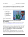
1
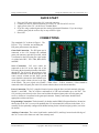
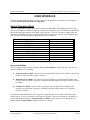
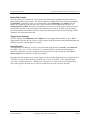
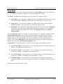
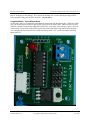
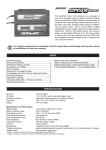
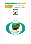
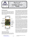
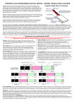
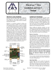
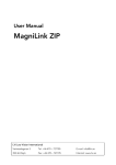
Cheap Control Systems Cheap Six Channel (C6C) Servo Controller Version 2.0 The Cheap Six Channel (C6C) Servo Controller is a low cost embedded controller that allows the Sony Playstation 2 (PS2) game pad (or equivalent) to control up to six standard R/C servos. It provides proportional, momentary or latched control of up to four servos via the game pad joysticks and bidirectional or uni-directional momentary control of up to two servos via the game pad trigger buttons. The C6C also provides dual-channel mixing for both the left and right game pad joysticks allowing them to be used with a pair of Electronic Speed Controls (ESC) to provide tank-style skid steering. The C6C supports both tethered and wireless game pads allowing it to be used as a short-range R/C controller (up to 90 feet depending on the wireless game pad used). The C6C is perfect for short-range control of R/C tanks, cars, boats, and robots. OVERVIEW Features ● Supports any PS2 game pad as input device – compact, ergonomic, inexpensive ● Controls up to six standard R/C servos or servo-compatible devices ● Joystick channels can be operated in either proportional, momentary or latched modes ● Trigger channels can be operated in momentary mode ● Dual-channel mixing mode for both left and right joysticks via jumpers ● Servo center, reverse and latch speed adjustment on all joystick channels ● All settings can be saved to EEPROM Power ● ● ● Flexible input power +6.0 VDC to +8.4 VDC Provides power to all servos, tethered game pad and wireless game pad receiver Analog light on tethered game pad indicates power on Compatibility ● Works with tethered and wireless game pads that support Analog mode ● Tested with a variety of game pads and servos, including: ○ Servos: Futaba (J connector), Hitec, Airtronics (blue connector) ○ Tethered Game Pads: Sony PSone Analog, Sony Dual-Shock 2 ○ Wireless Game Pads: dreamGEAR, Pelican Chameleon, MadCatz ○ Does not work with Logitech wireless game pads Revision 2008-04-13 Copyright 2008, Cheap Control Systems 1 of 15 Cheap Control Systems Cheap Six Channel (C6C) Servo Controller v2.0 QUICK START 1. 2. 3. 4. Plug your PS2 game pad into the C6C game pad connector Connect your servos, motor controllers, etc. to the C6C just like an R/C receiver Apply power to the C6C via the Power Terminal Block If you are using a tethered game pad, the Analog light should illuminate. If you are using a cordless game pad, the receiver may or may not have a light. 5. Have fun!! CONNECTIONS The completed C6C is shown in Figure 1. The PCB is 1.75 by 2.0 inches, not including the PS2 game pad connector (not shown). Game Pad Connection: The PS2 game pad is connected to the C6C through the standard game pad connecter and cable provided, which is connected to the PCB using the 6-pin header via solder holes BLU, YEL, GRA, BRO, RED, and BLK. Servo Connection: R/C servo cables are connected to the C6C on the right side of the PCB using the horizontal pin headers labeled S1 through S6. For all servos, the red power wires should be connected to the R (Red) pins in the center vertical column and the black ground wires should be connected to the B (Black) pins in the right vertical column (closest to the edge of the board). The servo signal wire (Futaba = White, Hitec = Yellow, Airtronics = Blue) should be connected to the S (Signal) pins in the left vertical column (closest to the microcontroller). Power Connection: The C6C is supplied electrical power using the blue, two-hole terminal with ports labeled V+ and GND . The C6C requires a minimum of +6 VDC and can handle up to +8.4 VDC. The C6C provides power directly to the servos and to either the tethered game pad or wireless game pad receiver, whichever is connected to the game pad connector. Battery connections should include appropriate switches and fuses. Programming Connection: The horizontal 5 pin header marked PROG (Program Interface) located on the top edge of the C6C is reserved for updating the C6C microcontroller's software in the future. It is currently used to optionally configure dual-channel mixing for the left and/or right joysticks (see below for details). Auxiliary Connection: The vertical 4 pin header marked AUX (Auxiliary) located on the left edge of the C6C is reserved for future use and is not currently used. Revision 2008-04-13 Copyright 2008, Cheap Control Systems 2 of 15 Cheap Control Systems Cheap Six Channel (C6C) Servo Controller v2.0 USER INTERFACE The PS2 game pad (either tethered or wireless) serves as the complete user interface for all operations, including Normal Operating Mode and Setup Mode. Normal Operating Mode The C6C is designed to provide servo control much like a standard R/C transmitter and receiver, with four (4) servo channels controlled by the two (2) game pad joysticks and two servo channels controlled by the left and right trigger buttons on the front of the game pad. The C6C also allows control of the four joystick servo channels using the two button pads located just above the joysticks on the PS2 game pad. The C6C maps the following game pad inputs to the 6 servo channels: PS2 Game Pad Input Associated Servo Channel Right Joystick – LEFT/RIGHT Channel S1 Right Joystick – UP/DOWN Channel S2 Left Joystick – LEFT/RIGHT Channel S3 Left Joystick – UP/DOWN Channel S4 Right Button Pad – SQUARE & CIRCLE Channel S1 Right Button Pad – TRIANGLE & CROSS Channel S2 Left Button Pad – LEFT & RIGHT Channel S3 Left Button Pad – UP & DOWN Channel S4 Left Trigger Buttons – L1 & L2 Channel S5 Right Trigger Buttons – R1 & R2 Channel S6 PS2 Input Mapping to Servo Channel Servo Control Mode The C6C provides support for three different Servo Control Modes on each of the four joystick servo channels (channels 1-4), including: ● Proportional Servo Mode – the servo moves proportionally whenever the joystick is moved and returns to center when the joystick is released. ● Momentary Servo Mode – the servo moves a full 45 degrees in either direction whenever the joystick is moved past the “trip point” in that direction and returns to the center when the joystick is released. ● Latched Servo Mode – the servo moves at a preset speed in either direction whenever the joystick is moved past the “trip point” in that direction and remains wherever it is when the joystick is released. In Momentary and Latched modes, the “trip point” is approximately 30% in either direction from the center position. The servo will not be moved until the joystick is moved at least that far. By default, all four joystick channels operate in Proportional Servo Mode. (In the next section we discuss how to change the Servo Control Mode and other related C6C settings.) Revision 2008-04-13 Copyright 2008, Cheap Control Systems 3 of 15 Cheap Control Systems Cheap Six Channel (C6C) Servo Controller v2.0 Button Pad Controls The four joystick servo channels (1-4) can also be operated using the eight buttons located on the two button pads just above the joysticks. The specific operation is determined by the current joystick Servo Control Mode. Specifically, if the servo control mode is either Momentary or Latched mode, the buttons will operate the servo the same way as if the joystick was moved passed the trip point. In Proportional Servo Mode, the buttons will cause the servo to move a full 45 degrees whenever they are pressed and return to the current joystick position when they are released. In other words, the buttons provide momentary servo behavior while the joystick provides proportional behavior, allowing a skilled operator to use either mode as needed. Trigger Servo Channels The C6C supports only Momentary Servo Mode for the two trigger button channels (5 & 6). When a trigger button is pressed, the servo moves a full 45 degrees in the direction associated with that button and returns to the center when the button is released. Servo Direction Throughout this User Manual, we refer to servo directions using the terms “forward” and “backward”, not “right”, “left”, “up”, “down”, “clockwise” or “counter-clockwise” because the actual physical direction in which the servo moves depends on the brand of servo being used and the current Servo Reverse Mode (discussed below) for that servo channel. By design, the C6C generates servo control signals in such a way that Futaba brand servos physicall move “clockwise” (when viewed from above) when the servo is moved “forward”, while Airtronics brand servos move “counter-clockwise”. When the servo direction is “reversed”, the servos will physically move in the opposite direction, but we still refer to that direction as the “forward” direction. Revision 2008-04-13 Copyright 2008, Cheap Control Systems 4 of 15 Cheap Control Systems Cheap Six Channel (C6C) Servo Controller v2.0 Setup Mode As described above, the C6C provides three different Servo Control Modes for the joystick channels (14). This section describes how to configure, save and restore the joystick settings. The “Select” and “Start” game pad buttons are used to control C6C settings as follows: ● Save Settings – press and hold the “Select” button until the GREEN led flashes twice to save the current C6C settings to EEPROM so that they are used whenever the C6C is powered on. ● Factory Reset – press and hold the “Select” and “Start” buttons at the same time until the GREEN led flashes twice to restore the C6C to the factory default settings. ● Setup Mode – press and hold the “Start” button until the RED led is ON to enter Setup Mode. The RED led will remain lit at all times during Setup Mode as a reminder. Press and hold the “Start” button again until the RED led is OFF to exit Setup Mode and return to Normal Operating Mode. While in Setup Mode, the four (4) joysticks are still used to control servo channels 1 through 4 just like in Normal Operating Mode. However, the two button pads and four trigger buttons are used to configure the C6C settings and will not operate the servo channels. This allows operators to make multiple changes to the joystick settings, while still allowing them to test those settings using the joysticks. After exiting Setup Mode, the button pads and trigger buttons will again operate the servo channels as described in the Normal Operating Mode section. In Setup Mode, the four trigger buttons are used to select the settings to be modified as follows: ● Servo Center Setup – press and release “L1” to change the center position of the joystick servo channels. The GREEN led will flash once (1). ● Servo Reverse Setup – press and release “L2” to change the servo direction on each of the joystick servo channels. The GREEN led will flash twice (2). ● Servo Control Setup – press and release “R1” to change the Servo Control Mode on each of the joystick servo channels. The GREEN led will flash three (3) times. ● Latch Speed Setup – press and release “R2” to change the servo speed when operating in Latched Servo Mode on each of the joystick servo channels. The GREEN led will flash four (4) times. We now describe each setup mode in detail. Revision 2008-04-13 Copyright 2008, Cheap Control Systems 5 of 15 Cheap Control Systems Cheap Six Channel (C6C) Servo Controller v2.0 Servo Center Setup The center position of each joystick servo channel can be moved by pressing the button pads as follows: PS2 Game Pad Input Right Button Pad Left Button Pad Button Channel Center Adjustment CIRCLE S1 Forward SQUARE S1 Backward TRIANGLE S2 Forward CROSS S2 Backward RIGHT S3 Forward LEFT S3 Backward UP S4 Forward DOWN S4 Backward Servo Center Setup Controls With the joystick centered, press and hold the appropriate button until the servo reaches the desired center position, then release the button. Note, the center position can only be moved 22.5 degrees in either direction from the factory default center position, which prevents most servos from hitting their hard limits if the center is moved too far one way or the other. Servo Reverse Setup The direction of each joystick servo channel can be changed by pressing the button pads as follows: PS2 Game Pad Input Right Button Pad Left Button Pad Left Joystick Right Joystick Button Channel Servo Direction CIRCLE S1 Normal SQUARE S1 Reverse TRIANGLE S2 Normal CROSS S2 Reverse RIGHT S3 Normal LEFT S3 Reverse UP S4 Normal DOWN S4 Reverse Joystick Button* S5 Toggle Normal / Reverse Joystick Button* S6 Toggle Normal / Reverse Servo Reverse Setup Controls * Press down on the joystick itself to activate the joystick button When the servo direction is set, the green LED will flash once (1) for “Normal” and twice (2) for “Reverse” to acknowledge the change. If the center position has been moved away from the factory default center position, when the servo direction is reversed, the servo center position will also be reversed and the servo will move in the new direction. You can confirm that the desired servo direction has been set by moving the joystick. Servo Control Setup The Servo Control Mode for each joystick servo channel can be toggled between Proportional (1), Momentary (2) and Latched (3) modes by pressing the button pad buttons as defined in the following table. Furthermore, the operating mode of the trigger channels (S5 & S6) can also be changed when in Servo Control Mode. Revision 2008-04-13 Copyright 2008, Cheap Control Systems 6 of 15 Cheap Control Systems PS2 Game Pad Input Right Button Pad Left Button Pad Left Joystick Right Joystick Cheap Six Channel (C6C) Servo Controller v2.0 Button Channel Control Mode Change CIRCLE S1 Toggle Up SQUARE S1 Toggle Down TRIANGLE S2 Toggle Up CROSS S2 Toggle Down RIGHT S3 Toggle Up LEFT S3 Toggle Down UP S4 Toggle Up DOWN S4 Toggle Down Joystick Button* S5 Toggle Bi-Directional / Uni-Directional Joystick Button* S6 Toggle Bi-Directional / Uni-Directional Servo Control Setup Controls * Press down on the joystick itself to activate the joystick button For the four joystick channels, when each button is pressed, the Servo Control Mode will move up or down to the next control mode. For example, if Channel 1 is currently in Proportional (1) mode and the CIRCLE button is pressed once, then it will change to Momentary (2) mode. If the CIRCLE button is pressed again, then it will be changed to Latched (3) mode. Finally, if it is pressed a third time, the mode will cycle around to Proportional (1) again. Regardless of the toggle direction, the GREEN led will flash 1, 2, or 3 times to indicate the current Servo Control Mode. You can confirm that the desired servo control mode has been set by moving the joystick. The two trigger channels can operate in either bi-directional (default) or uni-directional mode. In bidirectional mode, the servo moves 45 degrees one way when the top trigger button is pressed and 45 degrees the other way when the bottom trigger button is pressed. In uni-directional mode, the servo moves a full 90 degrees in one direction whenever either trigger button is set. You can change the servo direction as specified in the Servo Reverse Setup section above. When the trigger mode is set to BiDirectional the GREEN LED will flash once (1) and when it is set to Uni-Directional the GREEN LED will flash twice (2). Latch Speed Setup The servo speed when in Latched Servo Mode can be increased or decreased for each joystick servo channel, supporting the following speeds: “slowest” (1), “slower” (2), “normal” (3), “faster” (4) and “fastest” (5). The game pad button pads can be used to adjust the speed setting as follows: PS2 Game Pad Input Right Button Pad Left Button Pad Button Channel Speed Adjustment CIRCLE S1 Increase SQUARE S1 Decrease TRIANGLE S2 Increase CROSS S2 Decrease RIGHT S3 Increase LEFT S3 Decrease UP S4 Increase DOWN S4 Decrease Latch Speed Setup Controls After each button press, the GREEN led will flash 1 to 5 times to indicate the current speed setting. You can confirm the desired speed has been set by moving the joystick. Revision 2008-04-13 Copyright 2008, Cheap Control Systems 7 of 15 Cheap Control Systems Cheap Six Channel (C6C) Servo Controller v2.0 Joystick Mixing The C6C can be configured via jumpers to mix the two channels associated with either joystick to provide tank-style steering when used with a pair of single-motor Electronic Speed Controls (ESCs). Servo mixing could also be used with other servo compatible devices (including servos) depending on the desired application. The C6C uses a discrete mixing approach with 6 forward settings, 1 center setting and 6 backward settings for each servo. When used with an ESC such discrete steps will be seen as changes in the motor speeds and when used with servos the servo arm will jump from one setting to another as the joystick is moved. If you already have a dual-motor ESC, then it will probably already provide servo mixing and this feature will not be required. Simply attach both servo leads from the dual-motor ESC onto the desired C6C servo channel headers (S3/S4 for motor control via the left joystick or S1/S2 for motor control via the right joystick) Mixing is done across the range of the joystick, providing full speed forward when moved straight up, full speed backward when moved straight down, and full speed spins (motors in opposite directions) when moved straight to either side. When the joystick is moved to the upper left or right corners, one motor will be full forward while the other is stopped, and when moved to the lower left or right corners, one motor will be full reverse while the other is stopped. Anywhere in between those positions, the motor speeds will be adjusted to provide a smooth transition. Joystick mixing is configured by physically connecting a jumper wire (or any size resistor) between the following points on the top of the C6C PCB: Channel Mixing Left Joystick Right Joystick Jumper Configuration Connect jumper between Prog3 (Ground) and Prog4 to enable mixing. Remove jumper to disable mixing (default). Connect jumper between Prog3 (Ground) and Prog5 to enable mixing. Remove jumper to disable mixing (default). Joystick Mixing Configuration If you need to change between normal and mixed joystick operations, then you can wire the jumper through an external 2 single-pole, single-throw (SPST) switch. Whenever the switch is open, the joystick channels will be operated independently (default). When the switch is closed, the joystick channels will be mixed. The C6C continuously checks the jumper setting, so you can change the setting at any time and the operating mode will change immediately. Revision 2008-04-13 Copyright 2008, Cheap Control Systems 8 of 15 Cheap Control Systems Cheap Six Channel (C6C) Servo Controller v2.0 ASSEMBLY If you purchased an assembled C6C then you can skip this section and proceed to the Testing section. Otherwise, please read all instructions COMPLETELY before assembling anything. Then, follow the detailed instructions shown below. The only tools you'll need for assembly are wire cutters, a small clamp and a soldering iron. You'll also need a small screw-driver, 6v battery and voltmeter for testing. Step 1 – Check The Kit Check the kit contents to ensure that all of the required parts have been provided including: ● ● ● ● ● ● ● ● ● ● (1) Printed Circuit Boad (PCB) (2) resistors (470 ohm) (2) LEDs (red & green) (1) 20 pin socket (1) 20 pin microcontroller (PIC) (1) terminal block (3) dual 3-pin headers (1) voltage regulator (1) 6-pin right-angle header (1) game pad connector, cable and 6-pin connector Keep the PIC microcontroller in the antistatic tube or foam until it is needed. Throughout these steps, you should refer to the picture of the completed C6C at the end of this section to confirm part orientations. Step 2 – Install Socket Insert 20 pin “SOCKET” (not the PIC) into the 20 holes in the center of the PCB labeled “PIC”. Orient the socket so that the notch end is located next to the LEDs on the PCB. Double-check the orientation and solder all pins. Do not solder the PIC microcontroller into the socket holes or insert the PIC microprocessor into the socket at this time. Step 3 – Install LEDs and Resistors Bend the leads on the resistors and insert them into the holes over the positions marked “R1” and “R2” on the PCB. Solder them into place and trim the leads. The orientation does not matter. Insert the leads of the GREEN led into the holes marked “LED1” on the PCB. The short lead should be in the hole closest to the center of the PCB. Double-check to ensure that the FLAT side of the LED is facing the center of the PCB. Insert the leads of the RED led into the holes marked “LED2” and double-check to ensure that the FLAT side is facing the center of the PCB. Solder both leds into place and trim the leads. Step 4 – Install Voltage Regulator Insert the three (3) leads of the voltage regulator into the holes marked “REG”. Orient the voltage regulator so that the metal heat sink is on the right side of the holes (when looking from above). You can optionally bend the leads down so that the voltage regulator lays flat on the board. Double-check the orientation of the voltage regulator, solder it into place and trim the leads. A small clamp can be used to hold the regulator in place while soldering. Revision 2008-04-13 Copyright 2008, Cheap Control Systems 9 of 15 Cheap Control Systems Cheap Six Channel (C6C) Servo Controller v2.0 Step 5 – Install Game Pad Connector Header Insert the 6-pin right-angle header into the holes marked “gamepad”. The header has a white retention clip that should be facing away from the board when properly oriented. A small clamp can be used to hold the header in place for soldering. Double-check the orientation and solder the header in place. Be sure not to create any “solder-bridges” between the header pins. Step 6 – Install Servo Headers Insert one of the dual 3-pin headers into the holes marked S3/S4 and solder all 6 pins being sure not to create any solder bridges. Repeat for the other two dual 3-pin headers in the S1/S2 and S5/S6 holes. Step 7 – Install Terminal Block Insert the terminal block into the holes marked “POWER” so that the terminal block holes face the outside of the board. Solder the terminal block into position, ensuring that it lies flat and securely on the PCB. Step 8 – Test Electrical Connections Before inserting the PIC or attaching the Game Pad Cable, test the electrical connections made so far using a 6v battery and a voltmeter as follows: 1. Connect the battery to the Power Terminal Block, ensuring that the NEGATIVE (BLACK) battery wire is connected to GND and the POSITIVE (RED) battery wire is connected to +V. 2. Connect the NEGATIVE (BLACK) voltmeter probe to Socket Port 20 (upper-right side when looking down, closest to GREEN led). 3. Connect the POSITIVE (RED) voltmeter probe to any of the center Servo Header Pins (marked “R”) and the voltmeter should read the full battery voltage. If not, check the battery connection and for proper solder joints on the servo headers. 4. Connect the POSITIVE (RED) probe to the top-most pin on the Voltage Regulator and it should read the full battery voltage. If not, check for proper solder joints on the voltage regulator. 5. Connect the POSITIVE (RED) probe to Socket Port 1 (upper-left side when looking down, closest to RED led) and it should read 4.9 to 5.1 volts. If not, check for proper orientation of the voltage regulator and proper solder joints on the socket. 6. Using a short piece of wire, connect a jumper between Socket Port 1 (upper-left) and Socket Port 17 (4th down on right) and the GREEN led should light. If not, check for proper orientation of the GREEN led and for proper solder joints. 7. Connect a jumper between Socket Port 1 (upper-left) and Socket Port 2 (2nd down on left) and the RED led should light. If not, check for proper orientation of the RED led and for proper solder joints. 8. Disconnect the power and all jumpers Step 9 – Install Game Pad Cable The Game Pad Cable comes pre-assembled with a 6-pin connector that mates with the 6-pin header that was installed on the PCB. Orient the connector so that the notched side is facing up and slide the connector onto the header. To protect against the wires being pulled out of the connector you can wire tie the cable to the PCB using one of the mounting holes. Step 10 – Install PIC Microprocessor Ground yourself by touching something metal and remove the PIC microprocessor from the anti-static holder. Orient the white dot or notch for pin 1 so that it is next to “1” on the PCB. Insert the PIC gently into the 20 pin socket. You may need to bend the pins on the PIC to align properly with the holes. If so, this is best done by laying one side of the PIC pins on the table and gently bending the package until the Revision 2008-04-13 Copyright 2008, Cheap Control Systems 10 of 15 Cheap Control Systems Cheap Six Channel (C6C) Servo Controller v2.0 pins are 90 degrees to the package. Then, repeat for the other side. Ensure that all pins align with the socket and then firmly press the PIC into place. Do not solder. Congratulations – You're Almost Done At this point, your C6C is completely assembled and should look like the photo below. Before the initial tests, you should flip the PCB over and visually inspect all of the solder joints. Make sure they are fully attached to both the leads and the solder pads on the PCB. If all solder joints look good, place a piece of electrical tape over the back of the PCB to protect the solder joints from being shorted on the desktop. You can optionally mount the PCB on a small board using about a 1/4” spacer between the mounting board and PCB. Revision 2008-04-13 Copyright 2008, Cheap Control Systems 11 of 15 Cheap Control Systems Cheap Six Channel (C6C) Servo Controller v2.0 TESTING The following procedure is provided as a good way to test the functionality of the C6C to ensure that it is functioning properly. You'll need the following items in order to conduct the tests: ● ● ● ● ● Fully assembled C6C Battery – 6v to 8.4v Battery switch Tethered or wireless PS2 game pad At least two standard R/C servos Battery Connection The battery must be connected to the C6C as follows: ● the POSITIVE (RED) battery wire must be connected to the +V terminal of the BLUE terminal block ● the NEGATIVE (BLACK) battery wire must be connected to the GND terminal of the BLUE terminal block Whenever possible, you should use a battery switch between the battery and the C6C to turn the power on/off instead of disconnecting the battery wires from the terminal block. This reduces the likelihood of connecting the battery wires improperly. Failure to connect the battery wires properly could result in permanent damage to the C6C, Game Pad or Servos and is solely the responsibility of the operator. Test 1 – Game Pad Communication 1. Connect a tethered or wireless PS2 compatible game pad to the C6C, but do not connect any servos. Power on the C6C. The GREEN led on the C6C should flash twice and then the Analog led on the game pad should be lit, indicating that the C6C is properly communicating with the game pad. 2. If the GREEN led does not flash twice, then check the battery connection and ensure that the battery is providing at least 6 volts. If the problem persists, then either the microcontroller is defective or there is an electrical problem with the C6C board. 3. If the RED led on the C6C starts flashing, this indicates that the C6C cannot communicate properly with the game pad and you should check the game pad connection. If the problem persists, then the game pad is either defective or is not supported by the C6C's software. Test 2 - Servo Channels 1. Connect a single servo to Channel S1 and power on the C6C. The servo may immediately move to the center position when it is powered on, depending on where it was last positioned. 2. Move the right joystick left and right to move the servo one way and the other. The servo should move 45 degrees in each direction from the center position for a total of 90 degrees of swing. Revision 2008-04-13 Copyright 2008, Cheap Control Systems 12 of 15 Cheap Control Systems Cheap Six Channel (C6C) Servo Controller v2.0 a) Depending on the quality of the game pad, the joystick may not always mechanically return to the center position. If so, jiggle (yes, that's the technical term) the joystick until it does. 3. Press the SQUARE and CIRCLE buttons to move the servo momentarily left and right a full 45 degrees. When the button is released, the servo should return to the center. 4. Move the servo to another channel and repeat steps 1-3 using the inputs associated with that channel until all channels have been individually tested. 5. Connect two or more servos to various channels and manipulate the game pad inputs to control the servos at the same time. 6. Power off the C6C. Test 3 – C6C Settings 1. Connect a single servo to Channel S1 and then power on the C6C. a) Press and hold the “Select” and “Start” buttons until the GREEN led flashes twice to perform a Factory Reset b) Note the position of the servo arm relative to the servo case, this is the “factory center” position. Also note the direction of travel when the joystick is moved to the right, this is the “factory forward” direction. 2. Press and hold the “Start” button until the RED led is lit to enter Setup Mode. 3. Center Adjustment a) Press the “L1” button to enter Servo Center Setup. The GREEN led should flash one (1) time. b) Press and hold the “Circle” button to move the servo center position “forward” and/or the “Square” button to move the servo center position “backward”. c) Move the center to a position that is different from the “factory center” position. We'll call this the “custom center” position. 4. Servo Reverse a) Press the “L2” button to enter Servo Reverse Setup. The GREEN led should flash two (2) times. b) Press the “Square” button to reverse the servo direction. The GREEN led should flash twice to indicate servo reverse has been set. The servo center position should move in the opposite direction. 5. Servo Control Mode a) Press the “R1” button to enter Servo Control Setup. The GREEN led should flash three (3) times. b) Press the “CIRCLE” button to change to Momentary Servo Mode. The GREEN led should flash two (2) times. c) Move the joystick past the trip point. The servo should move a full 45 degrees in that direction. d) Press the “CIRCLE” button again to change to Latched Servo Mode. The GREEN led should flash three (3) times. Revision 2008-04-13 Copyright 2008, Cheap Control Systems 13 of 15 Cheap Control Systems Cheap Six Channel (C6C) Servo Controller v2.0 e) Move the joystick past the trip point. The servo should move in that direction and stop when the joystick is released. 6. Latch Speed Adjustment a) Press the “R2” button to enter Latch Speed Setup. The GREEN led should flash four (4) times. b) Press the “Square” button to select the “slower” latch speed. The GREEN led should flash two times (2). c) Move the joystick and the servo should be moving slower. d) Press the “Square” button again to select the “slowest” speed. The GREEN led should flash one (1) time. e) Move the joystick and the servo should be moving very slow. 7. Saving Settings a) Press and hold the “Select” button until the GREEN led flashes twice to save the current settings to EEPROM. b) Power off the C6C. Manually turn the servo to another position. Power on the C6C and the servo should return to the “custom center” position. c) Operate the joystick and confirm that the servo is operating in Latched Servo Mode, in the Reverse direction, at the SLOWEST speed. 8. Factory Reset a) Press the “Select” and “Start” buttons at the same time until the GREEN led flashes twice to restore the original factory settings. The servo should return to the original “factory center”. b) Operate the joystick to confirm that the servo is operating in Proportional Servo Mode, in the Normal direction. c) Power off the C6C. Manually turn the servo to another position. Power on the C6C. The servo should return to the “factory center” position. 9. Repeat steps 1-10 for servo channels S2-S4. 10. Trigger Channel Settings a) Press and hold the “Start” button until the RED led is lit to enter Setup Mode. b) Press the “R1” button to enter Servo Control Setup. The GREEN led should flash three (3) times. c) Press the “Left Joystick Button” (press straight down on top of joystick) to toggle the trigger servo operating mode to “uni-directional”. The GREEN led should flash twice and the servo should move 45 degrees to the new starting position. d) Press the “L2” button to enter Servo Reverse Setup. The GREEN led should flash two (2) times. e) Press the “Left Joystick Button” to toggle the trigger servo reverse mode to “reverse”. The GREEN led should flash twice and the servo should move 90 degrees to the opposite position. f) Press and hold the “Start” button until the RED led is not lit to exit Setup Mode. g) Press either the “L1” or “L2” buttons to move the servo 90 degrees. 11. Power off the C6C. Revision 2008-04-13 Copyright 2008, Cheap Control Systems 14 of 15 Cheap Control Systems Cheap Six Channel (C6C) Servo Controller v2.0 NO WARRANTIES Do not use this product in a health care or personal safety application. This product is provided without any express or implied warranty. Cheap Control Systems cannot be held responsible if your C6C does not work for any reason. Cheap Control Systems cannot be held responsible if your C6C damages any other devices. Cheap Control Systems cannot be held responsible for electrical or electromagnetic interference resulting from use of your C6C. Cheap Control Systems cannot be held responsible for any personal injury, property damage or loss of profit resulting from use of your C6C. Cheap Control Systems does not warrant the accuracy or completeness of any documentation. Cheap Control Systems may change documentation or the products described therein, at any time without notice. Cheap Control Systems makes no commitment to update documentation. Revision 2008-04-13 Copyright 2008, Cheap Control Systems 15 of 15