1
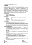
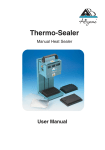
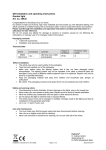
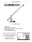
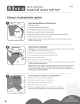
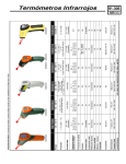
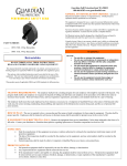
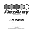
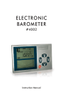
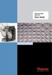
62 Max/62 Max + Infrared Thermometer Calibration Information Introduction The Fluke 62 MAX and 62 MAX + Infrared Thermometers (the Product) can determine the surface temperature by measurement of the infrared energy radiated from the target surface. Note Japanese models indicate Celsius only. Warning To prevent personal injury, read all safety information before you use the Product. Contact Fluke To contact Fluke, call one of the following telephone numbers: • Technical Support USA: 1-800-44-FLUKE (1-800-443-5853) • Calibration/Repair USA: 1-888-99-FLUKE (1-888-993-5853) • Canada: 1-800-36-FLUKE (1-800-363-5853) • Europe: +31 402-675-200 • Japan: +81-03-6714-3114 • Singapore: +65-6799-5566 • Anywhere in the world: +1-425-446-5500 Or, visit Fluke's website at www.fluke.com. To register your product, visit http://register.fluke.com. To download manuals, or to see, print, or download the latest manual supplement, visit http://us.fluke.com/usen/support/manuals. June 2013 ©2013 Fluke Corporation. All rights reserved. 1 62 Max/62 Max + Calibration Information Safety Information A Warning identifies conditions and procedures that are dangerous to the user. A Caution identifies conditions and procedures that can cause damage to the Product or the equipment under test. The symbols used on the Product and in this manual are shown in Table 1. Warning To prevent eye damage and personal injury: • Read all safety Information before you use the Product. • Do not use the Product if it operates incorrectly. • Use the Product only as specified, or the protection supplied by the Product can be compromised. • Before you use the Product, inspect the case. Do not use the Product if it appears damaged. Look for cracks or missing plastic. • See emissivity information for actual temperatures. Reflective objects result in lower than actual temperature measurements. These objects pose a burn hazard. • Do not look directly into the laser with optical tools (for example, binoculars, telescopes, microscopes). Optical tools can focus the laser and be dangerous to the eye. • Do not look into the laser. Do not point laser directly at persons or animals or indirectly off reflective surfaces. • Replace the batteries when the low battery indicator shows to prevent incorrect measurements. • Do not use the Product around explosive gas, vapor, or in damp or wet environments. • Use the Product only as specified or hazardous laser radiation exposure can occur. Table 1. Symbols Symbol Meaning Risk of danger. Important information. See Manual. Warning. Laser. Battery Conforms to China Metrology Certification 2 Symbol Meaning This product complies with the WEEE Directive (2002/96/EC) marking requirements. The affixed label indicates that you must not discard this electrical/electronic product in domestic household waste. Product Category: With reference to the equipment types in the WEEE Directive Annex I, this product is classed as category 9 "Monitoring and Control Instrumentation” product. Do not dispose of this product as unsorted municipal waste. Go to Fluke’s website for recycling information. Conforms to European Union directives. Conforms to relevant Australian standards. Conforms to relevant South Korean EMC standards. Infrared Thermometer Maintenance Maintenance Caution To prevent damage to the Product, do not leave the Product on or near objects of high temperature. Clean the Product Use soap and water on a damp sponge or soft cloth to clean the Product case. Carefully wipe the lens surface with a moist cotton swab. The swab may be moistened with water. See Figure 1. hiy002.eps Figure 1. Clean the Product 3 62 Max/62 Max + Calibration Information Change the Battery To install or change the AA IEC LR06 battery, use a flat-head screwdriver to remove the battery compartment door. Replace the battery as shown in Figure 2. Be sure to observe the correct polarity. hiy001.eps Figure 2. Change the Battery 4 Infrared Thermometer Specifications Specifications 62 MAX Temperature Range 62 MAX + -30 °C to 500 °C -30 °C to 650 °C (-22 °F to 932 °F) (-22 °F to 1202 °F) ≥0 °C: ±1.5 °C or ±1.5 % of reading, whichever is greater ≥0 °C: ±1 °C or ±1 % of reading, whichever is greater (≥32 °F: ±2 °F or ±1 % of reading, whichever is greater) Accuracy (≥32 °F: ±3 °F or ±1.5 % of reading, whichever is greater) (Calibration geometry with ambient temperature 23 °C ±2 °C) ≥ -10 °C to <0 °C: ±2 °C (≥14 °F to <32 °F: ±4 °F) (≥14 °F to <32 °F: ±4 °F) < -10 °C: ±3 °C < -10 °C: ±3 °C (<14 °F: ±6 °F) ≥ -10 °C to <0 °C: ±2 °C (<14 °F: ±6 °F) Response Time (95 %) <500 ms (95 % of reading) Spectral Response 8 to 14 microns Emissivity 0.10 to 1.00 Temperature Coefficient ±0.1 °C/°C or ±0.1 %/°C of reading (whichever is greater) Optical Resolution <300 ms (95 % of reading) 10:1 12:1 (calculated at 90 % energy) (calculated at 90 % energy) Display Resolution 0.1 °C (0.2 °F) Repeatability (% of reading) ±0.8 % of reading or ±1.0 °C (2 °F), whichever is greater Power 1 AA IEC LR06 Battery Battery Life 10 hours with laser and backlight on Weight 255 g (8.99 oz) Size (175 x 85 x 75) mm (6.88 x 3.34 x 2.95) inches Operating Temperature 0 °C to 50 °C (32 °F to 122 °F) Storage Temperature -20 °C to 60 °C (-4 °F to 140 °F), (without battery) Operating Humidity 10 % to 90 % RH non-condensing @ 30 °C (86 °F) Operating Altitude 2000 meters above mean sea level Storage Altitude 12,000 meters above mean sea level Drop Test 3 meters IP Rating IEC 60529: IP 54 Implement Standard Q/SXAV37 Laser Safety IEC 60825-1, Class 2 Electromagnetic Environment IEC 61326-1: Portable ±0.5 % of reading or ±0.5 °C (1 °F), whichever is greater 8 hours with laser and backlight on Applies to use in Korea only: Class A Equipment (Industrial Broadcasting & Communication Equipment) [1] Electromagnetic Compatibility [1] This product meets requirements for industrial (Class A) electromagnetic wave equipment and the seller or user should take notice of it. This equipment is intended for use in business environments and is not to be used in homes. 5 62 Max/62 Max + Calibration Information Performance Verification Tests The subsequent performance tests verify the complete operation of the Product and check the accuracy of each function against Product specifications. If the Product fails any part of the test, calibration adjustment and/or repair is necessary. Product calibration can only be adjusted at the Fluke factory. To return your Product for calibration adjustment, call one of the numbers in the “Contact Fluke” section of this document. Read the entire Performance Tests section before you make any adjustment. Required Equipment Table 2 shows the required equipment necessary for the performance tests. Note Fluke recommends plate blackbodies as verification equipment because cavity blackbodies have small field of view, which could increase uncertainty for a thermometer with low D:S. If cavity blackbodies are used to verify the Product, make sure that the distance between the cavity blackbody opening and the Product is equal to the diameter of the cavity blackbody opening × 2. Where the temperature of the cavity tube near the outside is lower than the temperature of the cavity, readings will be lower. Moving the 62Max closer to the cavity opening may be necessary for the 62 Max to only measure the cavity temperature. If other than Fluke blackbodies are used, the target should be checked for actual radiometric output with a more accurate device, such as a Heitronic KT19-82. Table 2. Required Equipment Item Minimum Use Specifications Calibration Equipment 2.1 Blackbody Range: -10 °C to 100 °C Fluke 4180 2.2 Blackbody Range: 100 °C to 500 °C Fluke 4181 2.3 Blackbody Range: 500 °C to 650 °C Plate Blackbody with 10 cm to 15 cm target. [1] [1] Calibrate with an IR thermometer that has low uncertainty such as KT19 and TRT. Before the Performance Verification Tests Before you do the performance verification tests: • Performance verification tests are to be done within the temperature of 23 ±3 °C and between 25 % and 60 % relative humidity. • Make sure that all required calibration equipment has a valid calibration certificate and/or label. • Make sure that any item(s) substituted for the equipment in Table 2 meets or exceeds the stated minimum use specifications. • The correct radiometric temperature will need to be determined before blackbodies are used to make measurements. • Make sure that the required calibration equipment is allowed a warm-up period as per manufacturer recommendations. See the documentation for the equipment. 6 Infrared Thermometer Performance Verification Tests To prepare the Unit Under Test (UUT) for verification: 1. Visually inspect the UUT outer case for cracks or damage. 2. Open the battery compartment and inspect the battery and battery compartment for corrosion or damage. 3. Install a new AA battery prior to verification. 4. Close the UUT battery compartment door. 5. Set the UUT temperature units for degrees Celsius (°C) if necessary. 6. Push SEL until °C alone is shown. Change by pushing SET. Performance Verification Test Procedures Note The subsequent verification test requires the blackbody emissivity to be set to 0.95 at all temperature points. Note For temperatures below ambient, to reduce the chance of condensation or ice buildup on the emitter plate of the 4180, it is recommended to install a clean dry air or nitrogen gas purge box on the front of the 4180 Blackbody. Although the purge box is recommended, it is optional. If temperature measurements are made without a purge box, refer to the 4180 User Manual for how to make proper temperature measurements below ambient. See Figure 3. hiy003.eps Figure 3. Aim the 62 Max + for Verification 7 62 Max/62 Max + Calibration Information 1. Set blackbody emissivity and temperature for the first temperature listed in Table 3. Allow adequate time for the blackbody to stabilize. See the blackbody documentation. 2. Position the UUT at the correct the distance from the blackbody listed in Table 3. Center the UUT laser(s) on the blackbody emitter plate. For the 62 MAX +, make sure that the midpoint of the two laser spots is centered on the blackbody plate. The 62 Max uses one laser. 3. Push and hold the UUT trigger for 5 to 6 seconds. 4. Release the trigger. 5. Record the UUT indication. 6. Move to a location that is not centered on the blackbody. 7. Make sure the UUT reading is within the limits listed in Table 3. 8. Repeat steps 1 through 7 for the remaining temperatures listed in the Temperature column of Table 3. The 62 Max is specified to 500 °C. 461 °C is the last temperature point to verify. 9. Set blackbodies to nominal values. Table 3. Verification Tests Distance (cm) [1] Temperature (°C) Emissivity 62 Max Limits (°C) 62 Max + Limits (°C) Fluke 4180 points 28 -10 0.95 -12.0 to -8.0 -12.0 to -8.0 28 0 0.95 -1.5 to 1.5 -1.0 to 1.0 28 65 0.95 63.5 to 66.5 64.0 to 66 28 250 0.95 246. 2 to 253.8 247.5 to 252.5 28 461 0.95 454.1 to 467.9 456.3 to 465.6 Fluke 4181 point Fluke 62 Max + only above 500 °C 25.5 580 0.95 574.2 to 585.8 [1] Distance is calculated based on the target size. Typically a spot size that is about 1/2 the target size provides the best results. Note Fluke recommends plate blackbodies as verification equipment because cavity blackbodies have small field of view, which could increase uncertainty for a thermometer with low D:S. If cavity blackbodies are used to verify the Product, make sure that the distance between the cavity blackbody opening and the Product is equal to the diameter of the cavity blackbody opening × 2. Where the temperature of the cavity tube near the outside is lower than the temperature of the cavity, readings will be lower. Moving the 62Max closer to the cavity opening may be necessary for the 62 Max to only measure the cavity temperature. Temperature verification is complete. If the Product does not pass the performance verification tests, calibration adjustment or repair is necessary. Product calibration can only be adjusted by Fluke. To return your Product for calibration adjustment, call one of the numbers in the “Contact Fluke” section of this document. Blackbody Layout Make sure that the distance between two blackbodies is more than 1 meter. Forced air or HVAC vents should not be near the surface of the radiation source. Do not have two blackbodies work face to face. For more detail about blackbody use, see the Fluke 4180 Technical Guide. 8 Infrared Thermometer User-Replaceable Parts User-Replaceable Parts To order replacement parts, call one of the numbers in the “Contact Fluke” section of this document. Userreplaceable parts are listed in Table 4. Table 4. User-Replaceable Parts Description Fluke Part Number Quantity Fluke 62 Max Rear Decal 4134155 1 Fluke 62 Max + Rear Decal 4134162 1 Fluke 62 Max Battery Door Assembly 4103199 1 Battery AA Alkaline 1311933 1 Fluke 62 Max + Carabineer Solid Aluminum, 2.3 in with spring hinge black finish 4149787 1 62 Max/62 Max + Users Manual 4060712 1 LIMITED WARRANTY AND LIMITATION OF LIABILITY This Fluke product will be free from defects in material and workmanship for three years from the date of purchase. This warranty does not cover fuses, disposable batteries, or damage from accident, neglect, misuse, alteration, contamination, or abnormal conditions of operation or handling. Resellers are not authorized to extend any other warranty on Fluke’s behalf. To obtain service during the warranty period, contact your nearest Fluke authorized service center to obtain return authorization information, then send the product to that Service Center with a description of the problem. THIS WARRANTY IS YOUR ONLY REMEDY. NO OTHER WARRANTIES, SUCH AS FITNESS FOR A PARTICULAR PURPOSE, ARE EXPRESSED OR IMPLIED. FLUKE IS NOT LIABLE FOR ANY SPECIAL, INDIRECT, INCIDENTAL OR CONSEQUENTIAL DAMAGES OR LOSSES, ARISING FROM ANY CAUSE OR THEORY. Since some states or countries do not allow the exclusion or limitation of an implied warranty or of incidental or consequential damages, this limitation of liability may not apply to you. Fluke Corporation P.O. Box 9090 Everett, WA 98206-9090 U.S.A. Fluke Europe B.V. P.O. Box 1186 5602 BD Eindhoven The Netherlands 11/99 9 62 Max/62 Max + Calibration Information 10