1
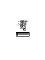
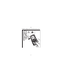
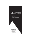
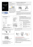
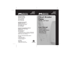
PM53 Automatic Pocket Meter Users Manual • • • • Mode d’emploi Bedienungshandbuch Manual d’Uso Manual de uso PN 2153036 August 2004 2004 Meterman Test Tools. All rights reserved. Printed in Taiwan 1 3 2 Press for 2 seconds to turn meter on. SELECT A LCD display B SELECT-button to select alternate functions and turn the power off and on. C Permanently attached red test lead for positive (+) polarity and black test lead for ground reference (-) PM53 Pocket Meter Introduction Safety Information Symbols Used in this Manual Turning the Meter On and Off Making Measurements AutoTectTM Mode Continuity, Audible With Symbolic Display Electric Field EF-Detection, VolTect Voltage Resistance Frequency Capacitance Product Maintenance Maintenance Cleaning Troubleshooting Battery Replacement Limited Warranty and Limitation of Liability Repair Specifications 1 2 2 3 3 4 5 5 5 8 8 8 8 8 8 8 9 9 10 10 11 English Contents Introduction This unique meter has a full complement of features in a compact package only 3/8 inch deep and weighing less than 3 oz. The essential shirt-pocket size meter for portability, Model PM53 is fully autoranging and has an oversized, easy-to-read digital display. It offers the AutoTect™ feature that guides the meter to display AC volts, DC volts or resistance based on what you are measuring. Also offered is VolTect™, a built-in non-contact voltage detector of AC voltages. Although very small, this meter is fully UL safety rated to CAT III levels. The Meterman PM53 includes measurement extras such as capacitance, frequency and continuity plus safety extras such as transient protection to 4 kV and overload protection to either 450 V. Safety Information • The PM53 Digital Multimeter is certified for cULus and EN61010-1:2001; CAT II 450 V, CAT III 300 V, class 2 and pollution deg. 2. • This instrument is EN61010-1 certified for Installation Category II (450 V). It may only be used to make measurements on energy limited circuits within equipment and not directly connected to mains. • This instrument is EN61010-1 certified for Installation Category III (300 V). It is recommended for use with local level power distribution, appliances, portable equipment, etc., where only smaller transient overvoltages may occur, and not for primary supply lines, overhead lines and cable systems. • Do not exceed the maximum overload limits per function (see specifications) nor the limits marked on the instrument itself. Never apply more than 450 V between the test lead and earth ground. • Inspect the DMM, test leads and accessories before every use. Do not use any damaged part. • Never ground yourself when taking measurements. Do not touch exposed circuit elements or test probe tips. • Do not operate the instrument in an explosive atmosphere. • Exercise extreme caution when: measuring voltage >20 V // current >10 mA // AC power line with inductive loads // AC power line during electrical storms // current, when the fuse blows in a circuit with open circuit voltage > 450 V // servicing CRT equipment. • Remove test leads from circuit before opening the case. • Always measure current in series with the load – NEVER ACROSS a voltage source. 2 Symbols Used in this Manual N Battery W Refer to the manual T Double insulated X Dangerous Voltage F Direct Current J Earth Ground B Alternating Current R Audible tone P Complies with EU directives > Underwriter Laboratories, Inc. I Fuse Turning the Meter On and Off • • Press the SELECT button for approximately 2 seconds to turn the meter on. To turn the meter off, press the SELECT button until the display goes blank. 3 Making Measurements All measurements described in this manual use the Red test lead for positive (+) polarity and Black test lead for Ground reference (-) unless otherwise specified AutoTect mode is the default function when the meter is first turned on. Press the SELECT button momentarily to select and step through the functions: • AutoTect • Continuity • EF • ACV • DCV • Ω • Hz • Cx • AutoTect 4 AutoTectT Mode The AutoTect feature automatically selects measurement function of V dc, V ac, or resistance based on the input via the test leads. ● With no input, the meter displays Auto when it is ready. ● With no voltage signal but a resistance below 6 MΩ is present, the meter displays the resistance value. ● When a signal above the threshold of 1.2 V dc or 1.5 V ac up to the rated 450 V is present, the meter displays the appropriate voltage value in dc or ac, whichever larger in peak magnitude. ● The AutoTecttest mode input impedance is lower than most digital multimeters and LoZ is displayed on the LCD. This may cause reading errors if the circuit being measured is sensitive to the meter input impedance. Input impedance is approximately 160 Ω, helping determine if voltage is from leakage (so-called “ghost” voltages) or a hard connection. “Ghost” voltages will be zeroed out by the low input impedance. ● Overload-Alert Feature When above rated 450 V is present, the meter displays OL with a warning beep tone. Disconnect the test leads from the signal immediately to avoid hazards. • Range-Lock Feature When a measurement reading is displayed in the AutoTect mode, press the SELECT button momentarily to lock the function-range. The LCD annunciator Auto turns off. Range-lock can speed up repetitive measurements. Press the SELECT button momentarily again to return to AutoTect mode. When making resistance measurements in AutoTect mode, an unexpected display of voltage readings alerts you that the circuit under test is still energized. Continuity, Audible With Symbolic Display With Auto on the LCD, press the SELECT button once to select Continuity function. The meter will show a symbolic open-switch display .A continuous beep tone and a symbolic closed-switch indicates a closed circuit. Continuity is used for checking wiring connections and operation of switches. Electric Field EF-Detection, VolTect With Auto displayed on the LCD, press the SELECT button momentarily 2 times to select the EF-Detection feature. The meter displays EF. Signal 5 strength is indicated as a series of bargraph segments on the display and variable beep tones. See the VolTect specifications later in this manual for a complete description of the bar graph indicators. • Voltect An antenna is located at the top left corner of the meter, which detects electric field surrounding current-carrying conductors. It is ideal for tracing live wiring connections, locating wiring breakage and to distinguish between live or earth connections. • Probe-Contact EF-Detection For more precise indication of live wires, such as distinguishing between live and ground sockets, use the V ac manual function selection for direct contact voltage measurements. 6 Note For Maximum sensitivity, hold the meter away from the VolTect corner. T LEC SE 7 Voltage With Auto on the LCD, press the SELECT button 3 times to select V ac function. The meter displays LoZBV when it is ready.This function is auto-ranging. With Auto on the LCD, press the SELECT button 4 times to select V dc. The meter displays LoZ V when it is ready. This function is auto-ranging. Resistance With Auto on the LCD, press the SELECT button 5 times to select resistance function, The meter displays MΩ when it is ready. This function is auto-ranging. Frequency With Auto on the LCD, press the SELECT button 6 times to select frequency function, The meter displays Hz when it is ready. This function is auto-ranging. Capacitance With Auto on the LCD, press the SELECT button 7 times to select capacitance function, The meter displays nF when it is ready. This function is auto-ranging. Return to Auto Press the SELECT button 8 times to return to AutoTect test mode. Product Maintenance Maintenance Do not attempt to repair this meter. It contains no user serviceable parts. Repair or servicing should only be performed by qualified personnel. Cleaning Periodically wipe the case with a damp cloth and mild detergent; do not use abrasives or solvents. If the meter is not to be used for periods of longer than 60 days, remove the battery and store it separately 8 Troubleshooting If the instrument fails to operate, check battery, leads, and replace battery as necessary. Double-check operating procedure as described earlier in this manual. If the display locks up, press the SELECT button for approximately 6 seconds to reset the microprocessor. If the instrument’s voltage-resistance input is subjected to high voltage transient (mostly caused by lightning or switching surge to your system) by accident or abnormal conditions of operation, the series fusible resistors will react (become high impedance) like fuses to protect the user and the instrument. Most measuring functions through this input will then be open circuit. The series fusible resistors and the spark gaps should then be replaced by qualified technician. Refer to the LIMITED WARRANTY section for obtaining warranty or repairing service. Battery Replacement If the meter starts up with persistent resetting display or with low battery icon N turns on, replace the battery. The meter uses one 3 V coin battery IEC-CR2032. To replace the battery 1. Turn off the meter. 2. Disconnect the test leads from live circuits. 3. Loosen the screwon the case bottom. 4. Lift the end of the case bottom nearest the input test leads until it unsnaps from the case top. Replace the battery cover and tighten the screw. Recycle the battery using approved methods. 5. Replace the battery. Observe battery polarities with positive (+) faces up (towards the case bottom). Replace the case bottom, and ensure that the snap on the case top (near the LCD side) is engaged. 6. Replace and tighten the screw. XWWARNING To avoid electrical shock, disconnect test leads from live circuits before opening the case. Do not operate with open case. 9 Limited Warranty and Limitation of Liability Your Meterman product will be free from defects in material and workmanship for 1 year from the date of purchase. This warranty does not cover fuses, disposable batteries or damage from accident, neglect, misuse, alteration, contamination, or abnormal conditions of operation or handling. Resellers are not authorized to extend any other warranty on Meterman’s behalf. To obtain service during the warranty period, return the product with proof of purchase to an authorized Meterman Test Tools Service Center or to a Meterman dealer or distributor. See Repair Section for details. THIS WARRANTY IS YOUR ONLY REMEDY. ALL OTHER WARRANTIES WHETHER EXPRESS, IMPLIED OR STAUTORY - INCLUDING IMPLIED WARRANTIES OF FITNESS FOR A PARTICULAR PURPOSE OR MERCHANTABILITY, ARE HEREBY DISCLAIMED. MANUFACTURER SHALL NOT BE LIABLE FOR ANY SPECIAL, INDIRECT, INCIDENTAL OR CONSEQUENTIAL DAMAGES OR LOSSES, ARISING FROM ANY CAUSE OR THEORY. Since some states or countries do not allow the exclusion or limitation of an implied warranty or of incidental or consequential damages, this limitation of liability may not apply to you. Repair All test tools returned for warranty or non-warranty repair or for calibration should be accompanied by the following: your name, company’s name, address, telephone number, and proof of purchase. Additionally, please include a brief description of the problem or the service requested and include the test leads with the meter. Non-warranty repair or replacement charges should be remitted in the form of a check, a money order, credit card with expiration date, or a purchase order made payable to Meterman Test Tools. In-Warranty Repairs and Replacement – All Countries Please read the warranty statement that follows, and check your battery before requesting repair. During the warranty period any defective test tool can be returned to your Meterman Test Tools distributor for an exchange for the same or like product. Please check the “Where to Buy” section on www.metermantesttools.com for a list of distributors near you. Additionally, in the United States and Canada In-Warranty repair and replacement units can also be sent to a Meterman Test Tools Service Center (see below for address). 10 Non-Warranty Repairs and Replacement – US and Canada Non-warranty repairs in the United States and Canada should be sent to a Meterman Test Tools Service Center. Call Meterman Test Tools or inquire at your point of purchase for current repair and replacement rates. In USA In Canada Meterman Test Tools Meterman Test Tools 1420 75th Street SW 400 Britannia Rd. E. Unit #1 Everett, WA 98203 Mississauga, ON L4Z 1X9 Tel: 888-993-5853 Tel: 905-890-7600 Fax: 425-446-6390 Fax: 905-890-6866 Non-Warranty Repairs and Replacement – Europe European non-warranty units can be replaced by your Meterman Test Tools distributor for a nominal charge. Please check the “Where to Buy” section on www.metermantesttools.com for a list of distributors near you. European Correspondence Address* Meterman Test Tools Europe P.O. Box 1186 5602 BD Eindhoven The Netherlands *(Correspondence only – no repair or replacement available from this address. European customers please contact your distributor.) Specifications General Specifications Display and Update Rate: 3-5/6 digits 6000 counts; Updates 5 per second nominal Operating Temperature: 0 °C - 40 °C Operating Relative Humidity: Maximum 80% R.H. up to 31 °C, decreasing linearly to 50% R.H. at 40 °C Altitude: Operation below 2000 m Storage Temperature: -20 °C ~ 60 °C, < 80% R.H. (with battery removed) Temperature Coefficient: Nominal 0.15 x (specified accuracy)/ °C @ (0 °C ~ 18 °C or 28 °C ~ 40 °C), or otherwise specified Sensing: Average sensing Overload Protection: 450 V dc and V ac rms Low Battery: Below approx. 2.4 V 11 Power Supply: 3 V standard button battery x 1 (IEC-CR2032; ANSI-NEDA5004LC) Power Consumption (typical): 2 mA APO Consumption (typical): 2.2 µA APO Timing: Idle for 3 minutes Dimension / Weight L 113 mm x W 53 mm x H 10.2 mm / Approx. 78 gm Special Features AutoTect (Automatic V and Ω selection) and VolTect (Electric Field Detection) Agency Approvals P > Safety: Meets IEC61010-1, UL61010B-1, CAN/CSA-C22.2 No. 1010.1-92, CAT II 450 V and CAT III 300V, Pollution Degree 2, Class 2 E.M.C. Meets EN61326 (1997, 1998/A1), EN61000- 4-2 (1995), and EN61000-4-3 (1996). This product complies with requirements of the following European Community Directives: 89/ 336/ EEC (Electromagnetic Compatibility) and 73/ 23/ EEC (Low Voltage) as amended by 93/ 68/ EEC (CE Marking). However, electrical noise or intense electromagnetic fields in the vicinity of the equipment may disturb the measurement circuit. Measuring instruments will also respond to unwanted signals that may be present within the measurement circuit. Users should exercise care and take appropriate precautions to avoid misleading results when making measurements in the presence of electronic interference. Accessories Silicon holster, Battery installed, and User’s manual Optional Accessories VC3 soft carrying case with zipper Electrical Specifications (Accuracy @ 23 °C +/- 5 °C and < 75% R.H.) RF Field @ 3 V/m: Specified accuracy + 45 d (Capacitance not specified) 12 DC Voltage Range Accuracy 6.000 V ±(0.5%+3 dgt) 60.00 V ±(1.0%+5 dgt) 450.0 V ±(1.2%+5 dgt) Input Impedance: AutoTect Lo-Z V dc: 160 kΩ, 160 pF nominal MRR: > 30dB @ 50 Hz/60 Hz CMRR: > 100dB @ DC, 50 Hz/60 Hz; Rs=1 kΩ V dc AutoTect Threshold: > +1.2 V dc or < -0.6 V dc nominal AC Voltage Range Accuracy 50 Hz – 60 Hz ±(1.5%+5 dgt) 6.000 V, 60.00 V, 450.0 V CMRR: > 60 dB @ dc to 60 Hz, Rs=1 kΩ Input Impedance: AutoTect Lo-Z V ac: 160 kΩ, 160 pF nominal Hi-Z V ac: 5 MΩ, 90 pF nominal ACV AutoTect Threshold: > 1.5 V ac (50 Hz/60 Hz) nominal 13 Capacitance Range1 Accuracy2 100.0 nF, 1000 nF, 10.00 µF, 100.0 µF 3) ±(3.5%+6 dgt) 4 1) Accuracy below 50 nF is not specified Accuracies with film capacitor or better Top range. Updates > 1 minute on large values 4) Specified with battery voltage above 2.8 V (half full battery). Accuracy decreases gradually to 12% at low battery warning voltage of approx. 2.4 V. 2) 3) Resistance Range1 Accuracy2 6.000 kΩ ±(1.2%+6 dgt) 60.00 KΩ, 600.0 KΩ ±(1.0%+4 dgt) 6.000 MΩ ±(2.0%+4 dgt) Open Circuit Voltage: 0.4 V dc typical 1)AutoTect is for 6.000 kΩ ~ 6.000 MΩ ranges; 2)Add 40 d to specified accuracy when reading is below 20% of range 14 Frequency Range1 100 Hz, 1 kHz, and 10 kHz 1 Accuracy Specified At ±(0.5%+4 dgt) < 20 V Sine-rms Sensitivity (Sine-rms): Hz in Auto-VΩ position:> 3 V Voltect Typical Voltage Bar Graph Indication 15 V to 55 V - 30 V to 85 V -- 45 V to 145 V --- 75 V to 190 V ---- above 105 V ----- Indication: Bar graph segments & audible beep tones proportional to field strength Detection Frequency: 50/60 Hz Detection Antenna: Top left corner of the meter Audible Continuity Tester Open Circuit Voltage: 0.4 V dc typical Audible Threshold: >175 Ω ± 125 Ω 15 16