1
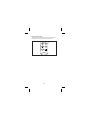
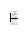
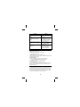
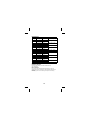
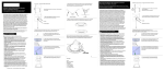
TMD90
TMD90
®
®
®
®
U.S. Service Center
Canadian Service Center
Dual Input
Digital
Thermometer
European Correspondence Address*
User Manual
Meterman Test Tools
1420 75th Street SW
Everett, WA 98203
Tel: 888-993-5853
Fax: 425-446-6390
Meterman Test Tools
400 Britannia Rd. E. Unit #1
Mississauga, ON L4Z 1X9
Tel: 905-890-7600
Fax: 905-89-6866
Meterman Test Tools Europe
P.O. Box 1186
5602 BD Eindhoven
The Netherlands
*Correspondence only - no repair or replacement
available from this address. European customers
please contact your distributor.
Visit www.metermantesttools.com for
• Catalog
• Application notes
• Product specifications
• Product manuals
PN 2099366
September 2003
© Wavetek Meterman Test Tools.
All rights reserved. Printed in China.
Please Recycle
• Mode d'emploi
• Bedienungshandbuch
• Manuale d'Uso
• Manual de uso
Document Dimensions: 3 x 5 inches
TMD90 Dual Input Thermometer
Safety Information .............................................................................. 2
Symbols Used in this Manual ........................................................... 2
Introduction........................................................................................ 3
Display and Controls ........................................................................... 4
Functions............................................................................................ 5
Auto Power Off ( Sleep Mode ) ......................................................... 5
Change Thermocouple Type ............................................................. 5
Using the Pushbuttons..................................................................... 6
RS-232 Output................................................................................. 7
Troubleshooting.................................................................................. 8
Replacing the Battery .......................................................................... 9
9 V ac Adapter .................................................................................... 9
Repair............................................................................................... 10
WARRANTY...................................................................................... 11
Thermocouple Definitions ................................................................. 11
Specifications ................................................................................... 12
Additional Specifications ................................................................... 12
1
English
Contents
Safety Information
•
•
•
•
•
•
Place ONLY thermocouples in the thermocouple input.
Make sure your meter is configured for the thermocouple type to
be used.
Be sure the thermocouple you use can withstand the temperature
extreme it will be exposed to.
Properly maintain the meter and calibrate it regularly
Use the thermometer only as specified in this manual, or the
protection provided by the thermometer might be impaired.
Replace the battery as soon as BAT appears to avoid false readings
that can lead to electric shock and injury.
Warning
Supplied thermocouple is not intended for contact
with liquids or live electrical circuits.
XW
Symbols Used in this Manual
X
T
P
W
J
Dangerous Voltage
Double insulated
Complies with EU
directives
2
Refer to the manual
Earth Ground
Introduction
The Model TMD90 dual input thermometer accepts Type K, J, T, R, S,
and E thermocouples. With a triple display screen to view measurement
results and relative time clock. Optional RS-232 software and cable
allows collection of real time data to a PC for further analysis or
reports.
TMD90 displays all LCD (liquid crystal display) segments for
approximately 3 seconds when it is first turned on and then provides
information on any connected thermocouples. Numerous viewing
combinations are available. The LCD is divided into three distinct
sections; one large (Primary) top screen and two smaller bottom
screens (Secondary and Relative Clock).
The three display areas are continually updated with the temperature
measurements and relative time information. There are several options
regarding how and what information is presented on the LCD.
• Temperature readings are easily toggled between Fahrenheit and
Celsius.
• A backlight illuminates the LCD for viewing in low light areas.
button will freeze the upper display data while allowing
• The
the lower displays to continue updating Information.
• A low battery indicator is also displayed as appropriate.
• The meter defaults to the last mode selected when turned off.
Note: If no thermocouples are connected, four dashes(----) appear in
the temperature display.
Box Contents
TMD90 Thermometer
1
Type K thermocouple probe
1
Users Manual
1
Hard plastic carry case
1
9 V battery (installed)
1
A
3
Display and Controls
10 (T2)
10 (T1)
2
3
4
1
5
7
6
8
11
9
6
12
13
A
B
C
D
E
F
G
H
I
J
K
L
M
REC Relative clock is active for recording min and max
temperature occurences or for time stamp purposes.
MAX/MIN Maximum or minimum temperature
measurements are being monitored.
HOLD/REL Freezes primary display or establishes a relative
zero for the primary display information.
BAT Low battery indicator.
°C °F Displays temperature in either degrees Celsius or
degrees Fahrenheit.
T1-T2 Toggles screen niformation from T1 (Primary)/ T 2
(Secondary) to T2 (Primary) / T1 (Secondary) ,then to T 1-T 2
(Differential) on Primary and alternating T1/T2 temperatures
on Secondary display.
Primary data display. Displays T1, T2, or T1-T2( temperature
differential -TD ) or a relative zero of T1, T2, or TD.
KJTRSE Selects proper input reference for thermocouple in
use. T1 and T2 must be the same thermocouple type.
Secondary data display. Displays T2,T1 or T1 and T2
temperatures.
Thermocouple input. Positive and negative polarized plugs for
the thermocouple probes used ( Blade type ); T1 on the left
,T2 on the right.
Relative clock display. Displays time in hours, minutes, and
seconds (HHMMSS) when REC is pressed and the relative
time that MIN or MAX data was recorded.
RS-232 output port. Optional software and cable – PN
TM-SW.
AC to DC converter input.
4
W
Caution
Read all Safety Information before using this
thermometer.
Functions
Auto Power Off (Sleep Mode)
DA
The TMD90 shuts off automatically approximately 20 minutes after
being turned on. For recording or operating over longer periods of time
you can disable the sleep mode by pressing
and
simultaneously while power on. When "n" then appear in the center of
the screen you can release the On. Auto power off is disabled when you
turn off the meter.
E DC
E
Change Thermocouple Type
Press
and
simultaneously for 2 or more seconds until K
appears. Press the
button the type of probe cycles through K
(the default), J, T, R, S, and E types. The current mode is displayed on
, an "S" will appear in the center of
the left side of the LCD. press
the screen.
5
Using the Pushbuttons
The display defaults to the mode last used. For your convenience the
meter defaults to the settings used during the last operation.
REC
HOLD
REL
˚C ˚F
T1 T2
6
Use the pushbuttons to control operation of the TMD90. The table
assumes the TMD90 has been powered on with two thermocouples
installed and is set to display (default) T1 on the primary display, type
K thermocouple, and Record off.
DA
Button
F
B
C
E
Description
Turns the meter on and off.
Press and release HOLD/REL and the Primary display
(T1, T2, or T1-T2) freezes with HOLD displayed on top;
Press for two or more seconds REL appears on top of
LCD and the REL Primary display indicates the relative
zero. Relative zero causes the value of the primary
display to show as "000.0" , then only the amount of
temperature change will be indicated. Relative
temperatures can be recorded. Press HOLD/REL again
and the unit returns to default.
Press momentarily and the Primary display changes to
T2 (Secondary screen displays T1); press momentarily
again and it displays T1-T2; Secondary display
alternates between T1 and T2; Press momentarily again
and the instrument returns to default.
Press momentarily and the backlight illuminates for
approximately 30 seconds then turns off.
Press momentarily and the unit toggles between
Fahrenheit (the default) and Celsius temperatures; The
current mode is indicated on the right side of the LCD.
Press momentarily and the Relative Clock starts in the
lower right screen. All other button functions are locked
out except Power and Backlight. T1, T2, or T1-T2 is
displayed on the Primary screen; The Secondary screen
continues to update. Press momentarily again and the
unit cycles through MAX and MIN (Maximum and
Minimum recorded temperatures) and back to current
temperature; The record mode is displayed on the LCD.
Press and hold for three seconds to turn off the record
function.
RS-232 Output
With optional software and cable, P/N TM-SW, the TMD90 can output
measurement results to a computer with operating systems of Window
95/98/NT/2000/XP/ME. Features of the software:
• Record up to 16,000 sample readings with real-time clock memory.
• Programmable sample interval from 1 sec to 3,600 sec.
• User defined maximum and minimum alarm settings.
• Allow further analysis by downloading data to computer program.
• All data is saved in .txt format for easy transformation into another
software program.
7
Troubleshooting
Problem
Thermometer does not turn
on.
Solution
• Check battery voltage and
replace discharged battery.
• Verify that battery clips grip
the battery post tightly.
• Insert missing
thermocouple.
Dashes appear in the T1 and
T2 data screens.
Dashes appear in T1 and/or T2
data screens with
thermocouples inserted.
• Measure resistance of
thermocouples to ensure
they are not broken
internally.
• Clean the thermocouple
and restart.
Temperature drifts from a
known value in a controlled
environment
• Verify that thermocouple
type matches the displayed
icon.
• Clean and dry the
thermocouple blades and
allow to air dry.
• Confirm temperature with a
known good thermocouple.
Replace the defective
thermocouple if required.
8
E
Problem
Relative clock does not start
when you push the
button.
Dashes appear during a review
of the maximum recorded
value.
Solution
• Verify that the
thermocouple is inserted
correctly.
• Thermocouple is not
acknowledged. Check for
intermittent or momentary
thermocouple removal.
• Check for HOLD icon on
the display. Press
button firmly.
• Press
and
simultaneously before
power on to disable the
Auto power off feature.
A
A
D A
Data continues to update after
you press the
button.
Instrument turns off while
recording.
Replacing the Battery
Replace the 9 V battery when:
• BAT appears on the right side of the display.
• The meter will not turn on.
• BAT appears when you turn on the backlight.
Even if the battery was recently replaced, check the voltage level if there
is no response from the meter.
To replace the battery
1. Remove all thermocouples from the top of the meter.
2. Lay the instrument face down on a clean, flat surface.
3. Loosen the screw and remove the battery door.
4. Replace the battery.
5. Replace the battery door and tighten the screw.
Remove the battery if you do not plan to use the meter for a month or
more. Do not leave the battery in a meter that may be exposed to
temperature extremes.
9 V ac Adapter
For long term measurement recording, a 9 V AC adapter can be used in
place of the battery. This can be purchased at any electronics store
using these specs: Miniature power plug with inner conductor positive
and outer conductor negative, 500 mA current rating. The 9 V battery
can be left in the TMD90 when using the AC adapter.
9
Repair
All test tools returned for warranty or non-warranty repair or for
calibration should be accompanied by the following: your name,
company’s name, address, telephone number, and proof of purchase.
Additionally, please include a brief description of the problem or the
service requested and include the test leads with the thermometer.
Non-warranty repair or replacement charges should be remitted in the
form of a check, a money order, credit card with expiration date, or a
purchase order made payable to Meterman Test Tools.
In-Warranty Repairs and Replacement – All Countries
Please read the warranty statement that follows, and check your
batteries and fuses before requesting repair. During the warranty
period any defective test tool can be returned to your Meterman Test
Tools distributor for an exchange for the same or like product. Please
check the “Where to Buy” section on www.metermantesttools.com for
a list of distributors near you. Additionally, in the United States and
Canada In-Warranty repair and replacement units can also be sent to a
Meterman Test Tools Service Center (see below for address).
Non-Warranty Repairs and Replacement – US and Canada
Non-warranty repairs in the United States and Canada should be sent to
a Meterman Test Tools Service Center. Call Meterman Test Tools or
inquire at your point of purchase for current repair and replacement
rates.
In USA
In Canada
Meterman Test Tools
Meterman Test Tools
1420 75th Street SW
400 Britannia Rd. E. Unit #1
Everett, WA 98203
Mississauga, ON L4Z 1X9
Tel: 888-993-5853
Tel: 905-890-7600
Fax: 425-446-6390
Fax: 905-890-6866
Non-Warranty Repairs and Replacement – Europe
European non-warranty units can be replaced by your Meterman Test
Tools distributor for a nominal charge. Please check the “Where to
Buy” section on www.metermantesttools.com for a list of distributors
near you.
European Correspondence Address*
Meterman Test Tools Europe
P.O. Box 1186
5602 BD Eindhoven
The Netherlands
*(Correspondence only – no repair or replacement available from this
address. European customers please contact your distributor.)
10
WARRANTY
The TMD90 Dual Input Thermometer is warranted against any defects
of material or workmanship within a period of one (1) year following
the date of purchase of the thermometer by the original purchaser or
original user. Any thermometer claimed to be defective during the
warranty period should be returned with proof of purchase to an
authorized Meterman Test Tools Service Center or to the local
Meterman Test Tools dealer or distributor where your thermometer
was purchased. See Repair section for details. Any implied warranties
arising out of the sale of a Meterman Test Tools thermometer,
including but not limited to implied warranties of merchantability and
fitness for a particular purpose, are limited in duration to the above
stated one (1) year period. Meterman Test Tools shall not be liable for
loss of use of the thermometer or other incidental or consequential
damages, expenses, or economical loss or for any claim or claims for
such damage, expenses or economical loss. Some states do not allow
limitations on how long implied warranties last or the exclusion or
limitation of incidental or consequential damages, so the above
limitations or exclusions may not apply to you. This warranty gives you
specific legal rights, and you may also have other rights which vary
from state to state.
Thermocouple Definitions
Type
J
K
R
S
T
E
Alloy
Iron
Fe
Nickel-Chromium
(Chromel)
Ni-Cr
Platinum-13% Rhodium
Pt-13% Rh
Platinum-10% Rhodium
Pt-10% Rh
Copper
Cu
Nickel-Chromium
(Chromel)
Ni-Cr
11
Alloy
Copper-Nickel
(Constantan)
Cu-Ni
Nickel-Aluminum
Ni-AL
Platinum
Pt
Platinum
Pt
Copper-Nickel
(Constantan)
Cu-Ni
Copper-Nickel
(Constantan)
Cu-Ni
Specifications
T/C Type
Range
K
-200 to 650 °C
651 to 1370 °C
-328 to 1000 °F
1001 to 2498 °F
-200 to 500 °C
501 to 760 °C
-328 to 940 °F
941 to 1400 °F
-200 to 390 °C
-328 to 730 °F
0 to 1000 °C
1001 to 1760 °C
32 to 1000 °F
1001 to 3200 °F
-200 to 380 °C
381 to 736 °C
-328 to 720 °F
721 to 1832 °F
J
T
R/S
E
Resolution
0.1 °C
1.0 °C
0.1 °F
1.0 °F
0.1 °C
1.0 °C
0.1 °C
1.0 °F
0.1 °C
0.1 °F
0.1 °C
1.0 °C
0.1 °F
1.0 °F
0.1 °C
1.0 °C
0.1 °F
1.0°F
Accuracy
(0.1% rdg + 0.7 °C)
(0.1% rdg + 1.4 °F)
(0.1% rdg + 0.7 °C)
(0.1% rdg + 1.4 °F
(0.1% rdg + 0.7 °C)
(0.1% rdg + 1.4 °F)
(0.3% rdg + 0.7 °C)
(0.1% rdg + 1.4 °F)
(0.3% rdg + 0.7 °C)
(0.1% rdg + 1.4 °F)
Additional Specifications
OPERATING CONDITIONS
0 to 50 °C (32 to 122 °F) at 0 to 85 % relative humidity
(non-condensing)
Ambient Coefficient
0 to 18 °C and 28 to 50 °C (Ambient temperatures) For each °C
ambient below 18 °C or above 28 °C, add the following tolerance into
the accuracy spec: 0.01% of reading +0.03 °C (0.01% of reading
+0.06 °F).
12