1
Acknowledgements
Design Team
The UKRAA VLF Receiver design is a combination of public domain
material and original improvements by BAA members John Cook and
Peter King. The circuit board layout was undertaken by John Cook.
Contributors
The following authors have contributed to the VLF Receiver Kit Assembly
Manual: Andrew Lutley, Alan Melia, Dr Laurence Newell, Norman Pomfret.
Issue 1 2010 January
1
© UKRAA
Table of Contents
Introduction.........................................................................................................................3
UKRAA.............................................................................................................................3
The UKRAA VLF Receiver..................................................................................................3
Assembly Instructions..........................................................................................................4
Tools Required.................................................................................................................4
Kit Contents.....................................................................................................................4
Printed Circuit Board (PCB)...............................................................................................5
Assembly Sequence..........................................................................................................5
Pre-installed Components................................................................................................6
Install the Resistors..........................................................................................................6
Install the Capacitors.......................................................................................................8
Miscellaneous..................................................................................................................9
Testing..............................................................................................................................12
Visual Inspection............................................................................................................12
Resistance Tests............................................................................................................12
Power-up Tests..............................................................................................................13
Soldering Guide.................................................................................................................13
Technique......................................................................................................................13
Some Further Advice......................................................................................................14
Examples of Soldered Joints...........................................................................................15
Simple Assembly Frame..................................................................................................17
Cleaning the Circuit Board..............................................................................................18
Correcting Mistakes.......................................................................................................18
Appendix 1 - Component List............................................................................................19
Appendix 2 – Resistor Colour Codes...................................................................................21
Appendix 3 – VLF Receiver PCB Layout................................................................................23
Appendix 4 – VLF Receiver Circuit Diagram........................................................................24
Appendix 5 – Regulatory Compliance.................................................................................25
Contacts ...........................................................................................................................26
Revision History.................................................................................................................27
Outstanding Work..........................................................................................................27
Issue 1 2010 January
2
© UKRAA
Introduction
UKRAA
The UK Radio Astronomy Association (UKRAA) is a non-profit-making charitable company
limited by guarantee. It was established by the Radio Astronomy Group of the British
Astronomical Association (BAA) to facilitate the production and sale of radio astronomy
products.
Any suggestions or recommendations for improvement of this Manual would be appreciated.
See the Contacts page for further details.
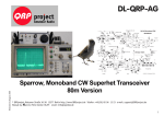
The UKRAA VLF Receiver
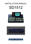
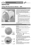
The assembled UKRAA VLF Receiver
The UKRAA VLF Receiver is designed to record Sudden Ionospheric Disturbances (SIDs)
induced by solar flares. It does this by monitoring transmissions from Earth-based beacons,
which are affected by changes in the ionosphere, giving an indirect indication of events on
the Sun. The main motivation for this work is to correlate these radio observations of solar
activity with those from optical observers, and to follow the cycles of sunspots as they
appear on the Sun.
The VLF Receiver User Manual explains how the unit may be connected to a variety of data
loggers, and to the UKRAA Starbase networked observatory. Please visit www.ukraa.com for
more information on how to share your observations with others.
Issue 1 2010 January
3
© UKRAA
Assembly Instructions
The following assembly instructions should be followed carefully. The VLF Receiver is not a
simple electronic assembly, and is not regarded as a project suitable for a beginner. If you
follow the instructions carefully you should be successful in building a VLF Receiver that
works. If you are not careful, you run the risk of having a problem that may be very difficult
to locate and fix later. If you are in doubt about your abilities, you are advised to seek out a
local electronic hobbyist or Radio Amateur with constructional experience.
It is recommended that you read these instructions right through before commencing on the
construction of the kit. You may need to prepare for some of the ideas suggested later in the
text before you get too far into the construction. It is appreciated that experienced
constructors will have developed their own techniques, but we suggest you think carefully
before diverting from the sequence suggested.
Tools Required
•
Wire cutters
•
Needle-nose pliers
•
Soldering iron
(low-voltage (24V) iron preferred at least 15-25 watt, small tip, 25 to 40 watt is better)
•
Light duty resin core solder 22SWG or 0.8mm
•
Sponge
•
Magnifying glass
•
Solder sucker or solder wick
Kit Contents
•
Printed Circuit Board (PCB)
•
Bag A – Resistors
•
Bag B – Capacitors
•
Bag C – Semiconductors
•
Bag D – Connectors, sockets and miscellaneous hardware
Issue 1 2010 January
4
© UKRAA
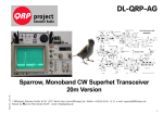
Printed Circuit Board (PCB)
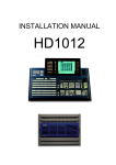
The photographs below show revision 5 of the VLF Receiver circuit board.
Component Side
Solder Side
All components are inserted from this side
Components are soldered on this side.
and soldered on the other side.
Assembly Sequence
The assembly instructions will follow the sequence below; full details are given in the later
sections:
•
Inspect the components supplied and check against the list in the Appendix
•
Install the Resistors and Capacitors (Bags A and B).
•
Install the dual in-line (DIL) sockets (Bag D)
•
Install the Semiconductors (Bag C)
•
Test the VLF Receiver.
Issue 1 2010 January
5
© UKRAA
The intention of the recommended assembly sequence is to install components in order of
height above the board surface.
•
Resistors, diodes and not electrolytic capacitors
•
DIL IC sockets
•
Polarised header plugs and pin clusters for jumpers
•
Electrolytic capacitors
(remember the polarity is important and the longer wire is the positive lead)
•
The variable resistors (trimpots)
(mount with the adjuster screws to the rear (D-25 end) of the board)
•
Install the regulators and transistors last and then test before installing the ICs
Pre-installed Components
The surface-mounted temperature sensor chip (IC7) has been pre-installed on the
component side of the PCB.
Install the Resistors
Remove the fixed resistors from Bag A.
Fixed resistor
The resistors have the values written on each plastic bag. If in doubt the value of resistors is
given by the colour-coded bands, see the section at the end if you are unfamiliar with
resistor colour codes. The resistors supplied are all five-band, 1% tolerance.
It is suggested that the variable resistors ('trimpots') (VR1...4) should be installed later after
the small ceramic capacitors have been soldered in. Resistor locations are marked on the
component side of the PCB with the symbol R followed by a number: R1, R2 etc.
Issue 1 2010 January
6
© UKRAA
The following table indicates the values of the resistors:
Identification
Quantity
R1, R2, R5, R6, R7, R8, R9, R10, R12, R16, R19, R20,
Resistance
19
10k
R3, R17
2
1M
R4
1
1k
R11, R18, R21, R22
4
100k
R13
1
8.2k
R14, R15
2
47k
R23, R24, R25, R26, R27, R28, R29
To prepare a resistor for insertion into the PCB, bend the two leads so that they form a right
angle to the resistor body, the wire spacing allowed for insertion is 0.3in.
Bending resistor wires prior to insertion.
Do not bend the leads close to the body of any component because it may damage the lead
anchorage.
To install, place the leads of the resistor through the appropriate holes and press the
resistor down against the component side of the PCB. There is no required orientation for
resistors - either lead may be inserted in either hole.
Turn the board over while holding the resistor in position and bend the leads slightly
outward to hold the resistor in place and solder the leads to the circuit side. You may find it
convenient to insert all the resistors with the same value first, and then move onto the next
value. This avoids errors due to a wrong resistor being installed and also avoids having to
continually refer to the colour code charts (in an Appendix), which can be hard on the eyes,
once the resistors are removed from the bandolier tape.
Issue 1 2010 January
7
© UKRAA
Several resistors may be loaded at the same time and retained by splaying the leads slightly
where they come though the PCB. They can then all be soldered at the same time. See the
section below describing how to make a simple assembly frame. It is suggested that you use
the component list as a guide and “cross-off” the resistor as you locate its correct position
and mount it. It may be useful to do the same on the layout diagram. It then soon becomes
clear which components you have yet to install, and makes locating their position much
easier.
Install the Capacitors
Remove the Capacitors from Bag B.
Identification
Quantity
Capacitance Value
C12
1
1nF Ceramic disc
C4,C5
2
1n5 1% Polystyrene
C3,C13
2
10nF Ceramic disc
C1,C2,C8,C14,C15,C16,C18,C19
8
100nF Ceramic multilayer
C7, C10
2
10uF 25V Electrolytic
C6,C11
2
100uF 25V Electrolytic
C9
1
220uF 35V Electrolytic
C17
1
4u7 63V Electrolytic
A selection of Capacitors
The 1nF disc capacitors are labelled '102', the 10nF labelled '103', and the 100nF labelled
'104'. You may need the magnifying glass to read these numbers!
Install the ceramic capacitors using the same technique as for the resistors. It is easiest to
install the shorter components first, leaving the tall components until later in the sequence.
Issue 1 2010 January
8
© UKRAA
Thus fit the electrolytic capacitors last. Once again it is suggested that one type and value is
selected and all these are installed, before moving on to a different value. Only the
electrolytic capacitors have a polarity that must be observed, and the PCB will be marked
with a “+” to indicate the correct orientation. Where there is no fixed orientation it is usual to
choose an orientation for the capacitors that allows their value to be easily read when
installed.
Now install the taller electrolytic capacitors observing the polarity marking on the board. The
longer of the two leads is the positive lead, but there is also a grey band up the sleeve with a
“-“ on the side nearest to the negative lead.
Miscellaneous
Variable Resistors
Variable resistor (multi-turn)
The components supplied do not have offset wires so unlike the one pictured can be
installed in reverse. This will affect the tuning direction of the adjustment screw. If the
adjusting screw is located so it is towards the rear of the board (the 25way connector P4) it
should be in the correct orientation.
Sockets
It is suggested you next install the sockets (Bag D). Take care to install the IC sockets the
right way round, since the orientation mark on the socket will serve as a reference to the
correct orientation for the insertion of the IC.
Issue 1 2010 January
9
© UKRAA
Semiconductors
Remove the Semiconductors from Bag C.
Be careful with the orientation of IC6, the double line in the screen-print signifies the
metallic “back”. Similarly ensure that the flats on IC8 and on T1 and T2 align with the
screen-print outline. When installing diodes and transistors it is essential that the correct
orientation be followed. The diodes with their axial leads look very like resistors but the
band on one end of the body indicates the negative (cathode)end and must align with the
screen-print on the PCB. Where glass-body diodes have been provided do not bend the
leads whilst holding the diode body. The lead should be held with a pair of fine-nose pliers
close to the body to prevent the stress of the bending fracturing the glass.
Identification
Quantity
IC1
1
TL084 amplifier
IC2
1
LM324N amplifier
IC3
1
24LC512/P EEPROM
IC4
1
ICL7662 regulator
IC6
1
+12V regulator, 7812
IC7
1
LM73 Temperature Sensor (pre-installed)
IC8
1
+5V regulator, 78L05
T1
1
BC547 transistor
T2
1
BF244A JFET
D1, D2, D3
3
1N914 diode
D4
1
1N4004 diode
Note that IC5, the MAX186 Analogue to Digital Converter, is an optional component which
may be fitted if Radio Sky Pipe compatibility is required.
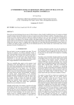
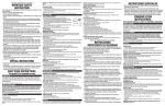
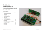
The image below shows the orientation of the LM73 temperature sensor, for your reference.
Pin 1 is underneath the 'T' of the underlined legend 'T731'.
Orientation of LM73
Issue 1 2010 January
10
© UKRAA
Hardware
Some of the header plugs on the board are polarised and the solid line on the screen print
signifies the position of the raised polarising peg.
WARNING! The earlier releases of the PCB have errors in the screen printing
in that the positions of some of the polarising pegs are not marked. This
does not apply to revision 5 and later.
Two pairs of crimp terminals are provided for wiring the connector to the polarised (white)
two-pin header plugs. Bare some insulated connecting wire and gently close the tangs on
the wire with the pliers. The bared wire length should be cropped so that the outer tangs
grip the insulation whilst the ones nearest the socket grip in the wire. The end of the wire
should not protrude more than 1mm beyond the lower crimp or it will impede the insertion
of the header pin. Since it is unlikely you will have the correct crimp tool you should run a
small amount of solder into the wire crimp to ensure a good connection. The crimp-socket is
then inserted into the shell. But you need to be careful to align the tongue with the slot in
the moulded shell. When aligned correctly push the crimp into the shell until the tongue
engages and the wire cannot be pulled out. A damaged wire may be replaced by gently
pushing the tongue in through the slot in the shell, whilst applying a gentle pull to the wire.
You may require a new crimp, though with care they can be re-soldered.
The interconnections are covered in the main manual.
A selection of Hardware
Identification
Quantity
IC1, IC2
2
14 pin socket
IC3, IC4
2
8 pin socket
IC5
1
20 pin IC socket
P1, P7, P9, P10
4
2 way plug & socket (pairs)
P2, P3
2
2 way terminal block
P5, P6 (2), P11, DC GAIN,
6
3 way header & links
P13
Issue 1 2010 January
11
© UKRAA
Testing
Visual Inspection
•
Start with a completed PCB with no ICs installed.
•
Check that the appearance of all soldered joints is satisfactory, and there are no
wires or pins that have been missed. A correctly made joint should reveal the end of
the though-board wire or pin. This must not be hidden inside a spherical blob of
solder. Check for a wetting meniscus on the sides of the through-wire (see diagram).
•
Check all electrolytic capacitors and diodes are inserted the right way round. The
grey band with a black "-" denotes the negative lead. The band on the diodes should
match those shown on the layout diagram.
•
Check all the IC sockets are oriented correctly, with the indicator slot in the correct
orientation (see the layout diagram).
•
Check the orientation of the transistors T1 and T2, and IC6 (note the position of the
"flat" on the moulding).
•
Place jumpers on the "OUT" side of P11 and the "X1" side of the "DC GAIN" header
pins. A further jumper may be placed on the "PROTECT" side of header P5.
Resistance Tests
It is suggested that any general purpose Digital Multimeter (DMM) can be used for the
following tests.
•
Measure the resistance between the wire-clamping. screws of P2. The initial reading
should be at or above 10kOhm and should drift slowly upwards to around 90kOhm
or higher as the large electrolytic capacitor charges up. Ideally your positive probe
should be on the screw nearest to IC5, to ensure the electrolytic capacitor charges
with the correct polarity. If the reading is below 5kOhm repeat the visual inspection
looking for stray wires or solder splashes between pads.
Issue 1 2010 January
12
© UKRAA
Power-up Tests
•
Assuming the results of the above tests are satisfactory, insert the ICs taking care to
orientate them correctly with regard to the indent on the socket. Check carefully
down the side of the IC sockets (magnifying glass) after insertion to ensure that all
the IC pins have entered the socket and there are none bent up underneath the
package.
•
Arrange a 15 Volt DC power source and connect to P2, but connecting the DMM in
series with the positive lead to the positive terminal of P2, and select direct current
measurement on the 200mA range on the DMM. Apply power and check that the
current draw is around 30mA. If the reading is above 50mA or very low remove the
power and return to visual inspection of the PCB.
•
If the current draw is correct remove the power and disconnect the DMM. Ensure that
VR4 is wound fully anti-clockwise (wind 15 turns to be sure, there is no end-stop).
Re-connect the DMM to read the output level on P10. Place a short across the aerial
terminals P1. Re-connect the power leads direct to P2 and apply power. The output
level should read about 0.2 to 0.25 Volts (on a PCB with a strap at R29....2.5 Volt
range setting.) It the reading is higher or much lower there may be a problem.
Remove the power, and repeat the preliminary tests before proceeding with detailed
fault-finding.
Proceed to the "Tuning" stage. This becomes part of the testing because successful tuning
indicates correct operation of the unit.
Soldering Guide
Technique
IMPORTANT:
DO NOT leave a soldering iron plugged in for a long time without using it.
NEVER leave a hot soldering iron unattended.
•
Clean the tip of the iron by wiping it on the damp sponge. It should be “tinned” with a
very thin coating of solder. The sponge will remove excess and any “slag”.
•
Place a small amount of solder on the tip, this should NOT form a big blob and is
NOT for making the joint but will help to convey the heat of the iron to the joint.
•
Hold soldering iron firmly down against the copper track and against the side of the
component lead so that the track and component lead are BOTH heated (about two
seconds) .
Issue 1 2010 January
13
© UKRAA
•
After the lead and the contact have heated, apply the solder to the lead and copper
track (NOT directly to the iron) until the solder melts and flows around the lead and
into the contact.
•
Remove the iron. This should leave a gently dished meniscus like water in a glass
showing that the solder has “wetted” the joint and thus made good electrical contact.
A lumpy or “crystalline” look to the joint suggests that the joint is “dry” and will not
make a reliable electrical contact. In such case it should be carefully reheated with
the iron and perhaps a very small about of solder until the required meniscus is
formed. The inability to form this meniscus easily suggests that the iron may not be
hot enough, or possibly is not “tinned” properly. Do not apply so much solder that it
runs across the PCB surface.
•
Allow the joint to cool and inspect the joint.
•
Trim the excess lead wire just above the solder joint.
•
If too much solder has been fed into the joint, and it resembles a blob, the excess
may be removed with the solder-wick or solder-sucker. The joint can then be
inspected for correct wetting under a magnifying glass.
Some Further Advice
It is recommended that you install the resistors first, the easiest way is to take a bag which
will contain the same value resistors (you may wish to check the colour code against the
table at the rear of the manual) select one and identify on the PCB, the position to
corresponding to the first resistor identity on the bag label e.g. R1 and after dressing the
leads, install in the appropriate holes. Be careful correctly identifying such as R6 and R8 and
R 16 and R18.
Multi-pin components can easily not to fitted snug to the board, because to slip out slightly
when the board is turned over for soldering. If you do not use a jig (see a later section for a
description of a simple aid) solder just one pin the inspect the top side of the board to see
the component it fully home against the board surface. The polarised header plugs are easy
to mount slightly skewed, but correct neat assembly will enhance your satisfaction with the
finished unit. If you use the foam aid to hold the components, it is suggested you place a
jumper on the unpolarised jumper pins or they just perforate the foam and are not held
tight.
It is possible that some components maybe supplied due to ordering difficulties with slightly
different lead spacing specification. The lead spacing can be altered carefully with a pair of
narrow-nose pliers. Try not to bend lead too close to the components body because it is
possible to damage the component. The most sensitive to this form of damage are the glass
encapsulated diodes. The wires should not be bent closer than about 2mm to the body of
the component to prevent fracturing the the lead-to-glass seal.
Issue 1 2010 January
14
© UKRAA
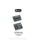
Examples of Soldered Joints
Making good soldered joints is vital to the correct operation of this unit. The pictures below
provide a guide to help you inspect your work and correctly assess the solder quality.
The joint should look like this:
Issue 1 2010 January
15
© UKRAA
A good soldered joint
A bad joint looks like this.
Issue 1 2010 January
16
© UKRAA
Simple Assembly Frame
The insertion of wire-ended components is fairly straight-forward in that they can be
retained in position, whilst turning the board for soldering, by splaying the excess leads out.
Other components, like headers, and sockets, with more solid connections are more difficult.
Professional assemblers use a frame, which allows all the components to be inserted and
held on position against the PCB by a foam block whilst the frame is rotated to offer up the
solder side of the board. A very simple version of this may be easily made with some foam, a
piece of thick cardboard, or hardboard, and a couple of elastic bands. The only caution is
that the pins of the headers may get hot during soldering and some foam may melt at quite
low temperatures. The easy way to avoid problems like this is to insert the jumper on the
component side of the header pins before strapping the foam over them. Using this method
you can insert several components and solder them in position secure in the knowledge that
they will stay properly seated against the board. Just be careful not to touch the elastic
bands with the soldering iron or everything may fly apart!
Soldering Assembly Frame
Soldering Assembly Frame (side view)
Issue 1 2010 January
17
© UKRAA
Cleaning the Circuit Board
You may wish to remove any solder flux residues left after soldering. There are products
available for this purpose, as liquids or aerosols. Depending on the solder you have used, it
may also be possible to use water as the solvent, alternatively cellulose thinners can be used
for a faster effect. Scrubbing with a stiff brush (even an old toothbrush) may be all that is
required.
Correcting Mistakes
If you have to remove a faulty or misplaced through-hole component, remember the PCB is
worth more than the component. Chop up the component usually through the body, to leave
as long a lead as possible and enable you to remove the leads individually. This can be done
usually without getting the board too hot for the through-hole to be damaged. However,
this often leaves you with a solder filled hole. There are all kinds of solder suckers, but these
can be difficult to use particularly on ground-plane holes and sometimes difficult to keep
tinned and keep the joint hot enough. The following technique can be successful if done
carefully.
Work on the component side of the board. Since you pulled the legs out that way you should
have a dome of solder on that side whereas the solder surface in the hole on the other side
may be below the board surface. A fairly large chisel bit is best for the following operation
rather than a conical point.
Take some solder-braid (use good quality Multicore) if you are right-handed place the reel
or the slack on the right of the PCB and hold the end in your left hand. Place the last used
part of the braid, yes that bit filled with solder, over the hole to be cleared, fill the soldering
iron bit with a blob of of new solder and place it on top of the braid and over the hole. When
you see the solder start to flow pull the braid away across the hole under the iron keeping
the iron over the hole. The solder should "wick out" of the hole and fill the braid as you move
it away. Stop pulling when no more solder enters the braid and quickly remove the iron.
When you remove the braid and iron you should now see a clear hole.
The secret is to use plenty of new solder to engulf the old solder in a pool that you then
draw into the new wick. The new wick appearing over the hole tends to keep it cooler as
well. If you work from the component side of the board there is less chance of damaging
tracks if you do get things too hot. If it doesn’t work first time allow the hole to cool for a bit
before trying again. Be careful when using the hole again and inserting a component -
remember it is slightly smaller than original because there will be a thin film of solder over
the inside. If you do damage the pad on the component side it does not matter too much
because the connection will be made on the solder side of the board and it can easily be
patched if necessary.
Issue 1 2010 January
18
© UKRAA
Appendix 1 - Component List
Identification
Qty
Component
R28, R29
19
10k
R3, R17
2
1M
R4
1
1k
R11, R18, R21, R22
4
100k
R13
1
8.2k
R14, R15
2
47k
VR1,VR2,VR3
3
10k 10 turn variable resistor
C12
1
1nF Ceramic disc
C4,C5
2
1n5 1% Polystyrene
C3,C13
2
10nF Ceramic disc
C1,C2,C8,C14,C15,C16,C18,C19
8
100nF Ceramic multilayer
C7, C10
2
10uF 25V Electrolytic
C6,C11
2
100uF 25V Electrolytic
C9
1
220uF 35V Electrolytic
C17
1
4u7 63V Electrolytic
Bag A
R1, R2, R5, R6, R7, R8, R9, R10, R12,
R16, R19, R20, R23, R24, R25, R26, R27,
Bag B
Issue 1 2010 January
19
© UKRAA
Bag C
IC1
1
TL084 amplifier
IC2
1
LM324N amplifier
IC3
1
24LC512/P EEPROM
IC4
1
ICL7662 regulator
IC6
1
+12V regulator, 7812
IC7
1
LM73 Temperature Sensor (pre-installed)
IC8
1
+5V regulator, 78L05
T1
1
BC547 transistor
T2
1
BF244A JFET
D1, D2, D3
3
1N914 diode
D4
1
1N4004 diode
IC1, IC2
2
14 pin socket
IC3, IC4
2
8 pin socket
IC5
1
20 pin IC socket
P1, P7, P9, P10
4
2 way plug & socket (pairs)
P2, P3
2
2 way terminal block
P5, P6 (2), P11, DC GAIN
5
3 way header & links
Bag D
Issue 1 2010 January
20
© UKRAA
Appendix 2 – Resistor Colour Codes
Resistor Colour Code Chart
Issue 1 2010 January
21
© UKRAA
The following table indicates the values of the resistors:
Colour Code
Quantity
Resistance
19
10k
R3, R17
2
1M
R4
1
1k
R11, R18, R21, R22
4
100k
R13
1
8.2k
Grey, Red, Black, Brown
R14, R15
2
47k
Yellow, Violet, Black, Red
Identification
R1, R2, R5, R6, R7, R8, R9, R10, R12,
R16, R19, R20, R23, R24, R25, R26,
First 4 colours
Brown, Black, Black, Red
R27, R28, R29
Brown, Black, Black,
Yellow
Brown, Black, Black,
Brown
Brown, Black, Black,
Orange
Note that the colours are always read with the first colour nearest the edge of the
component as shown above. This is not easy to determine with the resistors supplied but
they are all five-band 1% tolerance so will all have a brown ring at one end. Sometime it will
be necessary to use the resistance range of your multi-meter to gain confidence you have
the right value.
Issue 1 2010 January
22
© UKRAA
Appendix 3 – VLF Receiver PCB Layout
VLF Receiver Component Overlay
Issue 1 2010 January
23
© UKRAA
Appendix 4 – VLF Receiver Circuit Diagram
Issue 1 2010 January
24
© UKRAA
Appendix 5 – Regulatory Compliance
RoHS
The Directive on the restriction of the use of certain hazardous substances in electrical and
electronic equipment 2002/95/EC, (commonly referred to as the Restriction of Hazardous
Substances Directive or RoHS) was adopted in February 2003 by the European Union. The
RoHS directive took effect on 2006 July 1, and is required to be enforced and become law in
each member state. This directive restricts the use of six hazardous materials in the
manufacture of various types of electronic and electrical equipment. In speech, RoHS is often
spelled out, or pronounced “rosh”.
The above paragraph was taken from the Wikipedia essay on RoHS.
The RoHS Directive restricts the use of the following six hazardous substances in electronic
and electrical equipment products falling within the Directive:
1. Lead
2. Mercury
3. Cadmium
4. Hexavalent chromium
5. Polybrominated biphenyls
6. Polybrominated diphenyl ethers
UKRAA confirms that the suppliers of the components and materials used in the UKRAA VLF
Receiver have stated that such components and materials are RoHS compliant and that
reasonable steps have been taken to confirm these statements.
WEEE
RoHS is closely linked with the Waste Electrical and Electronic Equipment Directive (WEEE)
2002/96/EC that sets collection, recycling and recovery targets for electrical goods and is
part of a legislative initiative to solve the problem of huge amounts of toxic e-waste.
The Waste Electrical and Electronic Equipment (WEEE) Directive is designed to ensure the
efficient collection and recycling of electrical and electronic equipment at end-of-life. If a
customer purchases a new product from UKRAA which falls within the WEEE Directive to
replace an existing one (of similar function to the one that has been sold) and intends to
dispose of the existing one, then the customer can request that we take back the existing
product and deal with the costs and logistics of recycling it. Any customer wishing to take
advantage of this facility should contact us. Provided that the existing product comes within
the scope of the WEEE Directive, we will make arrangements for its return or collection and
will deal with its disposal.
Issue 1 2010 January
25
© UKRAA
Contacts
The UK Radio Astronomy Association
Springfield
Rookery Hill
Ashtead Park
Ashtead
Surrey
KT21 1HY
A Company limited by Guarantee. Registered in England No. 6481611.
Registered Charity in England and Wales No. 1123866.
E-mail: [email protected]
Website: www.ukraa.com
Fax: 0870 132 3728
Telephone: 01372 279066
Starbase Information
Website: www.starbase.org
BAA Radio Astronomy Group
Website: www.britastro.org/radio
Issue 1 2010 January
26
© UKRAA
Revision History
Revision Date
Author
Status
Draft A
2009-08-08 A J Melia
Internal draft for peer review
Draft B
2009-08-09 L M Newell
Incorporated reviewer's comments
Draft C
2009-08-11 L M Newell
Incorporated reviewer's comments
Draft D
2009-08-20 L M Newell
Internal draft for peer review
Issue 1
2010-01-12 L M Newell
Incorporated reviewer's comments
Outstanding Work
Update component list for release 005 of the PCB
Limited by Guarantee Reg. No. 6481611
Registered UK Charity No. 1123866
Issue 1 2010 January
27
© UKRAA