Download INSTALLATION MANUAL - Discovery Resources
Transcript
INSTALLATION MANUAL www.snellwilcox.com HD1012 Installation Manual for V3 Software Issue 1, Revision 1, September 2003 © 1998-2003 Snell & Wilcox Post Production Division The Business and Technology Centre Shire Hill SAFFRON WALDEN Essex, CB11 3AQ U.K. Tel: Fax: Web: + 44 (0) 1799 523817 + 44 (0) 1799 528081 http://www.snellwilcox.com Customer Care Tel: Fax: E-mail: Ftp: + 44 (0) 1799 508100 + 44 (0) 1799 508800 [email protected] ftp://ftp.snellwilcox.com/post_production COPYRIGHT Copyright protection claimed includes all forms and matters of copyrightable material and information now allowed by statutory or judicial law or hereinafter granted, including without limitation, material generated from the software programs which are displayed on the screen such as icons, screen display looks etc. Information in this manual and software are subject to change without notice and does not represent a commitment on the part of Snell & Wilcox Ltd. The software described in this manual is furnished under a license agreement and may not be reproduced or copied in any manner without prior agreement with Snell & Wilcox Ltd. or their authorized agents. Reproduction or disassembly of embedded computer programs or algorithms prohibited. No part of this publication may be transmitted or reproduced in any form or by any means, electronic or mechanical, including photocopy, recording or any information storage and retrieval system, without permission being granted, in writing, by the publishers or their authorized agents. Page ii HD1012 Installation Manual – V3, Issue 1, Rev 1 S&W Production & Post Production www.snellwilcox.com SAFETY Explanation of Safety Symbols This symbol refers the user to important information contained in the accompanying literature. Refer to users manual. This symbol indicates that hazardous voltages are present inside. No user serviceable parts inside. This unit should only be serviced by trained personnel. Safety Warnings Servicing instructions, where given, are for use by qualified personnel only. To reduce risk of electric shock do not perform any actions on this equipment other than contained in the operating instructions, unless you are qualified to do so. Refer all servicing to qualified personnel. WARNING TO REDUCE THE RISK OF ELECTRIC SHOCK, DO NOT EXPOSE THIS APPLIANCE TO RAIN OR MOISTURE. ? Always ensure that the unit is properly earthed and power connections correctly made. ? This equipment must be supplied from a power system providing a PROTECTIVE EARTH connection and having a neutral connection which can be reliably identified. ? The power outlet supplying power to the unit should be close to the unit and easily accessible Power Supply and Connections Mains Supply Voltage Before connecting the equipment, observe the safety warnings section and ensure that the local mains supply is within the rating stated on the rear of the equipment. The HD1012 systems have power supplies that are suitable for voltages of 115V (+6% -10%) and 230V (+/-10%) @ 50 and 60Hz. S&W Production & Post Production HD1012 Installation Manual – V3, Issue 1, Rev 1 Page iii www.snellwilcox.com Power cable supplied for the USA The equipment is shipped with a power cord with a standard IEC molded free socket on one end and a standard 3-pin plug on the other. If you are required to remove the molded mains supply plug, dispose of the plug immediately in a safe manner. The color code for the lead is as follows: GREEN lead connected to E (Protective Earth Conductor) WHITE lead connected to N (Neutral Conductor) BLACK lead connected to L (Live Conductor) Power cable supplied for countries other than the USA The equipment is shipped with a power cable with a standard IEC moulded free socket on one end and a standard IEC moulded plug on the other. If you are required to remove the moulded mains supply plug, dispose of the plug immediately and safely. The colour code for the lead is as follows: GREEN/YELLOW lead connected to E (Protective Earth Conductor) BLUE lead connected to N (Neutral Conductor) BROWN lead connected to L (Live Conductor) Free Plug Free Socket Control Panel Power cable tie If this facility is used allow enough cable after the tie to allow the power plug to be easily removed from and inserted into the power socket. Min length after tie = 20mm I A cable tie mount is located by the power inlet on the control panel. A cable tie may be used to fix the power cable to the unit to prevent accidental disconnection of power. O Cable tie Cable tie mount Battery Warnings Lithium Battery- There is a Lithium battery on the VME card which is mounted “piggy-back” on the Mainframe CPU card. If this battery is incorrectly replaced there is a danger of explosion! Ensure that the same make and model of battery is used if replacement is required (a manufacturer recommended equivalent may be used if the original type is not available). Empty Holder - There is an empty battery holder on the MBX card in the Control Panel, this holder is not used. No battery should be fitted to this card! Page iv HD1012 Installation Manual – V3, Issue 1, Rev 1 S&W Production & Post Production www.snellwilcox.com Maintenance & Repair There are no user serviceable parts within either the Mainframe or the Control Panel. In the unlikely event of an equipment failure contact the Snell & Wilcox Post Production Customer Support department, contact details below: Telephone + 44 (0) 1799 508100 or + 44 (0) 1799 508300 Fax + 44 (0) 1799 508800 e-mail [email protected] Cooling Fan Failure IF THE COOLING FANS AT THE REAR OF THE SD1000 SWITCHER MAINFRAME SHOULD STOP FOR ANY REASON, THEN THE SYSTEM SHOULD BE SWITCHED OFF IMMEDIATELY OR PERMANENT DAMAGE MAY RESULT. Depending on the length of time the mainframe has been run with no fan the unit may need to be returned for checking and repair. Contact Snell and Wilcox or your Snell and Wilcox dealer to discuss the situation. Safety Standards This equipment complies with the following standards: BS EN60950 (2000) Safety of information Technology Equipment Including Electrical Business Equipment. UL1419 (1997) Standard for Safety – Professional Video and Audio equipment, S&W Production & Post Production HD1012 Installation Manual – V3, Issue 1, Rev 1 Page v www.snellwilcox.com EMC Standards This unit conforms to the following standards: BS EN 55103-1 : 1997 Electromagnetic Compatibility, Product family standard for audio, video, audio-visual and entertainment lighting control apparatus for professional use. Part 1. Emission BS EN 55103-2 : 1997 Electromagnetic Compatibility, Product family standard for audio, video, audio-visual and entertainment lighting control apparatus for professional use. Part 2. Immunity Federal Communications Commission Rules Part 15, Class A :1998 EMC Environment The product(s) described in this manual conform to the EMC requirements for, and are intended for use in, either The commercial and light industrial environment (including, for example, theatres) E2 or The controlled EMC environment (e.g., purpose-built broadcasting or recording studios), and the rural outdoor environment (far away from railways, transmitters, overhead power lines, etc.) E4 EMC Performance of Cables and Connectors Snell & Wilcox products are designed to meet or exceed the requirements of the appropriate European EMC standards. In order to achieve this performance in real installations it is essential to use cables and connectors with good EMC characteristics. All signal connections (including remote control connections) shall be made with screened cables terminated in connectors having a metal shell. The cable screen shall have a large-area contact with the metal shell. COAXIAL CABLES Coaxial cables connections (particularly serial digital video connections) shall be made with high-quality double-screened coaxial cables such as Belden 8281 or BBC type PSF1/2M. D-TYPE CONNECTORS D-type connectors shall have metal shells making good RF contact with the cable screen. Connectors having "dimples" which improve the contact between the plug and socket shells, are recommended. Page vi HD1012 Installation Manual – V3, Issue 1, Rev 1 S&W Production & Post Production www.snellwilcox.com CONTENTS SECTION A - INSTALLATION ........................................................................................... 1 INTRODUCTION ......................................................................................................................... ON DELIVERY OF THE SYSTEM ............................................................................................... LOCATION AND ENVIRONMENT ............................................................................................... Control Panel Installation .................................................................................................... Battery ................................................................................................................................ Power Supplies .................................................................................................................. SYSTEM INTERCONNECTION ................................................................................................... Introduction ......................................................................................................................... Control Panel ...................................................................................................................... Connecting to an Alternate Mainframe .............................................................................. Power ................................................................................................................................. Button Bus Multi Control ............................................................................……………….. Inputs ................................................................................................................................. Outputs ............................................................................................................................... Muliple Monitor Mode ......................................................................................................... REFERENCING ......................................................................................................................…... Referencing - System Delays ......................................................................................... CONTROL PORTS AND PROTOCOLS ....................................................................................... Ports ................................................................................................................................... FTP - Connecting to a PC .................................................................................................. GVG 100 ............................................................................................................................ GVG 4000 ........................................................................................................................... Sony DVS ........................................................................................................................... Using a Sony BVE-9100 Editor .......................................................................................... VTR ..................................................................................................................................... Follow Real VTR ................................................................................................................. S & W Tally ......................................................................................................................... Aux ..................................................................................................................................... Probel TX320 & DVE .......................................................................................................... BBC Camera ...................................................................................................................... Button Bus ......................................................................................................................... P-Bus .................................................................................................................................. Router Protocols ................................................................................................................ General Purpose Inputs & Outputs .................................................................................... The Inputs ................................................................................................................. The Outputs ............................................................................................................. Programming the Inputs .......................................................................................... Programming the Outputs ........................................................................................ Multiple Conditions ................................................................................................... List of GPO Occurences .......................................................................................... OTHER INSTALLATION PROCEDURES ................................................................................... Setting the Real-Time Clock ............................................................................................. System Reboot .................................................................................................................. Remote Allocation of Aux Sources .................................................................................... CONNECTOR PINOUTS ............................................................................................................. Mainframe RS-422 ............................................................................................................ Mainframe RS-232 .............................................................................................................. GPIs & GPOs ..................................................................................................................... Control Panel to LCD ......................................................................................................... SYSTEM WITH INTEGRATED ROUTER .................................................................................... 2 2 3 3 3 4 5 5 5 5 5 6 10 10 11 12 13 14 14 14 14 15 16 18 20 20 21 21 21 21 21 21 21 22 22 23 24 25 26 27 28 28 28 29 34 34 34 35 36 38 SECTION B - SPECIFICATIONS ....................................................................................... 41 S&W Production & Post Production HD1012 Installation Manual – V3, Issue 1, Rev 1 Page vii www.snellwilcox.com LIST OF DIAGRAMS Wiring of IEC mains inlet connectors ................................................................... 4 Control Panel - Rear View.................................................................................... 7 Control Panels’ Top Connector Plate ................................................................... 7 Control Panel Dimensions.................................................................................... 8 Switcher Mainframe Rear Panel........................................................................... 9 System Connection Diagram .......................................................................……. 10 Multi-Monitor Mode Connections ......................................................................... 11 Pro-Bel Panel Button Functions ........................................................................... 29 Quartz Panel Button Functions ............................................................................ 30 Diode Buffer ........................................................................................................ 32 Aux Control Interconnections ..........................................................................…. 33 Integrated Router Connections ............................................................................ 39 LIST OF TABLES Line Standard Timing Information...................................................................….. 12 System Delay Timings ......................................................................................... 13 GVG 4000 Crosspoints ........................................................................................ 15 GVG 4000 bus assignments ................................................................................ 16 Sony DVS bus assignments................................................................................. 16 Sony DVS Crosspoints ........................................................................................ 17 Follow Real VTR connector pinouts ..................................................................... 20 Router Protocols ......................................................................................……… 21 GPI Function Mapping.......................................................................................... 24 Mainframe RS-232/422 Connector Pinouts.......................................................... 34 GPI/P Connector Pinout ............................................................................…….. 35 Control Panel to LCD Wiring ............................................................................... 36 Page viii HD1012 Installation Manual – V3, Issue 1, Rev 1 S&W Production & Post Production www.snellwilcox.com SECTION A INSTALLATION S&W Production & Post Production HD1012 Installation Manual – V3, Issue 1, Rev 1 Page 1 www.snellwilcox.com INTRODUCTION These installation instructions provide a guide to the installation of the HD1012 High-Definition Switchers. ON DELIVERY OF THE SYSTEM The equipment is supplied in dedicated packaging provided by the manufacturer and should not be accepted if delivered in inferior or unauthorised materials. 1. Carefully unpack the system components and check them against the packing list. If there is anything incorrect, notify your dealer or Snell and Wilcox directly at once. 2. Check that the equipment has not been damaged in transit. If any damage has occurred, notify your dealer or Snell and Wilcox directly at once as well as the carrier. 3. Always retain the original packing materials if possible, they could prove useful should it ever be necessary to transport or ship the system units. The system components are: 1. HD1000 Switcher Mainframe 2. CP1512 Control Panel 3. CP1512 LCD Touch Screen module 4. 25-way D-type cable to link Control Panel and LCD Touch Screen module 5. 9-way D-type cable to link Control Panel and LCD Touch Screen module 6. 10 Base-T cable to link Control Panel and Switcher Mainframe 7. User manual. Page 2 HD1012 Installation Manual – V3, Issue 1, Rev 1 S&W Production & Post Production www.snellwilcox.com LOCATION AND ENVIRONMENT Environmental Considerations The ambient temperature for all the supplied equipment should not exceed the limits of 5 and 35 degrees C. at a relative humidity of 10 to 90% (non-condensing). Installing the equipment in a clean environment with moderate temperature and humidity will promote a long and trouble-free equipment life. Location The HD1000 may be used free-standing (table-top configuration) or installed in a standard 483mm (19 inch) equipment rack. The following precautions should be observed: a) The cooling fan exhausts at the rear of the unit must not be obstructed - a minimum clearance of 200mm (8 inches) is ESSENTIAL. b) The slots in the front panel are to allow the inlet of cooling air and MUST NOT BE OBSTRUCTED. c) When mounting the mainframe in an equipment rack it MUST be supported at the rear, not by the rack-mounting ears alone. Cooling is provided by drawing air in at the front of the unit and exhausting it at the rear. The mainframe should never be operated for any significant period of time with any covers removed as this will affect the internal airflow and cause overheating. Control Panel Installation The control panel is designed to stand freely on a tabletop. If it is necessary to secure the control panel to a control desk (e.g., in an OB van) the control panel has to be opened. This installation MUST be carried out by a qualified Installation or Service engineer. Battery WARNING There is a battery holder on the MBX card within the Control Panel which is not used. No battery should be fitted to this card S&W Production & Post Production HD1012 Installation Manual – V3, Issue 1, Rev 1 Page 3 www.snellwilcox.com LOCATION AND ENVIRONMENT - continued Power Supplies The Switcher Mainframe and/or Control Panel may be fitted with dual power supplies. In each case the unit will work happily with a single power-supply connected if required. For safety a mains earth connection MUST be provided. Control Panel The control panel is protected by a 4 amp anti-surge (slow-blow) fuse located in the mains inlet / power switch assembly, see diagram below. E E = Protective Earth Conductor N = Earthed Neutral Conductor L N Fuse L = Phase Conductor Switch Mainframe The mainframe is protected by an internal fuse that is not user replaceable. E = Protective Earth Conductor N = Earthed Neutral Conductor L = Phase Conductor Page 4 HD1012 Installation Manual – V3, Issue 1, Rev 1 S&W Production & Post Production www.snellwilcox.com SYSTEM INTERCONNECTION Introduction Your system has been set up and tested before shipment. Installation normally consists of siting and interconnecting the system components, connecting video and key inputs and outputs and setting up. Control Panel Remove and keep the supplied nuts and washers from the two bolts on the top of the Control Panel. Remove the LCD Touch Screen module from the packaging. Carefully fit it over the two bolts on the top of the Control Panel. Place the LCD Touch Screen’s earth strap over the nearest bolt, then fix down the LCD Touch Screen using the washers and nuts that you removed earlier. Connect the 25-pin D connector to the similar one on the rear of the Control Panel using the cable provided. Connect the 9-way D connector to the similar one on the rear of the Control Panel using the cable provided. If desired, a standard VGA monitor can be plugged into the 15-way sub-D connector at the bottom rear of the panel. The signal frequency is 39.06kHz Horizontal and 62.5Hz Vertical and should be acceptable to most (but not all) SVGA-compatible monitors. Finally, connect the 10 Base-T connector on the Control Panel to the socket on the Switcher Mainframe marked “Panel 10 BASE TX” using the cable provided. Connecting to an Alternate Mainframe The CP1524 Control Panel can be used to control another (Alternate) mainframe, e.g., a SD system. The IP address of the alternate mainframe is set in the Miscellaneous - IP Address menu. The alternate mainframe is connected to the primary mainframe via the 10 BASE T sockets. Connect the 10 BASE T socket on the rear panel of the mainframe (adjacent to the Panel 10 BASE TX connector) to the Panel 10 BASE TX socket on the alternate mainframe. Power Switch all power switches to their OFF states. Connect IEC power cables from the power socket(s) on the rear of the Switcher Mainframe and Control Panel to the appropriate AC mains distribution socket(s). The HD1000 mainframe has a shutdown switch for each power supply behind the front door on the left hand side. When the power supply is shut down, the red light in the shutdown button will illuminate. S&W Production & Post Production HD1012 Installation Manual – V3, Issue 1, Rev 1 Page 5 www.snellwilcox.com SYSTEM INTERCONNECTION - continued Button Bus Multi Control Button Bus Multi Control is a facility which allows one switcher control panel to control two switcher mainframes simultaneously, so, for example, a program can be produced in both HD and SD at the same time from one control panel. The basic Button Bus function is a RS422 protocol which outputs a serial code on a selected mainframe serial port when a key is pressed or released. By connecting two mainframes together this facility may be used to allow one control panel to control two mainframes simultaneously using the function “Button Bus Multi Control”. To use this facility ensure that both mainframes have the same set-up and are in the same operational situation otherwise problems will arise when using certain control buttons such as toggle functions. Set one of the serial ports on each of the two mainframes to “B Bus Multi Ctl” using the Config – System – Set Port Protocols. Connect these two ports together using a RS422 swap cable. With the system set-up as above any button presses, joystick movements or T-bar movements will control both mainframes simultaneously. Note Page 6 Button Bus Multi Control is an option that requires an enabling password. A password is available from Snell & Wilcox technical support. HD1012 Installation Manual – V3, Issue 1, Rev 1 S&W Production & Post Production www.snellwilcox.com SYSTEM INTERCONNECTION - continued DISPLAY 2 MAINFRAME 10 BASE T VGA SNELL & WILCOX MADE IN SAFFRO N WALDEN, ESSEX, UK. MODEL No. SERIAL No. RS232 DISPLAY 1 115/230 V 60/50 Hz 1.0/0.5 A T 5A 250V Control Panel - Rear View Control Panels’ Top Connector Plate S&W Production & Post Production HD1012 Installation Manual – V3, Issue 1, Rev 1 Page 7 
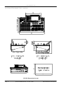
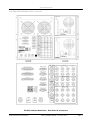
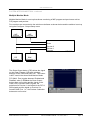
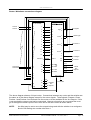
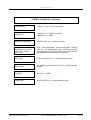
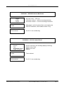
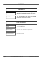
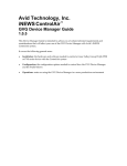
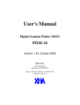
www.snellwilcox.com SYSTEM INTERCONNECTION - continued 819 824 CP1512 Dimensions in mm Page 8 HD1012 Installation Manual – V3, Issue 1, Rev 1 S&W Production & Post Production www.snellwilcox.com SYSTEM INTERCONNECTION - continued HD1000 Switcher Mainframe - Rear Panel & Connectors S&W Production & Post Production HD1012 Installation Manual – V3, Issue 1, Rev 1 Page 9 www.snellwilcox.com SYSTEM INTERCONNECTION - continued Inputs Connect up to 12 HD-SDI inputs to the 12 Serial Inputs of the Switcher Mainframe. Sources can be either video or key. Outputs Connect the Program, Clean Pgm, Preview 1, & Preview 2 outputs to external equipment or monitoring devices as desired. There are two copies of each output available. Program This is the main program output. Clean Pgm This is the main program output before the DSK stage. Preview 1 Preview 1 can be switched between any source, a number of mixing points in the system and transition previews. Preview 2 Preview 2 is a second preview output with similar capabilities to the first, except that it cannot preview mixer transitions. The Preview 1 output is also available in Analogue Component, as either YPbPr or RGB. Whether YPbPr or RGB format is used can be selected in the Configure - System - Genlock & Outputs menu. R, G, B and Y outputs have syncs. If the monitor requires separate syncs, the Ref Sync Output can be used if it is not required for system referencing. There are four Aux outputs for use as required. There are two copies of each output. Connection Diagram HD1000 Mainframe Inputs 1 Pgm 2 Clean 3 4 Pvw-1 5 Pvw-2 1 2 1 2 1 2 1 6 2 7 Y Pb Pr 8 Program Clean Program Preview 1 Preview 2 Analogue Preview 9 10 11 12 Ref 1 1a Aux 1 2 2a Aux 2 3 3a Aux 3 4 4a Aux 4 Loop Terminator Page 10 HD1012 Installation Manual – V3, Issue 1, Rev 1 S&W Production & Post Production www.snellwilcox.com SYSTEM INTERCONNECTION - continued Multiple Monitor Mode Multiple Monitor Mode is a set-up that allows monitoring of M/E program and preview as well as P/P program and preview. Four manitors are connected to the switcher mainframe as shown below and the switcher is set-up using the Configure - Output Setup menu. M/E Preview M/E Program Clean Preview 2 Preview 1 Program P/P Preview HD1000 DSK Program The Clean Output button (F2R) allows the signal on the Clean Program O/P to be switched between Clean, DSK and DSK Pvw. This button is NOT used in the above Multi Monitor Mode. F1R (Multi. Pvw) toggles between Enabled and Disabled, when in Enabled the Clean Output button does not function and the signal on the Clean O/P is forced to M/E Program, the selections for Preview 1 are limited to the P/P & DSK signals and the signal on Preview 2 is forced to M/E Pvw. I.e., the Preview 2 selection buttons do not function. S&W Production & Post Production HD1012 Installation Manual – V3, Issue 1, Rev 1 Page 11 www.snellwilcox.com SYSTEM TIMINGS Referencing The Switcher can be Genlocked to any of its 12 HD-SDI Inputs or to tri-level sync. on the Ref Analogue In loop-through connectors, selectable from the Configure-SystemGenlock & Outputs menu (see User Manual). Note that the input number set in this menu is absolute and is not remapped through the Configure-User-Source Mapping menu. If the incoming reference signal is not used elsewhere then the remaining Ref Analogue In BNC should be terminated with a 75? terminator. Whether the Switcher Mainframe is acting as the Master SPG for the system or is being Genlocked to an external source, the Ref Sync Out BNC provides an adjustably-timed analogue tri-level sync. output with which to synchronise external sources. Referencing - Input Timing To obtain correctly positioned pictures, all sources must be timed within a window that is 131072 74.25MHz or 74.25/1.001MHz clock periods wide. The table below shows how many milliseconds and lines this equals in the currently-supported line standards. Timing the sources can be achieved by adjusting (a) the Genlock H/V Phase controls (when the switcher is not the Master SPG), (b) the genlock controls of the source equipment, and/or (c) the Ref Sync Output’s Sync H/V-Phase controls. These controls can be found in the ConfigureSystem-Genlock & Outputs sub-menu, see User Manual Note: the Input and Output Line-Standards must be correctly set before doing this. Line Standard Timing Information Standard Name Total Lines Clocks/Line Total (Active) Clock Rate Timing Window Line Length 1035i 60Hz 1125 2200 (1920) 74.25MHz 59.57 lines; 1.765ms 29.63µs 1035i 59.94Hz 1125 2200 (1920) 74.25/1.001MHz 59.57 lines; 1.767ms 29.66µs 1080i 60Hz 1125 2200 (1920) 74.25MHz 59.57 lines; 1.765ms 29.63µs 1080i 59.94Hz 1125 2200 (1920) 74.25/1.001MHz 59.57 lines; 1.767ms 29.66µs 1080i 50Hz 1125 2640 (1920) 74.25MHz 49.65 lines; 1.765ms 35.55µs 1080p 30Hz sF 1125 2200 (1920) 74.25MHz 59.57 lines; 1.765ms 29.63µs 1080p 29.97Hz sF 1125 2200 (1920) 74.25/1.001MHz 59.57 lines; 1.767ms 29.66µs 1080p 25Hz sF 1125 2640 (1920) 74.25MHz 49.65 lines; 1.765ms 35.55µs 1080p 24Hz sF 1125 2750 (1920) 74.25MHz 47.66 lines; 1.765ms 37.04µs 1080p 23.976Hz sF 1125 2750 (1920) 74.25/1.001MHz 47.66 lines; 1.767ms 37.07µs 60Hz 750 1650 (1280) 74.25MHz 79.43 lines; 1.765ms 22.22µs 59.94Hz 750 1650 (1280) 74.25/1.001MHz 79.43 lines; 1.767ms 22.24µs 720p 720p Figures in the right-hand two columns are approximate. Page 12 HD1012 Installation Manual – V3, Issue 1, Rev 1 S&W Production & Post Production www.snellwilcox.com SYSTEM TIMINGS - continued Referencing - System Delays The total delay through the system depends partly on the current standard but mainly on which cards are fitted to the HD1000 mainframe. The minimum delays for each non-DVE card are shown below. The delay through the external HD1132 router (when fitted) is a few serial (1.485GHz) clocks and is therefore negligible. System Delay Timings Name Function Optional? Clocks Time (at 74.25MHz clock-rate) DES Deserialiser No 56 0.75421µs SRC Sources No 6 0.080808µs KEY Chroma Keyer Yes 137 1.8451µs CCR Color Corrector Yes 74 0.99663µs BDR Border Generator Yes 320 4.3098µs SWR Switcher No 99 1.3333µs CPU CPU & Outputs No 24 0.32323µs Total 716 9.6431µs The times above are calculated based on the standard 74.25MHz clock rate as used by most HD standards. For NTSC-timing-compatible standards such as 1080i/59.94Hz that use the 74.25/1.001MHz clock-rate, the times will be longer by one part in one thousand. Therefore with all options fitted, the minimum delay through the system is 716 clocks (9.6431µs), as shown above. With no options fitted, the minimum system delay is 56 + 6 + 99 + 24 = 185 clocks (2.4916µs); the BYPass card that replaces a non-fitted option card incurs no clocks. This minimum delay will, of course, only be achieved if all the input sources are timed appropriately. As shown on the previous page, sources can arrive over 47 to 79 lines (depending on line-standard) earlier than required and still be synchronised correctly. If a source arrives outside the timing window, i.e. too early, or closer to output timing than the system’s minimum delay, then the source will appear horizontally as well as vertically displaced. For example, with a fully-optioned system, this will happen if the source arrives later than 716 clocks before the output or earlier than (131072+716) clocks before the output. The Border Generator has the ability to add up to 20 lines of delay to all paths (see the description of the Configure - System - System Delays menu in the User Manual for more information about this). For the duration of a line in microseconds, see page 9. Any delay added in this fashion will not affect the input window if the machine is being genlocked to an external source - instead the output will be delayed. However, if the sources are locked to the Ref Sync Output, this adjustment will eat into the timing window, and the Ref Sync Output’s Sync H/V-Phase controls may need to be adjusted. Any signals sent through a DVE will be delayed by precisely one extra frame. S&W Production & Post Production HD1012 Installation Manual – V3, Issue 1, Rev 1 Page 13 www.snellwilcox.com CONTROL PORTS AND PROTOCOLS Ports The Switcher Mainframe has Ethernet, Serial and Tally & GPI I/O ports. The Ethernet ports are used for connection between the mainframe and the control panel, to connect to an alternate mainframe and for FTP connection to provide the transfer of Stills. Serial Ports 1 to 4 are RS422 ports and can be assigned a communications protocol in order to communicate with number of external devices. Serial Port 5 (RS232) is for diagnostic purposes only. The protocols used by the serial ports (1 to 4) are assigned in the Configure - System - Port Protocols sub-menu (see User Manual). For most applications a simple 9-way pin-to-pin cable will be sufficient to connect to an editor, VTR or other device. 32 Tally outputs and eight assignable GPI inputs are provided on the 3 off 25way D-type connectors. FTP - Connecting to a PC A computer may be either connected directly to the switcher mainframe or via a network hub. If connecting directly use a cross wired (swap) Ethernet cable to connect a computer network card to the 10 Base-T connector on the rear of the switcher mainframe. If connecting via network hub use a standard (pin to pin) Ethernet cable from the hub to the switcher mainframe 10 Base-T connector. GVG 100 This editor protocol allows control from an editor capable of driving a GVG100 or 110 switcher. The main portion of the interface is mapped onto the HD1012’s main mixing bus. The DSK and Fade-to-Black sections are also driven. Wipe numbers 100 to 103 trigger the following functions: 100 - Non Additive Mix. 101 - SUPERmix. 102 - DVE BacKGrounD transition. 103 - All enabled TIMELINEs. Note that not all editors will allow a wipe number of greater than 99 to be specified when running GVG-100 protocol. In particular on the Sony BVE9x0 and BVE9x00 editors a wipe number greater than 99 means "Reverse Wipe". However on the Sony BVE2000 editor negative numbers are used to mean "Reverse Wipe" and therefore wipe numbers of 100 or greater can be used. Learn and Recall of DMEMs (E-MEMS) to and from the hard disk in the switcher is supported. Page 14 HD1012 Installation Manual – V3, Issue 1, Rev 1 S&W Production & Post Production www.snellwilcox.com CONTROL PORTS AND PROTOCOLS - continued GVG 4000 This protocol allows an editor capable of controlling a GVG 3000 or 4000 switcher to drive the P/P bus of the Switcher. Learn and Recall of DMEMs (E-MEMS) to and from the hard disk in the switcher is supported. The protocol also supports transfer of DMEMS and Timelines to and from the editor, and running of Timelines from the editor. Editors capable of driving the GVG 2200 series should also work with this interface The P/P is driven by the M/E-1 part of the protocol and the DSK section is driven by the DSK-1 part of the protocol. Controlling the PVW bus from the Editor controls the switcher’s PVW 1 bus. Controlling AUX 1 from the Editor controls the switcher’s PVW 2 bus. Controlling AUX busses 2 to 9 from the Editor controls the switcher’s AUX 1 to 4 busses. When setting areas of the switcher to Learn/Recall/Transfer DMEMs or run Timelines, the protocol’s BKGD area will drive the switcher’s SOURCES DMEM/Timeline Enable, and the protocol’s MISC area will drive the switcher’s GLOBAL DMEM/Timeline Enable. The crosspoint assignment is as follows: Editor Crosspoint 0 1 2 :: :: 25 26 27 28 29 30 31 32 to 48 49 to 51 52 53 to 55 56 Switcher Crosspoint Black Black Crosspoint 1 :: :: Crosspoint 24 Still 1 Still 2 Still 3 Still 4 Wash Matte Unused M/E O/P PGM OUT (PVW & AUX busses only) M/E PVW (PVW busses only) DSK PVW (PVW busses only) Wipe numbers 100 to 103 trigger the following functions: 100 - Non Additive Mix. 101 - SUPERmix. 102 - DVE BacKGrounD transition. 103 - All enabled TIMELINEs. S&W Production & Post Production HD1012 Installation Manual – V3, Issue 1, Rev 1 Page 15 www.snellwilcox.com CONTROL PORTS AND PROTOCOLS - continued There are three variants of the GVG-3000/4000 Protocol. They are identical except for the way that Aux and Preview busses are assigned. The bus name in brackets in the protocol setting is the switcher bus that is driven by the incoming AUX 1 bus controls. In detail the bus assignments are as follows: Protocol Setting Incoming bus (in Bold) from editor will drive: Aux 1 Aux 2–8 Aux 9 PVW MASK “GVG-4000 (AUX 1)” Aux 1 Aux 2–8 - PVW 1 PVW 2 “GVG-4000 (PVW 1)” PVW 1 Aux 1–7 Aux 8 PVW 2 - “GVG-4000 (PVW 2)” PVW 2 Aux 1–7 Aux 8 PVW 1 - Therefore when driven from an editor that follows the convention of using AUX 1 for the Edit Preview Bus, the bus named in the protocol setting will be the Edit Preview Bus. (For editors, such as the Sony BVE-9000 series, that use the PVW bus for the Edit Preview Bus, this will not be the case). SONY DVS Learn and Recall of DMEMs (E-Files) to and from the hard disk in the switcher is supported, as is the transfer of DMEMs (E-Files) to and from the editor’s EDL. There are three variants of the Sony DVS Protocol. They are identical except for the way that Aux and Preview busses are assigned. The bus name in brackets in the protocol setting is the switcher bus that is driven by the incoming AUX 1 bus controls. In detail the bus assignments are as follows: Protocol Setting Incoming bus (in Bold) from editor will drive: Aux 16 Aux 1 Aux 2 - 7 AUX 8 “Sony DVS (AUX 1)” Aux 1 Aux 2 Aux 3 - 8 - “Sony DVS (PVW 1)” PVW Aux 1 Aux 2 - 7 Aux 8 “Sony DVS (PVW 2)” - Aux 1 Aux 2 - 7 Aux 8 Since Aux 16 is the Edit Preview Bus, the bus named in the protocol setting will normally be the Edit Preview Bus. Wipe numbers 100 to 103 trigger the following functions: 100 - Non Additive Mix. 101 - SUPERmix. 102 - DVE BacKGrounD transition. 103 - All enabled TIMELINEs. Page 16 HD1012 Installation Manual – V3, Issue 1, Rev 1 S&W Production & Post Production www.snellwilcox.com CONTROL PORTS AND PROTOCOLS - continued Sony DVS crosspoint allocation is shown in the table below. When a source can be accessed via two or more different values, the value returned on a status request is marked with an asterisk Dec 00 01 02 :: 24 48 49 50 51 52 53 54 55 56 57 58 59 60 61 62 63 64 65 66 67 68 69 70 71 72 73 74 75 82 83 84 85 90 91 92 93 94 95 Hex 00 01 02 :: 18 30 31 32 33 34 35 36 37 38 39 3A 3B 3C 3D 3E 3F 40 41 42 43 44 45 46 47 48 49 4A 4B 52 53 54 55 5A 5B 5C 5D 5E 5F * * * * * * * * * * * * * * * * S&W Source Selected Black Crosspoint 1 Crosspoint 2 :: Crosspoint 24 Alias of 64/40 (OFF) Alias of 65/41 (BLACK) Alias of 66/42 (BACK COLOR 1) Alias of 67/43 (BACK COLOR 2) Alias of 68/44 (BACK COLOR 3) Alias of 71/47 (PGM OUT) Alias of 72/48 (CLEAN FEED) Alias of 73/49 (EFF 1 OUT) Alias of 74/4A (EFF 2 OUT) Alias of 82/52 (PST OUT) Alias of 83/53 (EFF 1 PVW OUT) Alias of 84/54 (EFF 2 PVW OUT) Alias of 90/5A (Still 1) Alias of 91/5B (Still 2) Alias of 92/5C (Still 3) Alias of 93/5D (Still 4) Background OFF (M/E bus only) Black (all but HD AUX busses) Matte (all but HD AUX busses) Wash (all but HD AUX busses) PGM OUT (PVW & AUX busses only) CLEAN OUT (PVW & AUX busses only) M/E OUT (P/P, PVW & SD AUX busses) CLEAN OUT (HD AUX busses) BGND OFF (M/E bus) P/P PVW (PVW busses only) S&W Production & Post Production M/E PVW (PVW busses only) Still 1 (all but HD AUX busses) Still 2 (all but HD AUX busses) Still 3 (all but HD AUX busses) Still 4 (all but HD AUX busses) - Sony Name Crosspoint 0 Crosspoint 1 Crosspoint 2 :: Crosspoint 24 Crosspoint 48 Crosspoint 49 Crosspoint 50 Crosspoint 51 Crosspoint 52 Crosspoint 53 Crosspoint 54 Crosspoint 55 Crosspoint 56 Crosspoint 57 Crosspoint 58 Crosspoint 59 Crosspoint 60 Crosspoint 61 Crosspoint 62 Crosspoint 63 OFF BLACK BACK COLOR 1 BACK COLOR 2 BACK COLOR 3 PGM OUT CLEAN FEED EFF 1 OUT EFF 2 OUT EFF 3 OUT PST OUT EFF 1 PVW OUT EFF 2 PVW OUT EFF 3 PVW OUT FRAME MEMORY 1 FRAME MEMORY 2 Chromakey Fill 1 Chromakey Fill 2 Chromakey Source 1 Chromakey Source 2 HD1012 Installation Manual – V3, Issue 1, Rev 1 Page 17 www.snellwilcox.com CONTROL PORTS AND PROTOCOLS - continued Using a Sony BVE-9100 editor There is a fairly common problem when using the BVE-9100 editor and S & W switchers whereby the switcher appears to be acting slightly too late on commands coming from the editor (or, that the editor is sending commands slightly too late for the switcher). The problem is easily overcome by a setting on the editor. If, when running the HD1012 switcher from a Sony BVE-9100 editor, the edit timing appears to be inaccurate, please follow this procedure. Determine how many fields late (if any) the switcher is switching is as follows. 1. Using the editor perform a one-second Key Cut On transition with a Key Delay of one frame. (This forces the editor to actually cut the key on "live" during the edit interval rather than during the preroll.) 2. Examine the start of the edit field-by-field. You should get two fields (one frame) of the new source without the key, then the key should appear on the third field of the edit interval. Obviously this assumes that the recorder is correctly timed. However if you use a tape with burntin timecode you should be able to prove the switcher timing regardless of the recorder's timing (and you should also be able to check the recorder's timing too). The most common problem (when running Sony BVS/DVS protocol with HD) is that the switcher is acting one field too late, i.e. there are 3 clear fields of new material before the key is cut on over the top of it. To fix this, the BVE-9100 editor's switcher command transmit timing needs to be adjusted. This adjusts how much in advance the BVE-9100 sends commands to the switcher. DATA-5 in the IDC Serial Switcher Interface screen (known as "TRANSMIT INTERVAL OFFSET") does this. Despite the fact that it's about the only item on that screen that doesn't say "[BY QUARTER FIELD]", it IS in quarter-field steps. So, for example, to compensate for a one FRAME (two fields) flash you need to set it to 08. Page 18 HD1012 Installation Manual – V3, Issue 1, Rev 1 S&W Production & Post Production www.snellwilcox.com CONTROL PORTS AND PROTOCOLS - continued To adjust this setting on the BVE-9100 step-by-step: 1. Press Shift-Setup. 2. Press F3 IDC. 3. Cursor down to the SW/MON entry in the IDC list 4. Press F8 ENTRY. 5. Press F3 SERIAL IF SW'ER 6. Cursor down to DATA-5 ("TRANSMIT INTERVAL OFFSET") 7. Type in the new value required. 8. Press RET to exit the screen, saving the value. (F8 EXIT leaves the screen but does NOT save the value.) 9. Press RET three more times to go back to the main screen. The new value required should be determined by the Key Cut On test as described above, but these are values we have found to be suitable in our testing. with Sony BVS/DVS protocol: with GVG-4000 protocol: with GVG-100 protocol: 02 to 05 inclusive 00 to 02 inclusive 00 approx. Therefore a setting of 02 allows both Sony BVS/DVS and GVG-4000 protocols to be used without further adjustment. S&W Production & Post Production HD1012 Installation Manual – V3, Issue 1, Rev 1 Page 19 www.snellwilcox.com CONTROL PORTS AND PROTOCOLS - continued VTR Using the Sony VTR (P2) protocol, the Switcher emulates, specifically, a Sony BVH-2000. The timeline is treated as length of videotape in a virtual VTR controlled by the protocol. There are two variants of this protocol: VTR-Ballistics and VTR-No B’stics. The difference is that on reception of a Preroll (0x20, 0x30) or Cue-Up-With-Data (0x24, 0x31) command, the “Ballistics” version will jump to one second away from the desired timecode, then slowly roll up to it and stop. The “No B’stics” version will jump to the desired timecode immediately. The latter mode is quicker, but may confuse editors that do not expect one-inch tape decks to be so athletic! To enable this function to operate, F1R Time Touch must be On in the main TIMELINE menu. Follow Real VTR This protocol allows the switcher’s timeline to follow the tape motion of a real VTR, or indeed any device supporting Sony VTR (P2) protocol. This allows, for example, a switcher timeline to be built that has different colour-correction settings for each scene on a tape. To enable this function to operate, F1R Time Touch must be On in the main TIMELINE menu. There are two ways of using this protocol. 1 The switcher emulates an editor (it becomes a controlling device) and locks the switcher’s timeline to timecode it requests from the VTR. In this case, simply plug a normal pin-to-pin 9-pin cable between the designated port on the switcher and the remote port of the VTR. 2 Alternatively in a system that has an editor (or other controlling device) connected to the VTR, a special “sniffer” arrangement is inserted into the control cable between the editor and the VTR. This allows the switcher to monitor the timecode replies transmitted from the VTR to the editor, while preventing the switcher’s timecode requests clashing with those from the editor. Note: this method relies on the editor transmitting timecode requests to the VTR. Most editors do this at least once a field; however some designs only transmit such requests once every few fields. This interface will not work as well with such editors. The special connector arrangement required is as follows: To Editor (or VTR) To VTR (or Editor) 9-way female D-Type Function Pin Frame Ground 1 Rx A 2 Tx B 3 Tx Common 4 [Unused] 5 Rx Common 6 Rx B 7 Tx A 8 Frame Ground 9 9-way male D-type Pin Function 1 Frame Ground 2 Tx A 3 Rx B 4 Rx Common 5 [Unused] 6 Tx Common 7 Tx B 8 Rx A 9 Frame Ground ------------------------------------------------------------------------------------------------- -------------------------- CUT --- CUT --------------------------- CUT -------------- To Switcher’s “Follow Real VTR” port 9-way female D-type Pin Function 1 Frame Ground 2 Rx A 3 Tx B 4 Tx Common 5 [Unused] 6 Rx Common 7 Rx B 8 Tx A 9 Frame Ground The left-hand two connectors form a transparent loop-through between the editor and the VTR, and can be connected either way round. The right-hand connector should be plugged into a cable leading to the switcher. Page 20 HD1012 Installation Manual – V3, Issue 1, Rev 1 S&W Production & Post Production www.snellwilcox.com CONTROL PORTS AND PROTOCOLS - continued S & W Tally This protocol transmits detailed tally information every field for use by external intelligent tally systems. The protocol used is specific to Snell & Wilcox, and details are available on request. S & W Router & S & W Router No Aux For use with Snell & Wilcox HD1132 router. Remote Panel 8 & Remote Panel 16 Allows remote control of M/E 1 on 2.5M/E & 3M/E Switchers using a CP8 or CP16 panel. Aux Control Quartz & Aux Control ProBel Allows remote source allocation of the Aux outputs using a Quartz or ProBel remote panel. Probel TX320 & DVE These are proprietary protocols. BBC Camera This is a proprietary protocol for use with virtual studio software. Button Bus The address code of the pressed control panel button is sent from the applicable port. B-Bus Multi Ctl Allows one control panel to control two mainframes in parallel, i.e., a SD & HD system. P-Bus Allows up to 32 RS-485 devices to be strung off a port and triggered independently. Router Protocols Allows a variety of third party Integrated and/or Pre-Selecting routers to be used with the HD1024. Select the appropriate control protocol for a Pre-Select router (if used) and the Integrated router (if not the S&W HD1132) from the available router protocols, see table below. Router Model Pro-Bel HD Sirius Pro-Bel HD PESA Cheetah HD PESA Cougar HD NVision HD series S&W Production & Post Production Protocol for Integrated use Protocol for Pre-Selecting use Fast Simple Rtr ProBel Router N/A N/A N/A Pre ProBel Rtr Pre ProBel Rtr Pre PESA Rtr Pre PESA Rtr Pre NVision Rtr HD1012 Installation Manual – V3, Issue 1, Rev 1 Page 21 www.snellwilcox.com CONTROL PORTS AND PROTOCOLS - continued GENERAL PURPOSE INPUTS & OUTPUTS Overview Standard System The switcher mainframe has eight general purpose inputs and 32 outputs. The action of each of these inputs and outputs may be allocated by the user from a range of functions. The allocation is performed in the GPI and GPO menus. Quad DSK (option) Where a Quad DSK unit is fitted a further eight general purpose inputs are available, the functions of which may also be determined by the user. Note The Inputs There are eight fixed Tally outputs available on the Quad DSK. The general purpose inputs, eight or sixteen, are user programmable in the “Configure - User - GPI” menu. (Systems without the Quad DSK option have eight inputs and systems with Quad DSK have sixteen inputs). Each input may be independently set to trigger a function when an edge or level is applied to the input connector pin. The available functions depend on the type of control panel being used and whether the Quad DSK option is fitted. The GPI menus and avalable GPI functions, with Quad DSK (right) and without are shown below. There are twelve functions applicable to the external quad DSK unit as depicted in the right hand menu above. Note Page 22 The first eight inputs are on the GPI & Tally connector (25 way D-type) on the rear of the mainframe. The second eight are on the GPI & Tally connector (25 way D-type) on the rear of the Quad DSK unit. HD1012 Installation Manual – V3, Issue 1, Rev 1 S&W Production & Post Production www.snellwilcox.com CONTROL PORTS AND PROTOCOLS - continued The Outputs There are thirty-two general purpose outputs, located on the three Tally connectors (25 way D-type) on the rear of the switcher mainframe. Each output may be independently programmed to “indicate” any one of a wide range of occurrences or combinations of occurrences. These occurrences fall into five groups (six if the Quad DSK option is fitted) which are detailed below. Video Tally Bus Tally Trans Running Each output may be set to Tally any one of the video inputs. The use of a particular bus may be tallied. The transitions, Fade to Black, Program / Preset, DSK or M/E are tallied. If the Quad DSK option is fitted the four external DSK transitions may be tallied. T/L Running A particular timeline may be tallied, including those of an external DSK, where fitted. Also a Tally may be generated if any timeline is running. T/L User Bits Six “flag” bits are available which can be linked to specific keyframes on specific timelines. These bits may be used as tallies. Ext DSK Tally Key Action Note S&W Production & Post Production The background, key fill and key cut signals of the four (option) external DSKs may be tallied. Triggers fired from a Skateboard or via a Key Macro. A complete list of all of the “occurrences” which may be tallied on the General Purpose Outputs (GPO) is on page 27. HD1012 Installation Manual – V3, Issue 1, Rev 1 Page 23 www.snellwilcox.com CONTROL PORTS AND PROTOCOLS - continued Programming the Inputs The GPI functions are programmed in the GPI menu found under the Configure - User menu. The left screen shows the, standard, eight GPIs with their allocated function and which edge or level of the control signal will trigger the function. The rotary controls are used to set the parameters. The leftmost one steps through the GPIs, the third from left selects the edge or level and the rightmost sets the value. Value only applies to functions with DMEMs and is the number of the required DMEM. The second from left rotary control allocates the function to the GPI. When it is rotated the menu screen changes to that on the right. This menu displays all the available functions and the rotary control steps through them. When the required function is highlighted release the rotary control and the menu will return to that on the left with the selected function allocated to the selected GPI. Page 24 HD1012 Installation Manual – V3, Issue 1, Rev 1 S&W Production & Post Production www.snellwilcox.com CONTROL PORTS AND PROTOCOLS - continued Programming the Outputs The GPO functions are programmed in the GPO menu which is accessed from the GPI menu by F1R. The rotary controls are used to set the parameters. Conditions The leftmost control (GPO) selects the GPO, the next one (GPO Class) selects the “occurrence group” and GPO Mode selects the actual occurrence. If T/L User Bits is set as the GPO Class the rotary control “T/L User Bits” selects the actual bit (1 to 6) to be flagged. The rotary control “Pulse Width” determines the time that the output relay is activated. Active State S&W Production & Post Production The active state of the output relay may be set as “Closed” or “Open” by F5R (Relay) which toggles between open and closed. HD1012 Installation Manual – V3, Issue 1, Rev 1 Page 25 www.snellwilcox.com CONTROL PORTS AND PROTOCOLS - continued Multiple Conditions The GPO active state may be conditional on more than one occurrence. The rightside buttons F1R to F4R set-up the conditions and the way they combine to produce an active output. F2R Add Condition Pressing this button adds another condition to the original single condition. One or two extra conditions may be added. When a second condition is added they are titled Cond 1 and Cond 2, another addition becomes Cond 3. F1R Next Condition When there are two or three conditions this button is used to step through them. The active one has green text whereas the other(s) have white. F3R Remove Condition This button removes the currently active condition and renumbers the others if neccessary. Each condition is programmed independently of the others. Select the condition with F1R and use the rotary controls as detailed previously. Combining Conditions The GPO will be active when the combination of conditions conforms to a specified state. The combination state is selected by F4R (Combination) which steps through those available. For two conditions the states are [C1 and C2] or [C1 or C2]. With three conditions there are four available states they are: [C1 and C2 and C3], [C1 or C2 or C3], [(C1 and C2) or C3] or [(C1 or C2) and C3]. Page 26 HD1012 Installation Manual – V3, Issue 1, Rev 1 S&W Production & Post Production www.snellwilcox.com CONTROL PORTS AND PROTOCOLS - continued List of GPO occurrences The following is a complete list of the system occurrences which may be assigned to a GPO. Note Video Tally Bus Tally Transition Running This list includes the occurances applicable to the Quad DSK unit. If this option is not fitted ignore any reference to Ext DSK. Source inputs 1 to 12. Program Bus, Preset Bus, DSK Fill Bus, DSK Key Bus, M/E Background A Bus, M/E Background B Bus, Key 1 Fill Bus, Key 1 Key Bus, Key 2 Fill Bus, Key 2 Key Bus. Fade to Black, Program / Preset, DSK, Mixer / Effects, Ext DSK 2, Ext DSK 3, Ext DSK 4, Ext DSK 5. Timeline Running Key 1, Key 2, M/E, M/E Background DVE, DSK, P/P, P/P Background DVE, Source Setup, Global, Ext DSK 2, Ext DSK 3, Ext DSK 4, Ext DSK 5, Any. Timeline User Bits Each of User Bits 1 to 6 may be linked to any one of the following - Key 1, Key 2, M/E, M/E Background DVE, DSK, P/P, P/P Background DVE, Source Setup, Global, Ext DSK 2, Ext DSK 3, Ext DSK 4, Ext DSK 5. Ext DSK Tally Key Action S&W Production & Post Production Ext DSK 2 Background, Ext DSK 2 Fill, Ext DSK 2 Key, Ext DSK 3 Background, Ext DSK 3 Fill, Ext DSK 3 Key, Ext DSK 4 Background, Ext DSK 4 Fill, Ext DSK 4 Key, Ext DSK 5 Background, Ext DSK 5 Fill, Ext DSK 5 Key. Skateboard Triggers 1 to 8. These may be directly fired from a Skateboard button or set as part of a Key Macro. HD1012 Installation Manual – V3, Issue 1, Rev 1 Page 27 www.snellwilcox.com OTHER INSTALLATION PROCEDURES Setting the Real-Time Clock It is recommended that you set the Real-Time Clock at installation time. To do this, press the CONFIG button near the bottom-left of the display, then press F2L User and then the F5L Set Clock button. Adjust the knobs along the bottom of the screen to the desired date & time. When ready, press the F6R Set Clock button. There is no automatic correction for Daylight Saving Time - in areas where DST is implemented the clock will have to be manually adjusted twice a year. For more details about this menu, see User Manual. System Reboot If required, the system can be rebooted without powering off and on. To do this, hold down the four FTB buttons (FTB ENABLE, TIME, CUT & AUTO) at the right-hand end of the control panel at the same time as the DSK, Program & Preset bus BLACK buttons at the left-hand end of the control panel. Keep these buttons held down, and after five seconds all buttons will light green for two seconds, then amber for two seconds, then red for two seconds (all times approximate). They will then all extinguish and the system will reboot. No stored data (DMEMs, stills, configs, etc.) will be lost as a result of this process. Page 28 HD1012 Installation Manual – V3, Issue 1, Rev 1 S&W Production & Post Production www.snellwilcox.com OTHER INSTALLATION PROCEDURES – continued Remote Allocation of Aux Sources The switcher auxiliary outputs may have their sources allocated from one or more remote panels rather than from the switcher control panel. Snell & Wilcox do not manufacture a panel for this function but the Quartz Electronics CP3201 - S7 Remote Panel or the Pro-Bel 6706 panel can be used as described below. Pro-Bel panels The Pro-Bel 6706 control panel may used to switch signal sources to the switcher auxiliary outputs from a location remote from the switcher control panel. The picture below shows the Pro-Bel 6706 panel and the tables below that show the button allocation for the different Snell & Wilcox switchers. 1 2 3 4 5 6 7 8 9 10 11 12 13 14 15 16 17 18 Pvw 1 Pvw 2 Aux 1 Aux 2 Aux 3 Aux 4 Store 1 Store 2 Matte 19 20 21 22 23 24 25 26 27 28 29 30 31 32 33 34 35 36 Cln Pgm Aux 5 Aux 6 Aux 7 Aux 8 Store 3 Store 4 Wash Panel set-up The DIL switches must be set to the following positions. 1 2 3 4 5 6 7 8 OFF OFF OFF ON OFF OFF OFF ON The Panel Address rotary hex switch selects which Aux output will be controlled by the panel as detailed below. 1 = Aux Bus 1 source selection. 5 = Aux Bus 5 source selection. 2 = Aux Bus 2 source selection. 6 = Aux Bus 6 source selection. 3 = Aux Bus 3 source selection. 7 = Aux Bus 7 source selection. 4 = Aux Bus 4 source selection. 8 = Aux Bus 8 source selection. 9 through to 0 = the Aux Bus is selected from the panel. Connecting the panels to the switcher One or more panels may be connected to one switcher port to give independent control of each Aux. This is achieved by using the RS485 loop connector on the Pro-Bel rear panel to connect to the next panel. The Aux to be controlled by a particular panel is set by the address rotary switch as described above. Switcher set-up for Pro-Bel panels The switcher serial port to which the panel is connected must be set to “Aux Ctrl ProBel” S&W Production & Post Production HD1012 Installation Manual – V3, Issue 1, Rev 1 Page 29 www.snellwilcox.com OTHER INSTALLATION PROCEDURES – continued Quartz panels The Quartz Electronics CP3201 - S7 Remote Panel may be used to switch signal sources to the switcher auxiliary outputs from a location remote from the switcher control panel. Note. The Quartz Remote Panel used MUST be the -S7 version which uses an Open Protocol and is the only Quartz protocol understood by the switcher. The picture below shows the Quartz panel button allocation. The rightmost buttons are used to select the Aux output when one Quartz panel is being used to control more than one Aux output. The left buttons select which source is allocated to the Aux. Panel set-up The Quartz panel has an address which is used to determine which Aux output is controlled by the panel. The address is set by card-edge switches located to the right rear of the main board. Depending on manufacture date there will be a 4 way DIP switch and either one or two rotary HEX switches. Where there are two rotary switches they set the address, the left one sets the high byte and the right one the low byte. Where there is only one rotary switch the high byte (bits 4 & 5) is set by switches 3 & 4 of the DIP switch. The high byte should be set for the address range 10H to 1FH, this is position 1 for the rotary control or DIP 3 & 4 up. The (other) rotary switch then sets the address within this range, where addresses 0 to 7 select Aux outputs 1 to 8 respectively and address 8 allows the panel to control all available Aux outputs. The remaining two DIP switches should be set to - DIP 1 = UP, DIP 2 = down. The computer interface board CI-0003 (fitted as standard to the CP3200 -S7 panel) has a link to select the communications protocol to RS232 or RS422. This link should be set to RS422. The RS422 position is identified by a “4” (the RS232 position by a “2”). Switcher set-up for Quartz panels The switcher serial port to which the Quartz panel is connected must be set to “Aux Ctrl Quartz”. Connecting the panels to the switcher There are three methods of switching the Aux sources – 1. A panel connected to one switcher mainframe serial port to control all available Aux outputs. 2. A panel connected to a switcher mainframe port for each Aux output to be controlled. 3. Up to eight panels connected to one switcher mainframe port to control all available Aux outputs on a one panel per Aux output. This method requires some simple interface equipment being made, see below. Page 30 HD1012 Installation Manual – V3, Issue 1, Rev 1 S&W Production & Post Production www.snellwilcox.com OTHER INSTALLATION PROCEDURES – continued 1. All Aux O/Ps controlled from one panel. The Quartz and Pro-Bel remote panels have buttons which select the required Aux output. The panels are connected to any of the four RS-422 serial ports on the switcher mainframe using a standard RS-422/RS-485 cable. The selected port has to have its protocol set to “Aux Ctrl Probel” or “Aux Ctrl Quartz” as appropriate. To select a source for an Aux O/P, press the button relating to the Aux, then press the button relating to the source. Note. The Aux selection is a latching function and so remains selected until a different Aux is selected. 2. A remote panel for each Aux O/P. In this scenario a panel is required for each Aux O/P to be remotely controlled. Each panel is connected to a switcher serial port using a standard RS-422/RS485 cable and the protocol for that port is set to “Aux Ctrl Probel” or “Aux Ctrl Quartz” as appropriate. 3. More than one panel connected to one switcher port. Up to eight panels can be connected to one switcher serial port to give independent control of all available Aux O/Ps whilst only using one switcher port. The selected port has to have its protocol set to “Aux Ctrl Probel” or “Aux Ctrl Quartz” as appropriate. This method requires a RS-422/RS485 multi-way extender cable, a Master Diode Buffer unit and seven (max) Slave Diode Buffer units to be made, see below. Extender cable The extender cable is made from 9 way ribbon cable, 1 x 9 way “D”- type male connector and (up to) 8 x 9 way “D”- type female connectors. The male connector goes at one end of the ribbon cable. 9 pin male D-type 9 pin female D-type connectors The male 9 way “D”- type connects to the switcher port and the control panels connect to the female connectors via the Diode Buffers which are detailed below . S&W Production & Post Production HD1012 Installation Manual – V3, Issue 1, Rev 1 Page 31 www.snellwilcox.com OTHER INSTALLATION PROCEDURES – continued Diode Buffer 9 pin “D”- type Male Connector (To control Panel) Description Pin 1 GND Pin 2 Pin 2 TX - Pin 3 Pin 3 RX + Pin 4 Pin 4 - Pin 5 Pin 5 - Pin 6 Pin 6 - Pin 7 TX + Pin 8 Pin 8 RX - Pin 9 Pin 9 GND 9 pin “D”- type Female Connector (To Extender) Wiring of pins between Connectors Pin 1 R Pin 7 R Both diodes are 1N4148 and both resistors are 100 ohm. The resistors are only fitted to the master diode buffer. Page 32 HD1012 Installation Manual – V3, Issue 1, Rev 1 S&W Production & Post Production www.snellwilcox.com OTHER INSTALLATION PROCEDURES – continued Interconnection & Set-up The Diode Buffers connect directly to the Computer Port of the Quartz panel or the Loop port of the Pro-Bel panel. A standard RS-422/RS485 cable connects the Diode Buffers to the extender cable. If less than four Quartz panels are used the Master Diode Buffer must still be used and in the connector at the end of the extender. The extender connects to any one of the switcher mainframe serial ports. The Switcher The protocol of the switcher port must be set to “Aux Ctrl Probel” or “Aux Ctrl Quartz”, as appropriate, in the Config - System - Port Protocols menu. The Panels The panels should be set-up as detailed in previous pages. Interconnect Diagram Master Diode Buffer Panel Diode Buffer Panel Diode Buffer Panel Diode Buffer Panel Diode Buffer Panel Diode Buffer Panel Diode Buffer Panel Diode Buffer Panel Extender Cable NOTE. Switcher Mainframe S&W Production & Post Production If using less than the maximum eight panels ensure that the Master Diode Buffer is used for one of them and that it is located at the end of the Extender Cable HD1012 Installation Manual – V3, Issue 1, Rev 1 Page 33 www.snellwilcox.com CONNECTOR PINOUTS Mainframe RS-422 Connector Pinout 9-way female D-type 1 2 3 4 5 6 7 8 9 FUNCTION Frame Ground Transmit A (Tx-) Receive B (Rx+) Receive Common Transmit Common Transmit B (Tx+) Receive A (Rx-) Frame Ground The four RS-422 ports are software-configurable to be that for either a controlling device or, more commonly, a controlled device. Above is shown the industry standard wiring for a controlled device, which is the configuration used for all the editor interfaces currently supported. In most cases only a pin-to-pin cable is required to connect these sockets to an external editor. If the port should ever be configured as a controlling device, simply exchange the words “Transmit” and “Receive” to arrive at the correct wiring. Mainframe RS-232 Connector Pinout 9-way female D-type 1 2 3 4 5 6 7 8 9 FUNCTION Rx (Data Out) Tx (Data In) Ground As can be seen from the above, the HD1000 Mainframe is configured as a DCE (not DTE) RS-232 device, therefore only a pin-to-pin cable is required to connect this port to a PC. This configuration is permanently fixed. Page 34 HD1012 Installation Manual – V3, Issue 1, Rev 1 S&W Production & Post Production www.snellwilcox.com CONNECTOR PINOUTS - continued Switcher GPIs / GPOs 25 Way D-type connectors - switcher mainframe rear panel Tally 13-24 Tally 1-12 Pin 1 2 3 4 5 6 7 8 9 10 11 12 13 14 15 16 17 18 19 20 21 22 23 24 25 Signal GPO 1a GPO 2a GPO 3a GPO 4a GPO 5a GPO 6a GPO 7a GPO 8a GPO 9a GPO 10a GPO 11a GPO 12a n/c GPO 1b GPO 2b GPO 3b GPO 4b GPO 5b GPO 6b GPO 7b GPO 8b GPO 9b GPO 10b GPO 11b GPO 12b Pin 1 2 3 4 5 6 7 8 9 10 11 12 13 14 15 16 17 18 19 20 21 22 23 24 25 Tally 25-32 & GPI 1-8 Signal GPO 13a GPO 14a GPO 15a GPO 16a GPO 17a GPO 18a GPO 19a GPO 20a GPO 21a GPO 22a GPO 23a GPO 24a n/c GPO 13b GPO 14b GPO 15b GPO 16b GPO 17b GPO 18b GPO 19b GPO 20b GPO 21b GPO 22b GPO 23b GPO 24b Pin 1 2 3 4 5 6 7 8 9 10 11 12 13 14 15 16 17 18 19 20 21 22 23 24 25 Signal GPO 25a GPO 26a GPO 27a GPO 28a GPO 29a GPO 30a GPO 31a GPO 32a GPI 1 GPI 3 GPI 5 GPI 7 GPI Common GPO 25b GPO 26b GPO 27b GPO 28b GPO 29b GPO 30b GPO 31b GPO 32b GPI 2 GPI 4 GPI 6 GPI 8 Each pair of GPO pins (for example GPO 1a & GPO 1b) are connected to contacts of a solid-state relay rated at 60V DC or AC Peak, 1A continuous. There is no particular polarity requirement. Quad DSK GPIs There are eight GPI inputs which form GPIs 9 to 16 in the switcher GPI menu. The pinouts on the 25way D-type GPI & TALLY connector are given below. S&W Production & Post Production Pin GPI Pin GPI 9 9 22 13 10 10 23 14 11 11 24 16 12 12 25 16 13 Common HD1012 Installation Manual – V3, Issue 1, Rev 1 Page 35 www.snellwilcox.com CABLE WIRINGS Control Panel to LCD Touch Screen 15-way Cable Control Panel 15-way sub-D-type Male LCD_LCDS0– Pin 1 LCD_LVDS1– Pin 2 LCD_LVDS2– Pin 3 LCD_LVDSCLK– Pin 4 LCD_LVDS0+ Pin 6 LCD_LVDS1+ Pin 7 LCD_LVDS2+ Pin 8 LCD_LVDSCLK+ Pin 9 GND Pin 11 GND Pin 12 GND Pin 13 GND Pin 14 Cable Colour Pair 1 Pair 2 Pair 3 Pair 4 Pair 5 Pair 6 Blue Black Red Black White Black Brown Black Yellow Black Green Black LCD Touch Screen 15-way sub-D-type Male Pin 6 LCD_LCDS0– Pin 7 LCD_LVDS1– Pin 8 LCD_LVDS2– Pin 9 LCD_LVDSCLK– Pin 11 LCD_LVDS0+ Pin 12 LCD_LVDS1+ Pin 13 LCD_LVDS2+ Pin 14 LCD_LVDSCLK+ Pin 1 GND Pin 2 GND Pin 3 GND Pin 4 GND The cable used has six twisted-pairs of 7/0.2mm wire and an overall shield. Page 36 HD1012 Installation Manual – V3, Issue 1, Rev 1 S&W Production & Post Production www.snellwilcox.com CABLE WIRINGS - continued Control Panel to LCD Touch Screen 44-way Cable Control Panel 44-way sub-D-type Male GND Pin 1 CPUD9 Pin 2 CPUD6 Pin 3 CPUD3 Pin 4 CPUD0 Pin 5 V3V3_PSU Pin 6 GND Pin 7 +12V_PSU Pin 8 GND Pin 9 GND Pin 10 +12V_PSU Pin 11 +12V_PSU Pin 12 ~HW_RESETD Pin 16 CPUD8 Pin 17 CPUD5 Pin 18 CPUD2 Pin 19 FROM_TOUCH Pin 20 V3V3_PSU Pin 21 GND Pin 22 +12V_PSU Pin 23 GND Pin 24 GND Pin 25 +12V_PSU Pin 26 +12V_PSU Pin 27 CPUD10 Pin 31 CPUD7 Pin 32 CPUD4 Pin 33 CPUD1 Pin 34 TO_TOUCH Pin 35 V3V3_PSU Pin 36 GND Pin 37 +12V_PSU Pin 38 GND Pin 39 GND Pin 40 +12V_PSU Pin 41 +12V_PSU Pin 43 Cable Colour White-Blue Blue-Black Orange-Blue Green-Blue Grey-Blue Red-Black Yellow-Green White-Green Green-Black Orange-Green Orange Grey-Green White-Red Red-Brown Green Blue Yellow Brown Black White Violet Turquoise Pink Yellow-Brown Yellow-Red Yellow-Blue Green-Red White-Violet Red-Blue Red Violet-Black Yellow-Violet Grey Grey-Brown Brown-Black White-Brown LCD Touch Screen 44-way sub-D-type Male Pin 1 GND Pin 2 CPU9 Pin 3 CPU6 Pin 4 CPU3 Pin 5 CPU0 Pin 6 V3V3_PSU Pin 7 GND Pin 8 P12V_PSU Pin 9 GND_LCD Pin 10 GND_LCD Pin 11 P12V_LCD Pin 12 P12V_LCD Pin 16 ~HW_RESET Pin 17 CPU8 Pin 18 CPU5 Pin 19 CPU2 Pin 20 TOUCH_TX Pin 21 V3V3_PSU Pin 22 GND Pin 23 P12V_PSU Pin 24 GND_LCD Pin 25 GND_LCD Pin 26 P12V_LCD Pin 27 P12V_LCD Pin 31 CPU10 Pin 32 CPU7 Pin 33 CPU4 Pin 34 CPU1 Pin 35 TOUCH_RX Pin 36 V3V3_PSU Pin 37 GND Pin 38 P12V_PSU Pin 39 GND_LCD Pin 40 GND_LCD Pin 41 P12V_LCD Pin 43 P12V_LCD The cable used has thirty-six cores of 7/0.2mm wire and an overall shield. S&W Production & Post Production HD1012 Installation Manual – V3, Issue 1, Rev 1 Page 37 www.snellwilcox.com SYSTEM WITH INTEGRATED ROUTER An integrated router may by used with the HD1012 system to increase the number of available sources. This router may be the Snell & Wilcox HD1132 or a supported third party router. When using an integrated router the switcher mainframe inputs become bus inputs rather than source inputs. Outputs 1 to 12 of the router are connected to inputs 1 to 12 of the switcher mainframe and outputs 13 to 16 of the router are connected to Aux 5 to Aux 8 on the switcher mainframe to provide inputs for Aux outputs 1 to 4. Router outputs 17 to 20 are the (untimed) Aux outputs 5 to 8. If it is required to be able to select Program, Clean Program, Preview 1 or Preview 2 on the Aux outputs these signals must be connected, in the above order, to the four highest number inputs of the router, i.e., Preview 2 to the highest number input. NOTE. If the router being used has more than 20 outputs an offset may be set to move the outputs being used with the switcher to a contiguous block of 20 starting at a number other than 1. This offset facility does not apply with the Snell & Wilcox HD1132 Router. Setting the System for a Router The router is controlled from the switcher via a RS422 link. The router control protocol has to be allocated to a switcher comm port in the Configure - Port Protocols menu, any of the four comm ports may be used although comm port 1 is normal. For the HD1132 router set “S&W Router” to comm port 1 (do not set “S&W Router No Aux”). For supported third party routers see the table below. Router Model Protocol Pro-Bel HD Sirius Pro-Bel HD Eclipse Fast Simple Rtr ProBel Router Having set the router protocol the size of the router has to be set in the Configure - Router Setup menu. In order to be able to select the extra sources the switcher control panel keymap may be changed to allow direct selection of, up to, 36 sources on a bus although this would mean losing the framestores and matte, wash and black. A number of alternative keymaps are available from Snell & Wilcox Ltd, contact Snell & Wilcox Technical Support department (see inside front cover for contact details). Page 38 HD1012 Installation Manual – V3, Issue 1, Rev 1 S&W Production & Post Production www.snellwilcox.com Router / Mainframe connections diagram 64 x 64 Router Source 1 Source 2 1 2 1 1 2 2 3 3 4 4 5 5 6 6 7 7 8 8 9 9 10 10 11 11 12 12 Program 1 Pgm 2 Clean 1 Clean Pgm 2 1 Preview 1 Pvw-1 2 Pvw-2 1 Preview 2 2 Y RS422-1 RS422 Serial-1 Analogue Pb Preview Pr Source 59 Source 60 59 60 13 Aux 5/1 Aux 1 14 Aux 6/2a Aux 2 15 Aux 7/3a Aux 3 16 Aux 8/4a Aux 4 61 62 63 64 Ref Loop 17 18 Ref 19 Loop Timed Aux Outputs 20 Aux 5 Aux 6 Untimed Aux Aux 7 Outputs Aux 8 Terminater The above diagram shows a 64 input router. Connections between any router and the switcher are the same as in the above diagram except for the return signals. These signals, Program, Clean, Preview 1 and Preview 2 are fed back into the router so as be available for the Aux outputs. If this is not required the returns need not be connected. However where they are connected the must go to the highest number inputs of the router and in the same order as shown above. NOTE. An offset may be set to move the outputs being used with the switcher to a contiguous block of 20 starting at a number other than 1. S&W Production & Post Production HD1012 Installation Manual – V3, Issue 1, Rev 1 Page 39 www.snellwilcox.com DELIBERATELY BLANK Page 40 HD1012 Installation Manual – V3, Issue 1, Rev 1 S&W Production & Post Production www.snellwilcox.com SECTION B SPECIFICATIONS S&W Production & Post Production HD1012 Installation Manual – V3, Issue 1, Rev 1 Page 41 www.snellwilcox.com The following specifications cover the HD1000 Switcher Mainframe and CP1512 Control Panel. TELEVISION STANDARDS Multi-standard, including, but not necessarily limited to, the following: Television Standards 1080i 1080i 1080i 60Hz 59.94Hz 50Hz (ANSI/SMPTE-274M(4), -292M(D)) (ANSI/SMPTE-274M(5), -292M(E)) (ANSI/SMPTE-274M(6), -292M(F)) 1035i 1035i 60Hz 59.94Hz (ANSI/SMPTE-260M, (ANSI/SMPTE-260M, 1080p 1080p 1080p 1080p 1080p 30Hz sF 29.97Hz sF 25Hz sF 24Hz sF 23.976Hz sF (ANSI/SMPTE-274M(12) as per RP211) (ANSI/SMPTE-274M(13) as per RP211) (ANSI/SMPTE-274M(14) as per RP211) (ANSI/SMPTE-274M(15) as per RP211) (ANSI/SMPTE-274M(16) as per RP211) 1080p 1080p 1080p 1080p 1080p 30Hz 29.97Hz 25Hz 24Hz 23.976Hz (ANSI/SMPTE-274M(7) -292M(G)) (ANSI/SMPTE-274M(8) -292M(H)) (ANSI/SMPTE-274M(9) -292M(I)) (ANSI/SMPTE-274M(10) -292M(J)) (ANSI/SMPTE-274M(11) -292M(K)) 720p 720p 60Hz 59.94Hz (ANSI/SMPTE-296M(1), -292M(L)) (ANSI/SMPTE-296M(2), -292M(M)) -292M(A)) -292M(B)) INTERNAL PROCESSING Page 42 Luma & Key Data Rate 74.25 MHz or (74.25/1.001)MHz Pb & Pr Data Rate 37.125 MHz or (37.125/1.001)MHz (4:2:2) Resolution 10 bits with Dynamic Rounding™ where appropriate. (Dynamic Rounding™ is licensed from Quantel Ltd.) Synchronisation Input synchronisers on all paths. Range: 131072 x 74.25MHz or 74.25/1.001MHz clock periods (= ~1.76ms). This is equal to between about 47.66 and 79.43 lines, depending upon line-standard. HD1012 Installation Manual – V3, Issue 1, Rev 1 S&W Production & Post Production www.snellwilcox.com INPUTS Number of Video Inputs 12 x High Definition Serial Digital Interface (HD-SDI) each on 1 x BNC Reference Input On-line Switchable between: From any (HD-SDI) Video Input. Analogue HD sync on 2 x BNC loop-through. Analogue SD sync (same connection as HD sync) INPUT FORMATS & LEVELS HD-SDI Input Format 1.485 Gbits/second serial digital interface as per ANSI/SMPTE-292M Analogue HD Reference ±300mV tri-level sync. Analogue SD Reference 300mV sync with optional 300mV pk-pk burst ? 6dB Impedance: 75 ohms (except reference input). S&W Production & Post Production HD1012 Installation Manual – V3, Issue 1, Rev 1 Page 43 www.snellwilcox.com OUTPUTS Program Outputs 2-off HD-SDI each on 1 x BNC, on-line switchable between 8 & 10 bits. Clean Program Outputs 2-off HD-SDI each on 1 x BNC, on-line switchable between 8 & 10 bits. Preview 1 Outputs 2-off HD-SDI each on 1 x BNC, on-line switchable between 8 & 10 bits. 1-off on-line switchable YPbPr / RGB on 3 x BNC Preview 2 Outputs 2-off HD-SDI each on 1 x BNC, on-line switchable between 8 & 10 bits. Reference Output 1-off Analogue sync on 1 x BNC OUTPUT FORMATS & LEVELS Page 44 HD-SDI Output Format 1.485 Gbits/second serial digital interface as per ANSI/SMPTE-292M Analogue Y / R / G / B 700mV black-white with ±300mV tri-level sync. Analogue Pb / Pr 700mV pk-pk for 100% bars with ±300mV tri-level sync. Analogue Reference (HD only) ±300mV tri-level sync. Output Impedance: 75 ohms HD1012 Installation Manual – V3, Issue 1, Rev 1 S&W Production & Post Production www.snellwilcox.com CONTROL INTERFACES - Mainframe Control Panel 10 base T-X on 1 x RJ45 connector. Network #1 10 base T on 1 x RJ45 connector. 10 base 2 on 1 x BNC. Network #2 (optional) 10/100 base T on 1 x RJ45 connector. Interfaces to external equipment, e.g. router, editor, DVE, audio mixer, etc. 4-off freely-assignable freely-configurable RS-422 each on 1 x 9-way female D-type. Protocols currently implemented are HD1132 Router and GVG-100/110 (all manufacturer’s trademarks respected). GPI inputs 8 TTL-level inputs on ½ x 25-way female D-type. Tally outputs 32 isolated contact closures on 2½ x 25-way female D-type. RollCall™ Arcnet on 1 x BNC. Diagnostics RS-232 (DCE) on 1 x 9-way female D-type. S&W Production & Post Production HD1012 Installation Manual – V3, Issue 1, Rev 1 Page 45 www.snellwilcox.com CONTROL INTERFACES - Control Panel Main Chassis Mainframe 10 base T on 1 x RJ45 connector. Built-in Display 1 x 25-way female D-type. 1 x 9-way female D-type. External Keyboard PC compatible on 1 x 6-pin mini-DIN (PS/2-style) socket. External Pointing Device RS-232 (DTE) on 1 x 9-way male D-type. (Driver software not currently implemented.) External Display SVGA-compatible on 1 x 15-way female sub-D-type. Signal freq.: 39.06kHz Horizontal, 62.5Hz Vertical. Diagnostics (Early Mark 2 Panels) RS-232 (DTE) on 1 x 9-way male D-type. Diagnostics (Later Mark 2 Panels) RS-232 (DCE) on 1 x 9-way female D-type. CONTROL INTERFACES - Control Panel Built-In Display Control Panel Page 46 1 x 25-way female D-type. 1 x 9-way female D-type. HD1012 Installation Manual – V3, Issue 1, Rev 1 S&W Production & Post Production www.snellwilcox.com PHYSICAL - HD1000 Switcher Mainframe Size Height Width Depth 8U (rack units) ~ 356 mm. 19 inches nominal ~ 485 mm including brackets. 24 inches nominal ~ 610 mm including connectors Weight 48kg approx. with all options fitted, not including the HD1132 mainframe, which adds a further 17kg. Environmental 5 to 35 ?C non-condensing. PHYSICAL - CP1512 Control Panel Size Overall Tub Suggested Cutout Depth Clearance 871mm x 537mm (not including display overhang) 819mm x 511.5mm 822mm x 517mm 200mm Weight To be advised. Environmental 5 to 35 ?C non-condensing. S&W Production & Post Production HD1012 Installation Manual – V3, Issue 1, Rev 1 Page 47 www.snellwilcox.com POWER SUPPLY Switcher Mainframe Two fully-independent hot-swappable PSU modules, with separate mains power feeds via 2 x IEC socket. Control Panel Two fully-independent PSU modules, with separate mains power feeds via 2 x IEC socket. POWER REQUIREMENTS Page 48 Voltage 115V/230V @ 50/60Hz Mainframe Power Less than 1000 Watts with all options fitted. Control Panel Power Less than 50 Watts. HD1012 Installation Manual – V3, Issue 1, Rev 1 S&W Production & Post Production www.snellwilcox.com END OF MANUAL S&W Production & Post Production