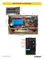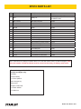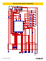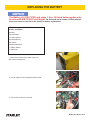
1
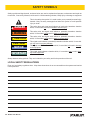
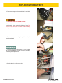
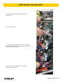
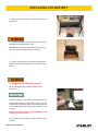
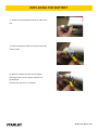
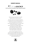
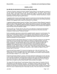
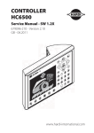
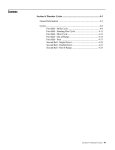
EPX10
PIN BRAZING UNIT
Safety, Operation and Maintenance
USER MANUAL
© 2013 Stanley Black & Decker, Inc.
New Britain, CT 06053
U.S.A.
73157 6-2015 Ver-7
DECLARATION OF CONFORMITY
DECLARATION OF CONFORMITY
ÜBEREINSTIMMUNGS-ERKLARUNG
DECLARATION DE CONFORMITE CEE
DECLARACION DE CONFORMIDAD
DICHIARAZIONE DI CONFORMITA
Hydraulic Tools
______________________________________________________________________
I, the undersigned:
Ich, der Unterzeichnende:
Je soussigné:
El abajo firmante:
lo sottoscritto:
Weisbeck, Andy
Surname and First names/Familiennname und Vornamen/Nom et prénom/Nombre y apellido/Cognome e nome
hereby declare that the equipment specified hereunder:
bestätige hiermit, daß erklaren Produkt genannten Werk oder Gerät:
déclare que l’équipement visé ci-dessous:
Por la presente declaro que el equipo se especifica a continuación:
Dichiaro che le apparecchiature specificate di seguito:
1.
Category:
Kategorie:
Catégorie:
Categoria:
Categoria:
Digital Pin Braze / ECONECT Unit (Product Group-Railroad)
2.
Make/Marke/Marque/Marca/Marca
Stanley Hydraulic Tools
3.
Type/Typ/Type/Tipo/Tipo:
EPX10 ECONECT (Digital Pin Braze unit)
4.
Serial number of equipment:
Seriennummer des Geräts:
Numéro de série de l’équipement:
Numero de serie del equipo:
Matricola dell´attrezzatura:
All
Has been manufactured in conformity with
Wurde hergestellt in Übereinstimmung mit
Est fabriqué conformément
Ha sido fabricado de acuerdo con
E’ stata costruita in conformitá con
Directive/Standards
Richtlinie/Standards
Directives/Normes
Directriz/Los Normas
Direttiva/Norme
IEC
EN
EMC : EN
EN
IEC
EN
Low Voltage Directive
EMC Directive
No.
Nr
Numéro
No
n.
950: 1991
60950: 1988, 60204-1
50082-2: 1995
55022: 1988 Class B/CISPR 22: 1985 class B
801-2: 1991
55101-2: 1990, 8kV CD, 15kVAD
73/23/EEC
89/336/EEC, 89/392/EEG, 91/368/EEG
Approved body
Prüfung durch
Organisme agréé
Aprobado
Collaudato
Safetrack Baavhammar AB
L. Mölleberga
245 93 Staffanstorp
Sweden
5.
Special Provisions:
None
Spezielle Bestimmungen:
Dispositions particulières:
Provisiones especiales:
Disposizioni speciali:
6.
Representative in the Union: Patrick Vervier, Stanley Dubuis 17-19, rue Jules Berthonneau-BP 3406 41034 Blois Cedex, France.
Vertreter in der Union/Représentant dans l’union/Representante en la Union/Rappresentante presso l’Unione
Done at/Ort/Fait à/Dado en/Fatto a Stanley Hydraulic Tools, Milwaukie, Oregon USA
Signature/Unterschrift/Signature/Firma/Firma
Position/Position/Fonction/Cargo/Posizione
2 ► EPX10 User Manual
Director of Product Development
Date/Datum/le/Fecha/Data
2-12-2013
TABLE OF CONTENTS
DECLARATION OF CONFORMITY...........................................................................................................................2
SAFETY SYMBOLS...................................................................................................................................................4
SAFETY PRECAUTIONS...........................................................................................................................................5
CHARGING THE BATTERY.......................................................................................................................................6
PREOPERATION.......................................................................................................................................................7
OPERATION...............................................................................................................................................................8
SPECIFICATIONS....................................................................................................................................................10
MAINTENANCE....................................................................................................................................................... 11
TROUBLESHOOTING.............................................................................................................................................15
ACCESSORIES.......................................................................................................................................................16
PARTS ILLUSTRATION...........................................................................................................................................20
PARTS LIST.............................................................................................................................................................21
ELECTRICAL DIAGRAM..........................................................................................................................................22
REPLACING THE BATTERY (applies only to units S/N 1215090 and below)......................................................... 23
IMPORTANT
To fill out a Product Warranty Validation form, and for information on your warranty,
visit Stanleyhydraulics.com and select the Company tab, Warranty.
(NOTE: The warranty Validation record must be submitted to validate the warranty).
SERVICING: This manual contains safety, operation, and routine maintenance instructions. Stanley Hydraulic Tools
recommends that servicing of the ECONECT unit, other than routine maintenance, must be performed by an authorized and certified dealer. Please read the following warning.
WARNING
SERIOUS INJURY OR DEATH COULD RESULT FROM THE IMPROPER REPAIR OR
SERVICE OF THIS TOOL.
REPAIRS AND / OR SERVICE TO THIS TOOL MUST ONLY BE DONE BY AN
AUTHORIZED AND CERTIFIED DEALER.
For the nearest authorized and certified dealer, call Stanley Hydraulic Tools at the number listed on the back of this
manual and ask for a Customer Service Representative.
EPX10 User Manual ◄ 3
SAFETY SYMBOLS
Safety symbols and signal words, as shown below, are used to emphasize all operator, maintenance and repair actions which, if not strictly followed, could result in a life-threatening situation, bodily injury or damage to equipment.
This is the safety alert symbol. It is used to alert you to potential personal injury
hazards. Obey all safety messages that follow this symbol to avoid possible
injury or death.
DANGER
This safety alert and signal word indicate an imminently hazardous situation
which, if not avoided, will result in death or serious injury.
WARNING
This safety alert and signal word indicate a potentially hazardous situation
which, if not avoided, could result in death or serious injury.
CAUTION
This safety alert and signal word indicate a potentially hazardous situation
which, if not avoided, could result in death or serious injury.
CAUTION
This signal word indicates a potentially hazardous situation which, if not avoided, may result in property damage.
NOTICE
This signal word indicates a situation which, if not avoided, will result in damage
to the equipment.
IMPORTANT
This signal word indicates a situation which, if not avoided, may result in damage to the equipment.
Always observe safety symbols. They are included for your safety and for the protection of the tool.
LOCAL SAFETY REGULATIONS
Enter any local safety regulations here. Keep these instructions in an area accessible to the operator and maintenance personnel.
4 ► EPX10 User Manual
SAFETY PRECAUTIONS
Tool operators and maintenance personnel must always
comply with the safety precautions given in this manual
and on the stickers and tags attached to the tool and
hose.
These safety precautions are given for your safety. Review them carefully before operating the tool and before
performing general maintenance or repairs.
Supervising personnel should develop additional precautions relating to the specific work area and local
safety regulations. If so, place the added precautions in
the space provided in this manual.
This tool will provide safe and dependable service if
operated in accordance with the instructions given in
this manual. Read and understand this manual and any
stickers and tags attached to the tool before operation.
Failure to do so could result in personal injury or equipment damage.
• Do not operate a damaged, improperly adjusted, or incompletely assembled tools.
• To avoid personal injury or equipment damage, all tool
repair, maintenance and service must only be performed
by authorized and properly trained personnel.
• Do not exceed the rated limits of the tool or use the tool
for applications beyond its design capacity.
• Always keep critical tool markings, such as labels and
warning stickers legible.
• Always replace parts with replacement parts recommended by Stanley Hydraulic Tools.
• Charging the battery can only be carried out between
0°C to +45°C (32°F to 113°F).
• Operator must start in a work area without bystanders.
The operator must be familiar with all prohibited work
areas such as excessive slopes, dangerous terrain conditions, and rail traffic.
• Establish a training program for all operators to ensure
safe operation.
• Do not operate the tool unless thoroughly trained or
under the supervision of an instructor.
• Always wear safety equipment such as goggles, ear,
head protection, and respiratory protection at all times
when operating the tool.
• Do not inspect or clean the tool while the battery power
source is connected. Accidental arcing can cause serious injury.
• Do not load brazing pins or ceramic rings while the battery power source is connected. Accidental arcing can
cause serious injury.
• Do not use the tool while it is connected to a battery
charger.
• Ensure battery charging is only done in a dry environment. Charging batteries in the rain or near standing
water presents an electrocution hazard. Read the safety and operation instructions provided with the battery
charger before using the battery charger.
EPX10 User Manual ◄ 5
CHARGING THE BATTERY
Connect the charger to the “grinder / charging” outlet on the unit then plug in the power cord.
The battery is fully charged after about 4 hours (if completely discharged).
NOTICE
CAUTION
CHARGING THE BATTERY CAN ONLY BE
CARRIED OUT BETWEEN 0°C to +45°C
If the batteries are left uncharged, they
may be damaged.
LED
Battery charging
The battery 95% charged.
The battery 100% charged
LED
The battery temperature below 0 or above 45C°.
Battery temperature OK.
6 ► EPX10 User Manual
PREOPERATION
GENERAL PROTECTION
Store the Electronic Pin Brazing Unit in a place where it is
protected from the elements, abrasive dust, and damage.
Use only recommended repair and replacement parts and
materials specified in this manual.
Use only recommended accessories also specified in the
this manual.
Do not use the Electronic Pin Brazer for applications it was
not designed for.
Use the carrying handle to transport the unit from location
to location.
CLEANING
Establish a routine to keep the unit as free from dirt as possible – daily, or at each shift change, for example.
Pin Brazers exposed to rain, sand, or grit-laden air should be
cleaned prior to each use.
Keep tool labels and stickers legible.
PREOPERATION PROCEDURES
Before putting a new ECONECT Pin Brazing unit into initial
service, or after an extended period of being unused, perform
a visual inspection for bent, broken, cracked, missing or worn
components.
INITIAL SETUP AND BATTERY CHARGING
WARNING
Failure to follow the instructions in the battery charger
operation manual can result in battery explosion and
serious bodily injury. To reduce the risk of battery explosion, read and understand the safety and operation
instructions in the battery charger operation manual,
the instructions published by the battery manufacturer,
and the instructions in this manual before attempting to
charge the batteries.
EPX10 User Manual ◄ 7
OPERATION
PREPARE THE RAIL SURFACE
Select the type and length of bonding cable to use for the
bond and use it as a guide to determine where brazing points
on the rail will be required.
Before brazing, the rail must be cleaned of rust, corrosion,
paint, pits, or other contamination at the points where the brazing is going to be done and on an area close to the brazing for
placement of the grounding cable. Cleaning is accomplished
with a grinder to ensure clean, bare metal.
b. The pin holder is threaded onto a threaded shaft in the gun
and locked in place with a nut. Place an open end wrench
over the nut and an open end wrench over the flats on the
pin holder. While holding the nut in place, unscrew the pin
holder counter clockwise.
Pin Holder
Ring Holder
Nut
CAUTION
Always use eye protection when grinding and brazing.
1. Grind the surface of the rail where brazing is going to be
done, until the surface shows shiny metal, free of rust, corrosion, pits, or other contamination. When grinding, use the
edge of the grinding wheel - not the face of the wheel.
2. Grind the surface of the rail where the grounding cable
will be placed to ensure a good ground. The grounding cable
should be placed in close proximity to the brazing area. If using a magnet ground try to attach the magnet within 0.5m/20
in. of brazing area. Ground should be on same work piece
where pin brazing is taking place.
PLACING THE GROUNDING CABLE
3. When finished grinding the rail for placement of the grounding cable, place the grounding cable on the cleaned surface
and then insert the other end into the twist lock receptacle in
the Econect unit marked "GROUND" and twist to lock.
SELECT PINS AND RINGS
Figure 3. Pin and Ring Holder
c. Install the correct pin holder and tighten it securely against
the nut.
IMPORTANT
Warning! Never rotate the shaft when mounting the pin
holder, it can damage the gun.
d. Install the correct ring holder by placing it over the pin holder
and into the circular groove in the gun, and finally, pushing
on it to seat it in place.
LOADING PIN AND RING
6. Insert the brazing pin into the pin holder. The rounded tip
should be facing away from the gun.
7. Insert the ceramic ring into the ring holder. The serrated
edge should be facing away from the gun. See figure 4.
Ceramic Ring
4. Select brazing pins and ceramic rings to match the specifications of the bonding cable you selected.
CHANGING PIN AND RING HOLDER
5. Check that the pin holder and ring holder on the gun are
the correct sizes for the brazing pins and ceramic rings you
selected. If the sizes are incorrect, the pin holder and ring
holder can be changed as follows:
a. The ring holder is a "push fit" to the gun. To remove it from
the gun, simply pull it away from the gun.
8 ► EPX10 User Manual
Brazing Pin
Figure 4. Loading pin and ring
OPERATION
• Connect the brazing gun, power and trigger cable to the unit.
• Connect the ground device to the unit, if not already connected.
• Press on/off button and select the right pin type by pressing the ”setting” button.
The unit will remember what setting was used last.
• Load the gun with brazing pin and ferrule, if not already loaded.
Selected setting
Error Indication
ON / OFF
Battery Indicator
Pin setting
Gun power
Gun control
Fuse for electronics
Fuse for grinding
/ charge
Grinding / charging
Ground
Make sure to braze in the top of the hole when
brazing to a vertical surface.
PIN BRAZE
• Hold the gun firmly with both hands against the work
piece and pull the trigger just once.
• The electronic unit will by itself finish the brazing process.
• Hold the gun in place for 3-4 seconds after the brazing is complete to allow for cooling.
• Remove the gun straight backwards without pulling
the trigger!
• Knock off the shank of the brazing pin with a hammer.
• The brazing is completed.
NOTE:
If the brazing is aborted to early “ERROR” will turn on.
The brazing should be redone for a good result.
The error lamp will turn off after 8 seconds
Use a new ceramic ring for each new pin braze.
NOTICE
The battery indicator “LOW BATT” flashes when
the batteries are almost discharged,
when the “LOW BATT” is constantly lit the batteries are discharged and you can’t do
any more pin brazing. Charge the battery.
EPX10 User Manual ◄ 9
SPECIFICATIONS
SPECIFICATIONS
Voltage............................................................................................................................................................................... 36 V DC
Number of Brazes (Per Charge)................................................................................................................................................... 50
Weight (incl. Battery)................................................................................................................................................ 9.8 kg / 21.6 lb
Width................................................................................................................................................................... 5.9 inch / 150 mm
Height.................................................................................................................................................................11.0 inch / 280 mm
Length............................................................................................................................................................... 12.5 inch / 320 mm
Temperature Range.........................................................................................................................-4° F - 130° F / -20° C - 55° C
EPX10 Econect Battery Kit (For Units S/N 1215091 and Up) ..........................................................................................73077
EPX10 Econect Battery Kit (For Units S/N 1215090 and Below) ......................................................................................73720
MAINTENANCE
EQUIPMENT
- Always make sure the batteries are fully charged.
- Check the cables from time to time for damage.
- Check the contact surface on the ground magnet from time to time to ensure a good connection.
- Make sure that the brazing pin with the ferule passes easily in the gun, centered.
BRAZING PINS AND FERRULES
-Keep them dry.
RAILBONDS AND CABLE LUGS
-Keep them free from oxidation.
-Keep them free from contamination like: Grease, oil.
-Make sure they are not damaged.
SETTING RIGHT LIFT HEIGHT
The S15 brazing gun self adjust to the same lift height every time.
See separate instructions in the maintenance section if adjustment for the gun is necessary.
PIN HOLDERS
Squeeze the fingers on the pin holder together each time you feel that the brazing pin goes in too easy when
mounting them into the pin holder. This is important since all the current goes thru the pin holder to the
brazing pin. If the fingers are too loose the pin holder will be damaged and must be replaced.
10 ► EPX10 User Manual
MAINTENANCE
Replace the fuses:
Push and unscrew counter-clockwise to remove fuse holder.
Replace fuse and re-install the fuse holder.
NOTE!
Control: 5A fuse.
Grinder: 15A fuse.
Special functions:
1. BATTERY INDICATOR:
Press and hold the “SETTING” button, while you push the “ON / OFF” button.
“LOW BATTERY” LED will light. Release the buttons.
The LEDs on the front panel show the charge status of battery.
2. LIFTING HEIGHT CONTROL:
First follow step 1 above.
Press “Settings” and the lights start flashing, at this point, you can check the
lifting height of the gun.
3. Pressing “Settings” one more time and you go back to battery indicator.
EPX10 User Manual ◄ 11
MAINTENANCE
Periodic maintenance of S15 automatic gun
1. Check that all cables and lugs are not damaged and properly tighten in gun and unit.
2. Check that the right pinholder is installed in the gun.
See selection of pinholders in the
accessories section of this manual.
Make sure the pinholder is tight on the gun, otherwise a spark can destroy the axle.
Use a wrench to hold the nut from turning and tighten the pinholder as shown in the
picture. Do not allow the main shaft to turn, only turn the pinholder to tighten. Use one
8mm and one 10mm wrench for 8-9,5 mm and M8 pinholders.
Two 10mm wrenches for M10 and M12 pinholders.
Make sure, never twist the main shaft when mounting the pinholder!
When loading the brazing pin, it should not go in loose into the pinholder, if it does
push the pinholder together with your fingers to gain a tighter fit. Otherwise you can
have a contact fault or a spark can arise if their is not a tight contact.
3. Check that the ringholder is the right type. You can remove it by hand and its ease
of removing can be adjusted with the small screw on the side of the gun (see photo).
Ringholder Adjustment
Screw
4. Load the gun with the appropriate pin & ferrule. Check that the axle moves easily
with the pin and ferrule installed by pushing back and forward on the pin with your
finger (see photo).
If the pin does not move easily, change either pinholder or ringholder.
If it still does not move easily the axle is damaged and must be sent for repair.
12 ► EPX10 User Manual
MAINTENANCE
Lift level tool
P/N-62394
IMPORTANT! The normal liftheight is 2mm / 0.078 in.
This is very important for the arc and energy amount.
Too high liftheight increase the risk of a “coldbrazing”,
too low liftheight reduce the time and increase misfires.
1. Insert this end in to the gun.
2. Press and hold “SETTING” and press =”ON/OFF”.
When “LOW BATTERY” is lit, release buttons.
Press “SETTING” and the leds will start to blink.
In this mode the unit is able to check the lift height.
Important! Press the tool completely against the gun then pull the trigger.
Otherwise the gun may be damaged!
Important! Hold the gun so the tool is horizontal.
3. The lift level is calibrated when the inner rod, made of brass, on the tool is in same level as the outer plastic
sleeve. Tolerance ±0,2 mm / 0.007 in. If the gun is not calibrated see seperate instruction for adjusting of the gun.
EPX10 User Manual ◄ 13
MAINTENANCE
Remove plastic plug with
a pin or sharp object.
Advanced maintenance work
Adjusting the liftlevel.
1. Resetting correct liftheight of a S15 gun.
Only reset a maladjusted gun.
Install the lift level tool (shown below) onto the gun.
2. Connect the cables to the pinbrazing unit and
switch on the power.
3. Take off the plastic plug with a pin in the upper
small hole in the front of the gun (see photo).
IMPORTANT, never adjust in the hole where the
big plug is!
4. When liftheight is too low. Use the 3mm hexagon
allen wrench and adjust the screw in the small hole
counter-clockwise about 1/4 of a turn then check with
the lift level tool.
5. When liftheight is too high. Use the 3mm hexagon
allen wrench and adjust the screw in the small hole
clockwise about 1/4 of a turn then check with the
lift level tool.
If height is ok, replace the plug in the hole.
If height is not ok, send for repair.
P/N-62394
Lift Level Tool
14 ► EPX10 User Manual
TROUBLESHOOTING
Error indications on the unit:
“ERROR” led is lit.
- The temperature of the battery is over +55 °C/131°F
Action: Wait until the light goes out, when the temperature drops you will be able to braze again.
“ERROR” led flashes.
- The temperature of the battery is below +10 °C/50°F
Action: Leave the unit on, the built-in heating element will heat up the battery. Wait until light goes out
and the temperature has risen, and you will be able to
braze again.
“ERROR” and ”LOW BATTERY” led flashes.
- The temperature of the battery is below +10 °C/50°F
and the battery is almost discharged.
Action: Charge the batteries.
“ERROR” Led is lit after a braze.
- The pin brazing was not complete.
Action: The braze should be remade to achieve good
results. The Led turns off after 8 seconds.
“ERROR” Led glows.
- Failure of a sensor in the unit.
Action: The unit should be sent for repair.
”LOW BATTERY” Led flashes.
- Battery is almost discharged
”LOW BATTERY” led is lit.
- Battery is discharged. Charge the batteries.
“NOTHING HAPPENS WHEN YOU PRESS THE
BUTTONS”
- The electronics may have gotten stuck.
Action: Remove control 5A fuse for a short time, put
it back again.
“THE BRAZING NEVER STOPS”
- The electronics may have gotten stuck.
Action: Remove the gun and the ground magnet from
the rails and disconnect them from the unit as soon as
possible. Remove the control 5A fuse, check that nothing has been damaged before the fuse is put back.
EPX10 User Manual ◄ 15
ACCESSORIES
BRAZING PINS & CERAMIC RINGS
STANDARD BRAZING PINS
Part No.
35835
35836
35837
35840
35841
35839
Description
8 mm
8 mm w/ extra silver
9.5 mm
M8/12 Threaded
M10 Threaded
M12 Threaded
Ceramic Ring Reqd
Brazing Pins are for
use on Rail Only
35832
35832
35833
35834
35834
35834
CERAMIC RINGS
Part No.
Description
35832
35833
35834
8 mm
9.5 mm
12 mm
PIN & RING HOLDERS
Part No.
Description
35826 35827 35828 35829 Pin Holder for Pinbrazing, 8-9,5 mm brazing pins.
Pin Holder for Pinbrazing, M8 Threaded pins.
Pin Holder for Pinbrazing, M10 Threaded pins.
Pin Holder for Pinbrazing, M12 Threaded pins.
35825 Extended pin and ring holder set for 8-9,5 mm brazing pins.
37945 35830 35831 Ring Holder, 8 mm pin & ringholder Set
Ring Holder, 8-9,5 mm ceramic rings.
Ring Holder, 12 mm ceramic rings.
35827 Pictured
35831 Pictured
CABLE LUGS (for Pin Brazing to rail)
Part No.
Description
Brazing Pin Reqd
47523 47524 47525 Braze Lug for 25 mm Cable 35836
Braze Lug for 35 mm Cable 35836
47523 Pictured
Braze Lug for 50 mm Cable 35836
39241 Pictured
39241 Cable Shoe #6 2 x 35836
35847 Cable Shoe 10 mm 35835
35855 Cable Shoe D=8 mm 35836
47526 47527 47528 47529 47522 Cable Lug for 16 mm Cable 47527 Pictured
Cable Lug for 25 mm Cable Cable Lug for 35 mm Cable Cable Lug for 50 mm Cable Cable Lug 5/8" ground rod to #2 cable 47521 Pictured
35835
35836
35836
35836
2 x 35836
47521 Braze Sleeve #6 to #6 41625 Pictured
Multi-Wire Track Connection 35836
41625 2 x 35836
35865 Clip for 18x5mm 35835
67122 Brazing Clip 35835
67122 Pictured
(Secures Wire to Rail)
16 ► EPX10 User Manual
ACCESSORIES
BONDING CABLE WITH LUGS (for Pin Brazing)
Part No.
35845
35844
39243
39244
37944
39705
39706
39707
Description
Brazing Pin Reqd
1 AWG / 50 mm², 185 mm long, copper
4 AWG / 25 mm², 145 mm long, copper
3/16 Bond, 300 mm long
25 mm², 200 mm long
50 mm², 185 mm long
Bond Wire 16" OAL x 25 mm
Bond Wire 24" OAL x 25 mm
Bond Wire 36" OAL x 25 mm
35837
35835
35835
35835
35836
35844 Pictured
35835
35835
35835
39242 Pictured
39242
3/16 Bond Crimpable Sleev
35835
40366
40091
40090
Signal Extension Bond 3/16" (170 mm)
Signal Extension Bond 150 mm L=430
Signal Extension Bond 2 x 35 mm - 2 x L=170
41635
58563
41815
43686
43519
41225
41226
66579
66580
66269
67634
73016
3/16 Signal Bond Wire W/Eye & Crimpable sleeve
35835
24 inch long
41635 Pictured
3/16 x 7”/180 mm Long with Electrode & Ferrule
3/16 Bond 12’ Long Eyelet one end, AL block for 35835
Tig Weld Other End
Extension Bond CU, 25 mm², x 330 mm Long
35835
3/16 Extension Bond 12"
35835
Bond Wire 34" Long C/L-C/L W/9 mm eyelets on
35835
both ends
Bond Wire 46" Long C/L-C/L W/9 mm eyelets on
35835
both ends.
25mm2 x 500mm Extension Bond 35835 25mm2 x 900mm Extension Bond
35835
Signal Bond 3/16" x 6' Braze Lug Both Ends
35835
67634 Pictured
Railbond 300 mcm L=330 mm Uninsulated
35837
(4) 9.5 Pins Required
Railbond 300 MCM
72988
72989
73016
67635
Railbond 3/16, 4 in. Reversed (50 pack)
Railbond 3/16, 6 in. Reversed (50 pack)
300MCM Rail Bond
Extension Bond 300 mcm x 200 mm crimp sleeve
(2) 9.5 Pins Required
47530
Bungalow Grounding Bond 3/16"
35835
35837
35836
40366 Pictured
35837
67635 Pictured
35836
"T" CONNECTORS
(for Pin Brazing)
TYPE C
Part No.
35857
Description
Brazing Pin Reqd
Copper Plate with M8 x 18 Brass Threaded Stud
35835 x 2
TYPE D
Part No.
35860
35861
35857 Pictured
Description Brazing Pin Reqd
Copper Plate with M16 x 26 Staniless Steel Threaded Stud 35837 x 4
Copper Plate with M16 x 32 Stainless Steel Threaded Stud 35837 x 4
35860 Pictured
EPX10 User Manual ◄ 17
ACCESSORIES
Grinder Abrasives
Part No.
Description
73052
Bull Nose Stone 2 in. Dia, (1/4 in. Shank)
66976
Bull Nose Stone BNSF 2 in. Dia, (1/4 in. Shank)
73358
Carbide Burr SF 5 (1/4 in. Shank)
GRINDER
Part No.
Qty
Description
HGE12141
Cordless Grinder - Includes: (Grinder Only) NO Battery or Charger
HGE12151
Cordless Grinder Kit (Includes: Grinder, Battery and Charger)
HGE12161
Cordless Grinder Kit (Includes: Grinder, Battery, Charger and
Bull Nose Stone)
HGE12161B
Cordless Grinder Kit (Includes: Grinder, Battery, Charger, Bull Nose
Stone and BNSF Stone)
73399
Battery 18V and Charger 120V
73400
Battery 18V
Fuses, Chargers, & Batteries
Part No.
Description
Control Fuse, 5A
Grinder Fuse, 15A
72972
Charger 36 V / 110 V ECONECT
73077
Econect Battery Kit
18 ► EPX10 User Manual
ACCESSORIES
CABLES
Part No.
Description
72999
ECONECT Ground Magnet______________________________
72973
Carrying Strap__________________________________
66266
Ground Clamp Assembly (Vise Grip Style)_______________
72974
Carrying Case___________________________________
72970
Econect Unit______________________________________
EPX10340
SafeBond Kit Econect (Includes: BG20600 Brazing Gun Econect Safebond,
72970 Econect Unit, HGE12151 Grinder Elec Cordless Kit, 72972
Charger 36V/110V Econect, 72973 Carrying Strap, and 72974 Carrying Case, 73358 Carbide Burr).
72975
Econect Kit - (Includes: 72971 S-15 Automatic Brazing Gun,
72970 Econect Unit, HGE12151 Grinder Elec Cordless Kit, 72972
Charger 36V/110V Econect, 72973 Carrying Strap, and 72974 Carrying Case, 73358 Carbide Burr)
GUNS
Part No.
Description
72971
S-15 Automatic Brazing Gun_____________________________
73078
Econect S-15 Gun Cable________________________________
BG20600
Brazing Gun Econect Safebond___________________________
EPX10 User Manual ◄ 19
EPX10 PARTS ILLUSTRATION
ECONECT – Part Sheet
Q1-6
D1-6
R5
K1
M1
C1,C2
F1
L1
BT1 AND R4+F4+R3
FRONT PANEL
S1,S2
J4
J5
F3
F2
20 ► EPX10 User Manual
J3
J2
EPX10 PARTS LIST
Qty
References
Description
Part number
1
K1
Econect circuit board
74590
1
BT1
Battery Kit
73720 FOR UNITS SERIAL # 1215091
& HIGHER ONLY
1
R4+ F4+R3
Heat pad complete.
74592
1
R5
Shunt 150A
74593
6
Q1-Q6
Mosfet
74594
6
D1-D6
Diode
74595
1
L1
Triode
74596
2
C1,C2
Capacitor
74597
1
M1
Fan
74598
Front panel
74599
1
1
J3
Wall socket 4-pin
74611
1
J4
Wall socket 5-pin
74612
1
J2
Wall socket for ground, female
74613
1
J1
Wall socket for gun, male
74614
2
S1,S2
Pushbutton
74640
1
F1
Fuse 300A 58V
74641
1
F2
Fuse 15AF 5x20mm
74642
1
F3
Fuse 5AT 5x20mm
74643
2
F2-F3
Fuse holder for 5x20 fuses
74644
NOTE: Reference BT1 Battery Kit shown above is for units with serial number 1215091 and higher, Units
with serial number 1215090 and below must be returned to the factory for battery replacement.
Econect battery kit P/N-73720 for serial number
1215091 and Higher only.
Including:
Econect battery.
2 x 13mm spanner.
3mm hexagon key.
Side cutters.
Resistor 22Ohm/4W.
2 x Plastic washer.
3 x Cable ties.
EPX10 User Manual ◄ 21
R4
1
F1
BT1
R2
R1
BATTERY
F4
R3
BATTERY BOX
C2
C1
2
Q3
D3
3
Q4
D4
Q5
D6
Gate 6
S
Q6
D5
GUN
GND
K1
Econect styrkort
Löd volt IN
Q2
D2
Gate 3
SHUNT +
HEAT
FAN
Gate 1
SHUNT -
Gate 5
Q1
D1
M1
FAN 24V
R5
Gate 2
A
B
D
E
F
G
H
4
ON/OFF
SETTING
TEMP 1
TEMP 2
TEMP 3
FrontLED
L1
5
Creation Date
2009-10-29
6
ECONECT_shema.sch
File name
Safetrack AB
Modif. Date
2014-01-09
FRONTPANEL
Safetrack AB
D7
D8
D9
D10
D11
D12
L. Mölleberga
245 93 Staffanstorp
Sweden
Tel. +46(0)40445551
7
+1
-1
+2
-2
1
2
3
4
5
J2
F2
F3
J1
J3
J4
GUN
FUSE 15AF
FUSE 5AT
GRINDER 15A
CONTROL 5A
GRINDER CHARGING
GUN
S1
ON/OFF
S2
SETTING
8
22 ► EPX10 User Manual
C
EPX10 ELECTRICAL DIAGRAM
Gate 4
TRIG
VCC
REPLACING THE BATTERY
The Battery kit (P/N-73720) and steps 1 thru 19 listed below applies only
to units with S/N 1215091 and Higher. For Units with serial number 1215090 & below,
these units must be returned to the factory for battery replacement.
Econect battery kit P/N-73720 for serial number
1215091 and Higher.
Including:
Econect battery.
2 x 13mm spanner.
3mm hexagon key.
Side cutters.
Resistor 22Ohm/4W.
2 x Plastic washer.
3 x Cable ties.
1. Remove all screws on the sides of the unit
with a 3mm hexagon key.
2. Cut the cable ties for the positive and fan cable.
3. Pull out the connector for the fan.
EPX10 User Manual ◄ 23
REPLACING THE BATTERY
4. Remove all screws on the backside of the unit with
a 3mm hexagon key and remove the back.
5. WARNING: RISK FOR SHORT CIRCUIT.
With two 13mm spanners remove the batteries
positive cable, also remove the bolt and fuse. Be
careful so the cables don’t come in contact with any
other parts in the unit.
6. Directly after disconnecting the positive cable, it
must be insulated.
7. Hold the cable for the electronics on to the copper
rail and press ON and hold it for at least 30 seconds,
to discharged the capacitors.
8. Cut the cable tie, pull out the cable.
24 ► EPX10 User Manual
REPLACING THE BATTERY
9. Remove the batteries negative cable from the
current shunt.
10. Pull out the cable.
11. Pull out the black cables connector form the top
socket (TEMP1) and the blue cables connector form
the bottom socket (TEMP3).
12. Remove the two connecters on the charger
outlet, that aren’t soldered.
EPX10 User Manual ◄ 25
REPLACING THE BATTERY
13. Make sure that all cables are free then pull out the
battery box.
14. Replace the battery, make sure that the battery is
placed in the same way as the old.
WARNING: Connecting the battery in the wrong
way will cause damage to the electronics.
15. Slide in the new battery and start connecting the
cables in the reversed order, start from step 12 up to
step 8.
16. WARNING: RISK FOR SHORT CIRCUIT.
Mount the M8 bolt with a plastic washer on the
copper rail.
Before the battery is connected, the capacitors must
be charged. Hold the resistors that came in the kit in
contact with the positive lead of the battery and connect the other lead to the copper rail, hold for 15 to 20
seconds.
Continue with the next step immediately, if not
charging must be redone.
After charging set the resistor aside for future use if
needed.
26 ► EPX10 User Manual
REPLACING THE BATTERY
17. Mount the fuse and batteries positive cable on the
bolt.
18. Mount the positive cable for the electronics and a
plastic washer.
19. Mount the washer and lock nut and tighten.
Don’t tighten too hard, the plastic washers may
get damaged.
Continue with step 4 to1, to complete.
EPX10 User Manual ◄ 27
Stanley Hydraulic Tools
3810 SE Naef Road
Milwaukie, Oregon 97267-5698 USA
(503) 659-5660 / Fax (503) 652-1780
www.stanleyhydraulics.com