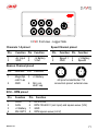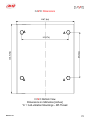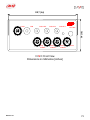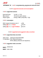
1
Standalone version
Release 1.01
1
USER Manual for
DAVID
This User Manual was written using the following parameters:
Software version Race Studio 2:
2.20.14
Firmware version DAVID:
17.06
Firmware version MyChron 3 Dash:
15.04
Firmware version MyChron Light TG Dash:
21.01
Manual Version:
1.01
Date of publication:
August 30th 2005
Please note:
This user manually is copyright of Aim s.r.l.; all procedures You find here
explained can change also substantially so, please refer to our website
www.aim-sportline.com to know which are the newest procedure.
Aim reserves the right to update and re-issue documentation from time to
time without obligation to notify any person of such changes.
Release 1.01
2
DEAR DAVID OWNER
DAVID is the new AIM system that allows you to enter in the race
movie world because with DAVID you are the director!
DAVID merges the signals of two video cameras with your dash
display and you will be able to see your race together with the most
important information right in front of you.
Moreover, with ECT (Easy Connection Technology), DAVID
connects to the most popular ECU through a single CAN or RS232
connection and you can select your own one from a custom
database.
As all AIM products, DAVID let you choose your preferred
configuration through the powerful RACE STUDIO 2 Software, that
supplies you an easy data analysis instrument too. DAVID, in fact,
has also an integrated data logger with 8Mb of non volatile internal
memory and all data there stored can be downloaded to your Pc
through a fast USB cable.
Thank you for your purchase of DAVID and… enjoy yourself!
Release 1.01
3
TABLE OF CONTENTS
TABLE OF CONTENTS ......................................................................................... 4
1 – DAVID IS FOR.................................................................................................. 6
2 – DAVID Standalone architecture..................................................................... 7
3 – DAVID Standalone standard kit and accessories........................................ 8
3.1 – DAVID installation and power
9
3.2 – DAVID LanC connection
11
3.3 – DAVID maintenance
12
4 – DAVID Dash (optional).................................................................................. 13
4.1 – MyChron 3 Dash
13
4.2 – MyChron Light TG Dash
16
5 – Race Studio 2 Software ................................................................................ 17
Note 1: “Race Studio 2” Visualization problems
19
6 – DAVID Configuration .................................................................................... 23
6.1 – How to set and select a Configuration
24
6.2 – How to set DAVID Channels
26
6.3 – How to set and use DAVID Displays
30
6.3.1 – How to configure MyChron 3 Dash
6.3.2 – Other keyboard functions of MyChron 3 Dash
(data recall, total running, odometer, firmware, serial nr.)
6.3.3 – How to configure MyChron Light TG Dash
6.3.4 – Other keyboard functions of MyChron Light TG Dash
(data recall, data clear, obscuring time, track options, firmware, serial nr.)
6.4 – How to configure DAVID Video
Note 1: “Graphic object visualization”.
Note 2: “Sampling Frequency”
Note 3: “Video objects limits”
31
32
32
33
37
37
40
48
49
50
7 – Sensors management................................................................................... 52
7.1 – How to configure a custom sensor (expert users only)
52
7.2 – How to calibrate a sensor
55
8 – How to download a test................................................................................ 57
Release 1.01
4
8.1 – Downloading a test
58
8.2 – Inserting the test in a database
61
9 – How to use Race Studio Analysis ............................................................... 63
9.1 – How to load a test
65
9.2 – How to plot a channel
67
APPENDIX “A” - DAVID technical notes........................................................... 70
DAVID Pinout
70
DAVID Dimensions
72
APPENDIX “B” - DAVID complementary equipments technical notes ......... 74
DAVID supported cameras and consumption
74
DAVID supported and suggested video-recorders
74
ADRESSES .......................................................................................................... 75
Release 1.01
5
1 – DAVID IS FOR
DAVID, the new AIM Data Video recording system, merges in one only
image the signals coming from up to two cameras with your dash display.
This means you can see, together with the images of your race, all
needed information like RPM, lap and split times, best lap time,
temperature and pressure values and so on, all depending only on you.
No matter what you are: a serious racer, an amateur, a race driving
teacher, a consultant, a marketing manager or something else, DAVID is
the tool that will make the difference between you and the others. Through
this new powerful system, in fact, you can create different products you
can use in different ways.
Through DAVID you can create video for sponsorship packages or for
educational use. Moreover you can customize the video layout setting
gauges style colours and inserting your logo.
DAVID is a very powerful communicational weapon and, further more,
enjoying too.
Release 1.01
6
2 – DAVID Standalone architecture
Figure 1: DAVID standalone architecture
Release 1.01
7
3 – DAVID Standalone standard kit and accessories
DAVID standalone version standard kit is made of:
•
DAVID video system core
•
System harnesses
•
Race Studio 2 software and USB data download cable
•
Infrared receiver and transmitter for lap / split time
•
Wheel speed sensor
•
Wiring for ECU interface (via CAN or RS232)
•
RPM sensor
•
Lateral and longitudinal G-sensor
DAVID standalone optionals are:
•
Standard NTSC or PAL cameras
•
Standard NTSC or PAL video recorder
•
MyChron 3 Dash or MyChron Light TG Dash
•
Oil and water temperature sensors
•
Oil and fuel pressure sensors
•
Brake / Throttle / Steering wheel potentiometers
Release 1.01
8
3.1 – DAVID installation and power
Please install DAVID in an aerated place like in place of the passenger
seat or of the rear seat. Please do not install DAVID under any seat. It
should not be in contact with oil or fuel nor too close to heat sources. We
strongly recommend to protect it from vibrations using the anti vibration
mountings / silent blocks you find in the kit.
Warning: DAVID system warms up while working, so do not to touch it
with your hands after it has been working for a while.
Please remember that your DAVID is not equipped with internal batteries
so it need to be powered by an external 9-15 VDC power source.
This can be done in two ways:
•
connecting it to the master switch of your vehicle (we
recommend you to do so)
•
connecting it directly to the battery of your vehicle.
Depending on how you decide to power it, DAVID works in different ways.
• if you connect DAVID to the master switch of your vehicle it switches
on/off when you switch on/off your vehicle. As you can see in
Figure 2, on the right part of DAVID is an ON/OFF button you can
use to manually switch ON/OFF the system. To manually switch
OFF DAVID, please press for 3-4 seconds ON/OFF button. To
switch the system on again you can both switch off your vehicle and
then re-switch it on or push again ON/OFF button.
Release 1.01
9
• if you connect DAVID directly to the battery of your vehicle it is
always switched on. This means that to switch it OFF you need to
press for 3-4 seconds ON/OFF button. Of course if you switched
manually OFF DAVID you need to re-switch it ON manually.
Figure 2: DAVID front panel - video side
Please note: no matter how you decide to power your DAVID (if
connecting it to the master switch of your vehicle or directly to your vehicle
battery), the only power input to be used is the one labelled as “Power” on
the front panel, video side, of DAVID (red circled in Figure 2).
Moreover if you have cameras equipped with audio channels or if you add
audio channels to your system, they have to be connected to your videorecorder / video-camera and not to DAVID.
Release 1.01
10
3.2 – DAVID LanC connection
LanC is a serial connection to a camcorder or VCR (Video Cassette
Recorder) that allows a wired remote control of camera and VCR functions
such as: Play, Record, Stop, Pause, Fast Rewind, Fast Forward, Search
Rewind, Search Forward, Step +/-.
Our DAVID system uses LanC communication to start and stop recording
on the connected camcorder or VCR. The trigger is the same used for
data logging: RPM signal greater than 500 or wheel speed over 10km/h
(6 MPH).
This is to say that with the camera powered on and connected to DAVID,
the system controls the camera recording without any user intervention.
When DAVID starts recording a signal is sent to the camera to start
recording video; in the same way when the vehicle is stopped and the
engine is off DAVID stops recording data and sends a "Stop" signal to the
camcorder or VCR. Included with each DAVID systems is a LanC cable.
If you want to manually manage VCR or camcorder Start/Stop functions
you only need to unplug the LanC cable form the device and you can
manually manage these functions.
LanC output is blue circled in Figure 2.
Release 1.01
11
3.3 – DAVID maintenance
DAVID does not need any special maintenance. Provided that you take
adequate care of all components, the only required maintenance is
periodical software and/or firmware upgrading. To upgrade the software /
firmware, please connect to our website www.aim-sportline.com and
check in software download page if any software / firmware release has
been issued. If so, please follow this procedure:
•
download the software / firmware from our website and run it;
•
follow the instruction prompted on your Pc monitor.
The present user manual has been written using the following parameters:
•
Software: Race Studio 2 – Version 2.20.12
•
Firmware:
DAVID – Version 15.03
MyChron 3 Dash – Version 15.04
MyChron Light TG Dash – Version 21.01
Release 1.01
12
4 – DAVID Dash (optional)
Your DAVID system can also be equipped with an optional external dash.
Dashes at present available for DAVID are MyChron 3 Dash and
MyChron Light TG Dash.
4.1 – MyChron 3 Dash
MyChron 3 Dash is a complete and robust dashboard that displays lap
time, lap number, RPM, speed and up to 4 analog inputs (temperatures or
pressures). Moreover MyChron 3 Dash has a low battery warning feature
and displays battery voltage.
MyChron 3 Dash has 10 configurable sequential shift lights, 4 alarm led
for High/Low temperature/pressure alarms and a small integrated gear
display.
MyChron 3 Dash can show the engaged gear number either sampled
from an “on-board” gear sensor or calculated from RPM vs. Speed ratio.
Please refer to Figure 3 to know which information are displayed and
where.
Release 1.01
13
Engaged gear number
RPM graphical bar
Configurable RPM scaling
10 fully configurable shift lights
Speed
Unit of
Measure
3
2nd Displayed
Channel
Low battery warning
Night Vision
\
Temp.
Unit of
Measure
Alarm Led
Displayed
Channels
RPM Digital Value
Speed
Best Lap Time
Battery voltage
USB Port
For firmware
upgrade
1st Displayed
Channel
Switches between
Pages 1 and 2 of the
display
Lap / Split Times
Figure 3: MyChron 3 Dash Display
Release 1.01
14
To install MyChron 3 Dash, we recommend you to choose a place where
the logger will not be in contact with oil or fuel. Please ensure that the
logger is not installed too close to heat sources and protect it from
vibrations (if possible use anti vibration mountings / silent blocks).
Please remember that your MyChron 3 Dash is not equipped with internal
batteries and is powered by your DAVID system so, please remember to
connect DAVID system to an external 9-15 VDC Power source to switch
the dash on.
MyChron 3 Dash does not need any special maintenance, provided that
adequate care is taken of display unit and components.
For more information about MyChron 3 Dash, please refer to “How to set
and use DAVID displays” chapter – “MyChron 3 Dash Paragraph”.
Release 1.01
15
4.2 – MyChron Light TG Dash
MyChron Light TG Dash is a “pocket” dash mainly useful if you do not
have a lot of space and want to immediately see some important value. It
can show you lap times, split times or variation times depending on how
you set it. Its display is constituted of two main lines you can configure so
to show: lap time, split time and variation split and lap times.
MyChron Light TG Dash is settable via keyboard and you need to use
Race Studio 2 only to set the Displayed speed among these available.
For further information about MyChron Light TG Dash please refer to
“How to set and use DAVID displays” chapter - MyChron Light TG Dash”
paragraph.
Release 1.01
16
5 – Race Studio 2 Software
Once DAVID installed and the sensors plugged in it, to acquire correct
information you need to configure it using Race Studio 2, the Software
developed by AIM to configure its instruments and analyze stored data.
In DAVID package you find also a CD Rom containing the software.
Please insert it in the CD Rom drive and, if auto-play option is enabled,
the installation starts automatically, otherwise browse the CD and click
twice on setup icon. Please follow the instruction that are prompted on
your Pc monitor. For any doubt about Software and USB drivers
installation, please refer to download page of our site: www.aimsportline.com, where is a file called “Installation_xxx.pdf”.
Once the software installed, please run it. This window appears1:
Figure 4: Race Studio 2 First window
1
If you notice a wrong visualization (like displaced or overlapped buttons), please
see Note 1 “Race Studio 2 visualization problems” at the end of this chapter.
Release 1.01
17
Please click on DAVID Button on the left toolbar : this window appears
Figure 5: Race Studio 2 – New Configuration window
Please fill in all the fields of this window and click on “OK” button. System
Manager window appears
Figure 6: Race Studio 2 – System Manager window
Release 1.01
18
Note 1: “Race Studio 2” Visualization problems
If when you run Race studio 2 you monitor shows you a distorted image,
like the one here below reported, you need to change your screen
settings. In the example below we pressed “MXL” button.
First of all, please close all applications you are running, Race Studio 2
included because after this operation you need to re-start your Pc.
Release 1.01
19
To change your screen settings:
< Click on “Start/Settings/Control Panel/Display
< Display Properties windows appears
< enable Settings layer
< Press Advanced button
< Set DPI setting on “Normal Size (96 DPI)”
Release 1.01
20
< Click on “OK” button
< Click on “Apply” button
< If this message appears, please click on “Yes” button
Release 1.01
21
< Click on “Close” button
< Click on “Yes” button and re-start your computer.
< After re-start run “Race Studio 2” and all works properly.
Release 1.01
22
6 – DAVID Configuration
Through Race Studio 2 you can configure your DAVID system and its
displays (if you bought one). This is possible through “System Manager”
window (Figure 6) and its four layers.
On top of “System Manager” window are two pushbuttons
To transmit the configuration to the logger
To read the configuration from an unknown
logger and store it in your configuration
database
Under them is a row called “Current Configuration” (highlighted with an
arrow in Figure 6) that is always on top to inform you which configuration
you are working on.
To fully configure your DAVID system you need to activate, one by one, all
the layers “System Manager” window is composed of, to say:
• Select Configuration
• Channels
• Display
• Video Configuration
Release 1.01
23
6.1 – How to set and select a Configuration
< activate “Select Configuration” layer (Figure 7):
Figure 7: Race Studio 2 System Manager window – Select layer
< press “New” button to create a new configuration
< press “Delete” button to delete an existing configuration
< press “Clone” button to Clone an existing configuration
< press “Import” button to import a configuration in your database
< press “Export” button to export a configuration from this database and
be thereby able to import it elsewhere
< fill in “Lap” and “Unit of measure” boxes (see below);
< Select a configuration to set it (in Figure 7 the selected configuration is
the first, highlighted in yellow)
Release 1.01
24
Lap Box:
Obscuring time is a period during which the receiver is blind and cannot
detect lap signals (accepted values from 3 to 100 seconds); use it if you
are on a track where more than one transmitter is installed and you do not
want to record split times: set it to a value lower than your best lap time and
greater than the time elapsed between last split and start/Finish line
Lap segment is the number of split your track is divided in (accepted
values are from 1 to 6).
Measure Units box:
Choose your Speed Measure Unit (km/h or mph) and your Temperature
Measure Unit (°C or °F)
Release 1.01
25
6.2 – How to set DAVID Channels
< activate “Channels” layer (Figure 8) and:
Figure 8: Race Studio 2 System Manager window – Channels layer
< fill in RPM box
< fill in Speed boxes or disable them
< set Gear sensor box and reference speed2
< set channels table
2
The reference speed is the same set in the display configuration; this because if
you do not have a display you should always be allowed to set a reference speed.
Release 1.01
26
Here are more information about these items:
RPM Box:
<enable “AIM sensor” and set RPM Multiply factor and RPM Max Value
if you have installed a sensor on your vehicle and you have connected it
to the logger. The first row of the channels table becomes enabled.
< enable “ECU Signal” and set RPM Max factor if this signal is coming
from the ECU. The first row of the channels table becomes disabled.
Speed_1 and Speed_2 boxes:
You can decide whether enabling this channel or not.
<Enabling it you have to set your vehicle wheel circumference and the
number of pulses for wheel revolution. The related rows of the channels
table become enabled.
<Disabling it you do not to see this signal and the corresponding row
(the second or the third) on the channels table becomes disabled.
Release 1.01
27
Gear Sensor Box:
None: no gear number is shown;
ECU: channel 6 of the channel table disables and
the signal incomes from the ECU of your vehicle;
channels 5 becomes fully configurable (you can set
another sensor on it)
Potentiometer Channel 5: CH_6 of the channels
tables disables and potentiometers is automatically
set on CH_5 of the table.
Please note: Channel 5 is the only one that can
manage a gear potentiometer.
Calculated: this means you have not installed a
gear sensor; CH_6 of the table below becomes
enabled and shows “Calculated Gear” on sensor
type column. Please note: channel 6 can only
manage calculated gears
Reference speed box:
You can set as reference speed one of the two DAVID speeds or a speed
coming form the ECU
Release 1.01
28
Channels Table:
< Channels Identifier column: some rows are labelled CH_X, where “x”
represent the channel number. These rows correspond to the
configurable analog inputs. Except for CH_5 that can also support a
potentiometer, they are all fully configurable; under these rows are
other rows you can partially configure clicking on the single cells and
devoted to battery or to information coming form the ECU of your
vehicle. You can of course enable/disable these channels.
< Enabled / Disabled column: shows enabled / disabled channels and
allows you to enable/disable any channel (except for gear, speed and
RPM) with a double click on it.
< Channel name column: you can choose the desired name for each
channel
< Sampling frequency column: you can set each channel sampling
frequency. Please note: as far as RPM channel and DAVID displayed
speed channel (see “Note 2” at the end of this chapter) are concerned
we suggest you to set the related sampling frequency to 50Hz; this
because video image is refreshed at a frequency of 50 Hz.
Release 1.01
29
6.3 – How to set and use DAVID Displays
< activate “Display” Layer
Figure 9: Race Studio 2 – System Manager – Display Layer
<Select the desired display. Available options are: None if you do not
have a display, M3-Dash if you bought a MyChron 3 Dash, TG Dash if
you bought a MyChron Light TG Dash.
Release 1.01
30
6.3.1 – How to configure MyChron 3 Dash
Select M3-Dash in Display Layer; this window appears:
Figure 10: DAVID Display Configuration - MyChron 3 Dash Configuration window
< Speed: choose the speed you want to display: Speed_1 / Speed_2 or a
speed coming from the ECU of your vehicle (as in Figure 10). This
speed is the same you enabled in “Channels” layer.
< Display Page 1 and 2 – Channels and Alarm: choose which channels
are displayed on field one and field two of the first and of the second
page of the display (use “>>” button on MyChron 3 Dash keyboard to
switch between the pages), set the related MAX and MIN treasure
value and the led they are linked to.
< Shift Light: field linked to the 10 leds on top of your MyChron 3 Dash;
fill in the different boxes. When the engines reaches the RPM value
corresponding to led 5 all leds start blinking warning you to shift gear;
< Language: you can choose show messages on display in English,
Italian, French, German, Spanish and Slovenian language.
Release 1.01
31
6.3.2 – Other keyboard functions of MyChron 3 Dash
(data recall, total running, odometer, firmware, serial nr.)
Data Recall:
<“MEM”: best lap time - RPM max value (“>>/<<” scrolls all laps and
runs)
<“MEM”<“MEM”: best lap time- RPM min value (“>>/<<” scrolls…)
<“MEM”<“VIEW”: best lap time - Speed max value (“>>/<<” scrolls…)
<“MEM”<“VIEW”<“MEM”: best lap time - Speed min value (“>>/<<”
scrolls…)
<“VIEW”<“VIEW”: quit data recall and go to general display view.
Backlight:
Press “MENU” button and you can see:
Night Vision ON/OFF: use “MEM” button to enable/disable the backlight.
Total Running:
Press twice “MENU” button and you can see:
Total non resettable running on top row
Total resettable running on botton row (press MEM button to clear both
this value and the resettable odometer one and OK button to confirm)
Odometer
Press three times “MENU” button and you can see:
Total non resettable odometer top row
Total resettable odometer bottom row (cleared with resettable running)
Firmware version and serial number
press four times “MENU” button and you can see:
Firmware version and date on top row
Logger serial number on bottom row.
Release 1.01
32
6.3.3 – How to configure MyChron Light TG Dash
Select TG-dash in Display Layer; this window appears:
Figure 11: DAVID Display Configuration - MyChron Light TG Dash Configuration window
Speed channel: set the speed channel you wish to display; choose
between Speed_1 / Speed_2 or a speed coming from the ECU of your
vehicle (as in Figure 11). The speed is the same you enabvled on
“Channels” layer.
MyChron Light TG Dash is mainly configurable via keyboard and it can
manage lap and split times in different ways:
• lap time: lap counter, qualify mode and race mode
• split time: three different kind of variation mode, actual split time,
cumulative and running time.
Release 1.01
33
Lap time configuration:
To set this function: “MENU” < “Session mode”.
Lap counter mode shows lap number on the top
left corner, lap time central, pilot’s name and
track name on the top left corner
Qualify mode shows remaining time to the end of
the session on top left corner (accepted values
from 5 to 60), lap time central and pilot’s and
track name on top right corner.
Race mode shows on top left corner laps
remaining to the end of the session (accepted
values from 3 to 2000), lap time central and
pilot’s and track name on top right corner.
Split time configuration:
None The lap timer records split times, but does
not show them. It shows pilot’s and track name
on top right corner, lap number on top left one,
lap time in the central row.
Elapsed Vs Time elapsed from start/finish line to
the current split can be compared with the same
one of the best lap of the session or of the best
lap you recorded on this same track (best lap in
Memory).
The same comparison can be made considering
the single section (Section Vs…) of the circuit.
Release 1.01
34
In both cases you see on top left corner lap
number, on top right corner lap time and central
the gap you selected.
+/- Prev Lap The lap timer calculates the split
time of current lap and shows the gap between
current split time and the same of previous lap.
Split Actual The lap timer shows lap number on
top left corner, lap time on top right corner, actual
split time on central row.
Split Accumulative shows on top left corner lap
number, on top right corner lap time and on
central row the time elapsed from start/finish line
Split Running Lap time. The lap timer shows lap
number on top left corner, running time on top
right corner, lap time on central row
Release 1.01
35
Please note: all split visualizations above reported change when a lap
time is recorded. To know what happens when a split/lap signal is
recorded in the different visualization modes, refer to the following table.
Split mode
Central Row
Top right row
Split
Recorded
Lap
Recorded
None
Shows Lap
Shows Lap
Best Lap
Best Lap
Elapsed Vs.
Shows Split
Shows Lap
Shows Lap
Shows Split
Section Vs.
Shows Split
Shows Lap
Shows Lap
Shows Split
Plus/Minus
Shows Split
Shows Lap
Shows Lap
Shows Split
Actual
Shows Split
Shows Lap
Shows Lap
Shows Split
Accumulative Shows Split
Shows Lap
Shows Lap
Best Lap
Running
Time
Shows Lap
Running
Running
Shows Lap
Split
Recorded
Lap
Recorded
Set date and time
“MENU” < “Configure” < “Set Time/ Date”: choose Time format (12h or
24h) and Date Format (YY/MM/DD - American format - MM/DD/YY –
Japanese format DD/MM/YY – Italian format).
Set the display
“MENU” < “Configure” < “Display Setup”. Available options are: reverse,
set contrast (from -10 to +10), rolling number and Screensaver (activates
after 1 minute of inactivity and run the lap timer in demo mode).
Release 1.01
36
6.3.4 – Other keyboard functions of MyChron Light TG Dash
(data recall, data clear, obscuring time, track options, firmware, serial nr.)
Recall recorded data:
Press “MEM" button. Following this sequence of buttons you see:
< “MEM”
Best Lap time of each run on central row with
track name and run and lap number on top left
row.
< “MEM” < “VIEW”:
Histogram of the run.
<MEM” < “VIEW” < “VIEW”:
Details of the run with track name, date and time
of the run.
< “MEM” < “VIEW” < “VIEW” < “VIEW”
Best Rolling lap time and Best Theoretical lap
time (functions explained here below).
• Best Theoretical Lap time
This lap time is calculated adding all best split times you made during your
run on the same track. This Lap time is only theoretical, because is made
calculating the best recorded split times of different laps.
• Best Rolling Lap Time
This Lap time is obtained adding all best consecutive split times you really
obtained. This means that this lap can also not begin at start finish line nor
ending there.
Here follows an example that helps you understanding this option.
Release 1.01
37
Split 2
Split 1
Start/Finish
Lap - Time
Start–Split 1
Split 1 – Split 2
Split 2-Start
1 1’23”
30”
18”
35”
2 1’22”
28”
20”
34”
3 1’21”
26”
19”
36”
Best Lap Time: Lap 3 = 1’21”
Best Theoretical Lap Time = 1’ 18”
Best Rolling Lap Time = 1’20”
Clear Test Data
“MENU” < “Clear Test Data” < “YES”.
Obscuring time:
“MENU” < “Min Lap Time”: set obscuring time (accepted values are from
3 to 180 seconds).
Obscuring time: time period when the receiver is obscured and cannot
detect lap/split signal. Use it if you do not want to record split times on
tracks where more split transmitters are installed. Set it at a time lower
than your best lap time and higher than the time elapsed between last split
and Start/Finish line.
Release 1.01
38
Track options
• select a track name: “MENU” < “Track” < “Select” < select the
track name you want to set < “OK”.
• enter a track name “MENU” < “Track” < “Enter names” select a
free position and enter track name.
• see/ delete best Track Laps “MENU” < “Track”< “Best Laps”; all
best laps of that track are shown; to delete one select it < “OK” <
“YES”
• to clear all times < “MENU” < “Track” < “Clear all times” < “YES”.
Firmware version / serial number
“MENU” < “Configure” “< “System Information”.
Firmware version:
Serial number:
Release 1.01
second line
third line.
39
6.4 – How to configure DAVID Video
<activate “Video Configuration” layer:
Figure 11: Race Studio 2 System Manager – Video Configuration Layer
DAVID Video Configuration sets the bottom part of the video image red
circled in Figure 12:
Figure 12: DAVID Video image
Release 1.01
40
Video Configuration Manager box:
This box is used to:
< Manage Logos (see below)
< Reset the default Video configuration
< Add a new object to DAVID Video (see below)
< Delete an object from DAVID Video (see below)
< Set Video Background (available backgrounds are: carbon, black, dark
grey)
Here follows more information about Logos Management Adding/Deleting
object to/from DAVID Video
Release 1.01
41
Logos Setup:
Press “Logos Setup” button and the window upon appears; it allow you
to:
< Select one logo between these shown in the lower part of the window
through the slide bar.
< Add a logo to the configuration
< Delete a Logo from the configuration
< Resize logos.
Note: when you act on a logo, this one is highlighted with an yellow line
in the lower part of the window.
If you click on “Add Logo”, the window below appears. It allows you to:
< Select one logo between these imported in the resources
< Import up to 25 logos in the resources
< Delete a logo from the resources
< Add a selected logo to the configuration-
Release 1.01
42
Please note: supported Logo are:
Logo Format: Bitmap 24 or 32 bit
Logo Dimensions (in pixels):
64 x 64 pixels
128 x 128 pixels
128 x 64 pixels and vice-versa
If you try to import wrong format or dimensions logos the following warning
messages appears:
Release 1.01
43
New/Delete Object:
Figure 13: Race Studio 2 – System Manager window – Particular of Video Configuration Layer
To add an object to DAVID Video:
< click on “New Object” button and a new object appears in the part of
the window that shows the system configuration.
< scroll the slide bar red circled in Figure 13 and select the desired video
object between these you have in the list. The added object can be
positioned as liked just displacing it with the mouse. Please pay
attention not to overlap video objects.
< select the channel you want to show with the selected video object if
this is configurable; for those objects that need it you have to set some
more parameters like scaling, threshold value, label etc…
To know how many objects you can show and why, please see Note 3
“Video Objects limits” at the end of this chapter.
Release 1.01
44
To Delete an Object from DAVID video:
< select the object you want to delete (clicking on it or selecting the
related layer3);
< click on “Delete Object” button.
3
The layers corresponding to the different video object are highlighted with a red
arrow in Figure 13.
Release 1.01
45
Visualization box:
Through this box you can:
< Draw a grid on the bottom part of Video Configuration Layer so to make
easier the video objects placement.
< Makes a preview of how the video objects are shown on DAVID Video
< Enlarge the bottom part of Video Configuration Layer, always to make it
easier the realisation of the video configuration.
Please note: all these functions affects only Race Studio 2; they do not
affect the aspect of the real Video (the part red circled in Figure 12). In
Figure 14 you see the bottom part of video Configuration layer with the
grid drawn, video objects on and at 2.0 size
This box can be enlarged up
to four times
Figure 14: Race Studio 2 – System Manager window – Video Configuration layer
with grid and video objects on
Release 1.01
46
TV Standard Box:
To know which TV Standard is your video camera, please refer to its user
manual. In any case we can assume that NTSC TV Standard is mainly
used in the USA while PAL TV standard is mainly used in Europe.
Release 1.01
47
Note 1: “Graphic object visualization”.
If your Pc monitor shows you the greyscale of graphic object not
homogeneous (exactly as shown in Figure 14), you can try to solve this
problem operating on the properties of your video card.
First of all, please close Race Studio 2 and click on “Start / Settings /
Control Panel / Monitor / Settings / Advanced Options” and a panel
concerning your video card properties appears. This panel can be different
on different cards. You have to operate on “OpenGL” settings. These
settings can also be found in 3D layer on these Pc that do not have a
specific “OpenGL” layer. What is necessary to do is raising the rendering
quality of 3D in the “OpenGL” settings. This operation can solve the
problem, also if not always it does.
Another suggestion we can give you is to check that the video card driver
you have installed on your Pc is the last available. In case it is not, please
try updating your video card driver. We always suggest to update it.
Release 1.01
48
Note 2: “Sampling Frequency”
In Race Studio 2 System Manager Window – Channels Layer, you can
set Sampling frequency of each channel. As far as RPM and displayed
speed channel are concerned we suggest you to set them to 50 Hz
because this is the screen image refresh frequency. Here below you see
how to set these channels:
< Select RPM Object you
want to display and
verify the associated
channel.
< Select Speed Object you
want to display and
verify the associated
channel.
< Activate Channels Layer
in Race Studio 2 System
Manager Window and set
the sampling frequency of
RPM and shown speed to
50 Hz as in the figure on
the left.
Release 1.01
49
Note 3: “Video objects limits”
For all these objects whose refresh is at 50Hz (typically RPM and speed,
those with the pointer) the maximum number of showing number is two.
Some objects, like the accelerometer or the lap box etc. are considered as
one object, but with more active parts.
The accelerometer is indicated as one object, but has two active parts,
that allows you to see, for example lateral and longitudinal acceleration.
1
The Lap box is indicated as one object, but is
made up of six active parts:
2
1. Lap number
3
2. Lap time
4
3. Split number
5
4. Split time
6
5. Best lap number
6. Best lap time
Release 1.01
50
The total number of object you can show in the video is 16.
The total number of active parts you can show in the video is 16. This
information is written in Video configuration Manager box and is red
circled in the figure below:
If you exceed the number of active parts, Number of Video Objects on
value becomes red and a warning message appears when you try to
transmit the configuration to DAVID system.
Release 1.01
51
7 – Sensors management
Your DAVID system can manage both on board and custom sensors.
Moreover some sensors, like potentiometers and accelerometers, need to
be calibrated / auto-calibrated.
7.1 – How to configure a custom sensor (expert users only)
To configure a “custom” sensor (not included in the default sensor list),
press Custom sensor button in the top toolbar: this window appears:
Figure 15 – Race Studio 2 – Customize Sensor window
This window is composed as follows:
Release 1.01
52
• First column: enter the instrument’s output voltage in mV (the abscissa
values of the calibration curve).
• Second column: enter the temperature/pressure value corresponding to
the output voltage (the ordinate values of the calibration curve). These
values are interpolated using a polynomial.
• Third column: “Curve Error” (the difference between the computed
curve and the experimental values). This is useful to verify that the
curve computed by the software is faithful to experimental values.
The calibration curve can be set using more experimental values: enable
the checkbox on the left of the abscissa value(s) you wish to use.
• Central part: sensor calibration curve on top and 5 coefficients (from a0
to a4) of the interpolation polynomial on bottom.
• Use button “Compute Curve” to refresh the calibration curve or to apply
changes.
• Select Sensor box: shows some default “custom” sensors; to load one
click twice on the sensor’s name.
• Sensor name box: loads another sensor: fill in “Sensor name” box, the
corresponding measure units (“Sensor unit” box) and “Sensor type” box
(Temperature, Pressure or Other type).
Below these boxes are some pushbuttons which allows You to save,
delete, import, export one or all customized sensors and exit.
To create a new custom sensor:
Release 1.01
53
< Fill in the three columns on the left following what before explained.
< Click on “Compute Curve” button.
< Insert the sensor name and select the related unit of measure
< Choose the type of sensor you want to create
< Click on “Save Sensor” button.
To modify a custom sensor:
< Select a sensor in “Select Sensor” box
< Modify the values inserted in the three left columns
< Click on ”Compute Curve” button;
< Insert a new sensor name
< click on “Save Sensor” button.
Release 1.01
54
7.2 – How to calibrate a sensor
After having transmitted the configuration o the logger you have to
calibrate / auto-calibrate the sensors. Internal lateral g-sensor and
“potentiometer distance” need to be auto-calibrated, while “mid zero
potentiometer”, “zero based potentiometer” and gear sensor need to be
calibrated. To calibrate/auto-calibrate sensors, press “Calibrate” button on
the top toolbar: this window appears:
Figure 16 – Race Studio 2 – Sensor Calibration window
• Sensors to be autocalibrated box: (potentiometer distance and internal
lateral g-sensor) press “Click here to auto-calibrate all sensors in the
list”: “calibration status” turns from “To calibrate” in “Calibrated”. Please
Release 1.01
55
keep the car as horizontal as possible and place the potentiometer
distance in its “0” position.
• Sensor to calibrate box: (mid zero potentiometer, zero based
potentiometer
and
gear
sensor)
click
on
“Calibrate”
button
corresponding to the channel you wish to calibrate and follow the
instructions prompted on your PC’s monitor.
Once all the sensors have been auto-calibrated / calibrated, transmit the
calibration to the logger pressing “Transmit” button.
Please note that the calibration / auto-calibration procedure is
fundamental to acquire correct data.
Release 1.01
56
8 – How to download a test
Once a test session has finished you can download data stored in DAVID
memory. To correctly download these data, please follow carefully this
procedure.
The best way to make a correct download is to have Pc and DAVID
switched off. Please connect the USB cable to the Pc and to DAVID USB
port and switch on before the Pc and after DAVID.
If, on the contrary, you happen to have your Pc already switched on
please:
< Ensure that USB cable is disconnected from DAVID
< Switch DAVID off
< Connect USB Cable to the Pc USB port
< Connect USB Cable to DAVID USB port
< Switch DAVID on
Release 1.01
57
8.1 – Downloading a test
To download data, please run Race Studio 2 and, click on “Download”
button, (on the commands toolbar): file download starts automatically and
the following screenshot appears:
Figure 17: Race Studio 2 – Data download window.
< In the window’s upper part you can see a “wait-bar” which informs
you on the download percentage status.
< Below the download wait-bar, is a box (circled in Figure 21) that
allows you to Clear the logger memory after saving data or to leave
data in the instrument memory; to clear the memory after saving
data, please enable the cell; we suggest you to do so.
Release 1.01
58
< Once downloaded all data, “Save” button, located under the
download waiting bar, enables. If you press this button without
specifying file name and download folder, the file is saved in the
default folder “X:\Program files \ AIM \ DATA” (where “X” is the hard
disk where you have installed Race Studio 2) with the default name
“new.drk”.
< If you wish to save the file with another name or in another folder
please insert the file name in the “Name” box, press “Browse” button
and choose the desired destination folder.
Figure 18: Race Studio 2 - Save as window
•
If you disabled “Clear logger memory after saving data” option,
once you press “OK” button to exit download, the dialog box in
Release 1.01
59
Figure 19 appears. Please, select the desired option and exit
download.
Figure 19: Clear logger Memory window
We strongly recommend you to clear logger memory after each
download to avoid logger memory to fill up and the system to stop
recording.
Release 1.01
60
8.2 – Inserting the test in a database
Race Studio 2 has a tests storing system based on databases that allows
you to save files specifying 5 characteristics, such as vehicle name, driver,
track, championship and test type. Such information are saved with the
test file and are very useful, because you can group files into self-defined
categories, each one characterized by 5 properties (vehicle, driver, track,
championship and test type). When saving a new test file, you can insert it
in the previously set database categories or create a new category.
You can load a test selecting the desired category and all tests not
belonging to that category are not shown (the database works like a filter).
To insert a test in the database after data download:
< click on “Browse” button if you wish to select a destination folder
< enter file name
< click on “Add/Modify” button corresponding to “Vehicle” property; this
window appears;
Figure 20: Race Studio 2 - Vehicle property window
Release 1.01
61
< if the database is empty or you wish to create a new name, fill the
upper right box with the new Vehicle category and click “Add value
to database” button. In the left column appears the new category
and “OK” button becomes enabled: click on it;
< if the desired category appears in the previously set database
categories (left column), you may select it single-clicking on the
name and then click on “OK” button;
< if you do not wish to specify any category, the file are saved in the
database and the attributes set to “None”.
< please repeat this procedure for all 5 categories.
Once all the attributes have been set, like in Figure 25, please click on
“OK” button.
Figure 25: Test property window
Release 1.01
62
9 – How to use Race Studio Analysis
Race Studio Analysis is the software properly developed by AIM to
analyse data acquired by your gauge. Race Studio Analysis is a very
powerful instrument to analyze and improve your performances. It allows
you to compare different laps, plot channels VS time, VS distance or VS
frequency, has a data animation option, histograms plotting option and the
very useful math channels.
If you wish to update Race Studio Analysis together with Race Studio 2,
please connect to our website www.aim-sportline.com and go to
“Download” page, where You can download the latest updates. To install
the update, please click twice on the downloaded file and follow the
instructions you see on your PC monitor.
To run Race Studio Analysis
< click twice its icon (shown on the right), that You find
on the desktop of Your Pc’s monitor;
< if you are working with Race Studio 2 click on “Analysis” tab, use “F5”
function key or click: “Start \ Program files\ AIM \ Race Studio 2 \
Race Studio 2 Analysis”.
Release 1.01
63
Once Race Studio Analysis is launched, the following window appears:
Figure 22: Race Studio Analysis – first window
The “Test database and lap manager” window is organized in different
layers and allows You to load / unload a test and to manage both the
database and the loaded tests.
Release 1.01
64
9.1 – How to load a test
You can load a test in two ways: the first one (recommended) is using
the 5 selection criteria, the second is not using the selection criteria.
Open test from database using selection criteria:
< enable “Use selection criteria” box, circled in Figure 22. In the
lower part of the window are all tests included in the database
and in the upper part database categories and sub-categories
< left-click on the desired selection (“Select track”, “Select vehicle”,
etc…): the related selection window appears.
Figure 23: Test type selection window – no type selected (left) - one type selected (right)
< to choose a database sub-category place a check beside the
desired one, as in Figure 23. You can select more than one subcategory. Repeat this procedure for all categories (track, vehicle,
driver, championship and test type). All tests not belonging to the
selected sub-categories are filtered and not shown
< to load a file check the desired database categories and doubleclick on the file or right-click on it and choose “Open test” option.
Release 1.01
65
Open test from database not using selection criteria:
< disable “Use selection criteria” checkbox.
< You can open a file in three ways: double-click, select it and
press “Open test” button on the bottom toolbar; right-click on the
file name and choose “Open test” option.
Figure 24: Race Studio Analysis - Test database and Lap Manager window
You may load up to 4 different tests at one time to make comparisons
between different laps. In Figure 24 are three layers: Test database one
and two tests ones. To select a lap double-click on it or right-click on it and
choose “Show lap” function. If a lap is shown the green icon on its left is
yellow.
Release 1.01
66
9.2 – How to plot a channel
Race Studio Analysis allows you to plot recorded laps and sampled
channels versus time, distance and frequency.
How to plot engine RPM and vehicle speed versus time:
< click on “RPM” and “Speed” in the “Measures and laps” toolbar (to
see this toolbar <“view” <“Measures toolbar” and it appears on the
left of Race Studio Analysis window)
< then click on the “Plot vs. time” icon.
How to plot a channel vs. time
< use the shortcut “CTRL+F1” or click “View \ Plot vs. time” command.
In the following figures are shown “Measures and laps” toolbar, Figure 25,
and speed (blue) and RPM (red) diagram during a lap, Figure 26.
Figure 25: Race Studio Analysis - Measures and Laps toolbar
Release 1.01
67
Figure 26: Race Studio Analysis - Speed (blue) and RPM (red) diagram during a lap
How to add a sampled channel to the graph:
Left click on the channel name inside the “Measures and laps” toolbar.
How to change the graph colour:
Left click on the coloured-boxes column; you may set the desired colour
for each recorded lap and for each sampled channel.
How to add the scale to the graph:
Left click in the checkbox corresponding to the desired channel name.
How to load and use “Measure information” dialog box (Figure 27):
Click on the pushbuttons of the last right column of the “Measures and
laps” toolbar: this window allows you to change channel name, plotting
scale and unit of measure, amplify and shift the diagram through the
“Value=(Value*A)+B” option: where A is the amplification factor (between 1000 and +1000), while B is shift factor (between –500000 and +500000).
Release 1.01
68
Figure 27: Race Studio Analysis - Measure information dialog box.
If you choose a channel from the list in the right upper corner, the
parameters You can set (RPM multiply factor, wheel circumference,
pulses per revolution, etc…) appears in the lower left corner.
Release 1.01
69
APPENDIX “A” - DAVID technical notes
DAVID Pinout
LANC
USB
Video OUT
Video IN 2
Video IN 1
ON / OFF
Exp.
modules
Power
Camera 2
Power
Camera 1
Power
DAVID front view - Video Side
Expansion modules pinout
Power channel pinout
Pin
Function
Pin
Function
Pin
Function
Pin
Function
1
2
9-15 VDC
GND
3
GND
1
2
3
CAN+
GND
+VB
4
5
CANn.c.
Power camera 1 & 2 pinout
Pin
Function
Pin
Function
1
2
3
n.c.
GND
+12 V
4
5
n.c.
+ 8V
LANC pinout
Pin
Function
Pin
Function
1
2
LANC
GND
3
4
n.c.
n.c.
1
5
3
1
2
2
4
3
3/4/5 pins Binder female connectors pinout: external view
Release 1.01
70
CH1
Beacon
Speed
ECU
RPM
CH2
CH3
CH4
CH5
DAVID front view - Logger Side
Channels 1-5 pinout
Speed Channel pinout
Pin
Function
Pin
Function
Pin
Function
Pin
Function
1
2
An. Input
GND
3
4
+V Battery
V Ref.
1
2
Speed 1
GND
3
4
+ V Battery
Speed2
Beacon Channel pinout
Pin
Function
1
Magn/Opt.
codif. Lap
GND
2
Pin
Function
3
+V Battery
4
Opt. non
codif. Lap
7 1
6 8 2
5 4 3
4/8 pins female Binder 712
connectors pinout: external view
ECU – RPM pinout
Pin
Function
Pin
1
2
3
4
CAN+
CAN+V Battery
RS 232TX
5
6
7
8
Function
RS 232 RX
RPM 150-400 V (coil input) and square wave (>8V)
GND
RPM square wave (4-8 V)
8
Release 1.01
71
DAVID Dimensions
118,7 [4,6]
A
A
128,5 [5,0]
85 [3,34]
95 [3,74]
A
A
DAVID Bottom View
Dimensions in millimetres [inches]
“A” = Anti-vibration Mountings – M5 Thread
Release 1.01
72
118,7 [4,6]
LANC
USB
Video OUT
Video IN 2
Video IN 1
50 [1,9]
ON / OFF
Exp.
modules
Power
Camera 2
Power
Camera 1
Power
DAVID Front View
Dimensions in millimetres [inches]
Release 1.01
73
APPENDIX “B” - DAVID complementary equipments technical notes
DAVID supported cameras and consumption
DAVID supported cameras
External Power:
Max current:
Output signal:
12 VDC +/- 10%
130 mA for each camera
Analog CVBS (composite) 1 Vpp
DAVID consumpion
With Viosport Adventure cam 2:
Adding MyChron 3 Dash:
Adding MyChron Light TG Dash:
∼10W
∼10,8 W
∼10,8 W
DAVID supported and suggested video-recorders
DAVID supported video-recorders
Video input: analogue/composite/CVBS
TV Standard: PAL (mainly European)
NTSC (Mainly American and Japanese)
DAVID suggested video-recorders
DCR-HC30
GVD-1000
Release 1.01
74
ADRESSES
Aim Srl
Via Cavalcanti, 8
20063 Cernusco Sul Naviglio
Milan - Italy
Tel.: 0039.02.92.90.571
Fax: 0039.02.92.11.80.24
E-mail: [email protected]
www.aim-sportline.com
EUROPEAN DEALERS
Ann Racing
Konsertv 7
S-245 42 Staffanstorp
Tel.: 0046.46.25.53.84
www.aim-racing.se
Sweden
Ing. Pavel Gellner
Dlohua, 464
380 01 Dacice
Czech Republik
Tel.:00420.384.423.862
http://www.aim-cz.com
Data Box
Pje ST Jordi, 1 Baixos 08757
Corbera de Llobregat – Barcelona
Tel.: 0034.936.882.513
Fax: 0034.936.882.518
www.databox.es
Meca Racing
Rue du Paradis
91370 Verrières Le Buisson
France
Tel.: 0033.1.644.90.369
www.meca-racing.com
Dataspares Acquisition Ltd
4 Southbrook Mews
Southbrook Road
London - SE 12 8LG
Tel.: 0044.208.463.9222
Fax.: 0044.208.463.9333
www.dataspares.co.uk
Memotec GMBH
Bauwaldstrasse, 1
75031 Epping Elsenz D
Germany
Tel.: 0049.7260.920440
Fax: 0049.7260.920444
www.me-mo-tec.com
Release 1.01
75
Roteg Racing b.v.
Voorsterweg, 79
8042 AB Zwolle
The Netherlands
Tel.: 0031.38.423.85.82
Fax: 0031.38.423.85.83
E-mail: [email protected]
www.roteg.nl
Vinco Race Co Ltd
Scladochnaya Str. 1/6
127018 Moscow
Russia
Tel./Fax: 007.095.287.3860
E-mail: [email protected]
www.karting.vinco.ru
AMERICAN DEALERS
Aim Sports LLC
31889 –Corydon Suite 140
92530 Lake Elsinore - CA
USA
Tel: 001.909.674.9090
www.aimsports.com
Release 1.01
Aim Sports LLC South East
1636, B 9th Street SE#B
Roanoke, VA 24013
USA
Tel.: 001.540.342.9680
www.aimsports.com
76
ASIAN AND AUSTRALIAN DEALERS
Bear Inc.
7-2-26 Todoroki, Setagaya-ku,
Tokyo. Cap-zip 158-0082
Japan
Tel.: 0081.3.3704.0083
Fax.: 0081.3.3704.0194
www.aimsports.jp
AIM Sportsystems Pty. Ltd
60 Dobbie Av
Corrimal East
2518 NSW
Australia
Tel.: 0061.02.428.31.855
www.aim-sportsystems.com
AFRICAN DEALERS
Development and Technology
Solution
26 Japie LudickStreet
Pentagon Park
Bloemfontein
South Africa
Tel.: 0027.(0)51.43.61.026
Fax.: 0027.(0)51.43.68.746
http://www.aimonline.co.za
Release 1.01
77