1
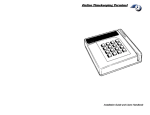
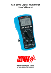
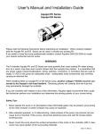
Design and Manufacture of Testing Equipment for Switchgear By Terry Cousins and Luis Valentim, TLC Engineering Solutions Abstract Switchgear is a key component in electrical power systems. It is essential to verify performance after design, manufacture or repair. This paper will discuss a range of automated testing equipment that are used to test switchgear. The test equipment has been designed and manufactured in South Africa in collaboration with switchgear manufacturers and testing authorities. Automated analysis of the measurements as well as archiving of results for future recall and comparison will be presented. Introduction The definition of switchgear includes electrical disconnects, fuses and circuit breakers used to isolate electrical equipment. Circuit breakers are mechanical devices connected to the electrical system, where they must provide a suitable path for the flow of the electric current as well as provide protection and control of the electric circuit by either initiating or stopping the current flow. Circuit breakers design and performance verification requires specific tests to be performed. This paper will present a range of testing systems for circuit breakers from the instrumentation and data acquisition perspective. Circuit Breaker Testing Circuit breakers are designed and manufactured to operate correctly under a range of conditions. These include switching currents up to the rated load, as well as interrupting overload or fault currents several times the rated current. In the event of a malfunction, the circuit breaker as well as parts of the electric system may sustain severe damage. It is therefore essential to have a high degree of confidence in the performance of any circuit breakers. This confidence level can only be attained by years of operating experience, or by extensive testing under conditions that simulate those that are encountered in the field applications. Testing will usually be performed to ensure compliance with a local or international standard. Special tests may also be performed by manufacturers to evaluate new designs. The tests that are common to most circuit breakers include: Mechanical Operation o Performance of the mechanism to open and close contacts o Endurance of the mechanism Electrical Operation o Ability to operate safely with rated loads o Ability to safely isolate overloads and short circuits Mechanical Testing The most basic function of any circuit breaker is to open and close the contacts on command. According to a CIGRE report [1] more than 90% of circuit breaker failures are attributed to mechanical causes. These findings confirm the fact that circuit breakers are primarily mechanical devices that are called upon to perform an electric function. Most of the time circuit breakers remain closed and simply act as electrical conductors. When the breaker performs a protective function, from the combined electrical and mechanical point of view, the contact structure is probably the most essential and critical component. A second and equally important component is the operating mechanism employed to produce the motion of the contacts. A circuit breaker is designed to interrupt a short circuit current. The fault energy is proportional to the square of the fault current times the duration of the fault. The breaker should clear the fault in the minimum time to limit fault damage. This requires that the breaker must operate at a speed greater than a specified minimum speed determined by the design. The current must also be interrupted in such a way that the arc does not re-strike. The interrupting time or breaking time of a circuit breaker has a common definition according to ANSI and IEC. It consists of the time, from the instant the trip coil is energized to the instant of complete interruption of the current flow through the circuit breaker (taking into account the maximum arcing time required for interruption). Note that the contact parting time, as defined by ANSI, is the summation of the relay time plus the opening time. These relationships are illustrated in Fig. 1 below [2]. Fig 1: Interrupting Time Relationships The opening and closing velocities, as well as stroke, or travel distance, are the most important operating characteristics of a circuit breaker. They are dictated primarily by the requirements imposed by the contacts. Opening and closing velocities are important to the contacts in order to avoid contact erosion as well as contact welding. Since contact stroke is synonymous with contact gap, circuit breaker stroke is primarily related to the ability of the circuit breaker to withstand the required operating dielectric stresses. The opening and closing motion curve of a circuit breaker is shown in Fig. 2 [3]. Fig. 2: Circuit Breaker Open and Closing Motion Open / Close Speed Test This test is performed to confirm the key mechanical parameters of the switchgear. This includes the open and close speeds, travel distance and contact closing and parting times. Equipment for performing this test consists of: Computer equipment with application software for performing the test and analysing the results Displacement transducer for measuring the travel of the circuit breaker Continuity measurement for measuring the contact open and closing Control circuit and power supply for energising the trip and close coils Current clamps to measure trip and close coil currents The equipment is shown below in Fig. 3. Fig. 3: Test Equipment for Open / Close Speed Test The test system also requires a power supply to energise the close and trip coils as well as a supply for charging the mechanism. The travel measurement is obtained by connecting a linear displacement transducer to the contact mechanism. The output of this transducer is then calibrated to correspond with the distance moved by the contacts. A typical graphic display from the test is shown in Fig. 4. Fig. 4: Open / Close Speed Trace The upper trace is the travel. The centre three traces are the continuity of the contacts. This example shows severe contact bounce when the contacts close. These results are then automatically analysed by the computer software and a report is produced similar to the report in Fig. 5. Fig. 5: Open / Close Speed Test Analysis Results These results can be printed and are saved to a database for future reference. Short Circuit Testing Short circuit testing is one of the most essential tasks that must to be performed on equipment to verify equipment suitability. It is also an essential tool from the design point of view, as much design knowledge is based on experimental findings and consequently testing becomes the tool that is used for the development of circuit breakers. Short circuit testing presents a challenge, because what must be replicated is the interaction of a mechanical device, the circuit breaker, and the electric system where the switching conditions can vary quite widely depending upon the system configuration and so can the conditions which must be demonstrated by tests. Another challenge has always been the development of appropriate test methods that can overcome the potential lack of sufficient available power at the test facility. One has to consider that the test laboratory should basically be able to supply the same short circuit capacity as that of the system for which the circuit breaker that is being tested is designed. However, this is not always possible, especially at the upper end of the power ratings. A typical test circuit is shown in Fig. 6 below [2]. Fig. 6: Elementary Schematic of Short Circuit Test The test circuit consists of a power source (G) which can be either a specially designed short circuit generator or the system's electric network. For the protection of the supply, a high capacity back-up circuit breaker (BUB) is used for interrupting the test current in the event that the circuit breaker being tested (TB) would fail to interrupt the current. In series with the back-up circuit breaker there is a high speed making switch (MS) which is normally a synchronized switch capable of independent pole operation and of precise control for closing the contacts at a specific point on the current wave. Current limiting reactors (L) are connected in series with the make switch. These are used to limit the magnitude of the test current to its required value. Specially designed test transformers (T) are connected between the test circuit breaker and the power source. These transformers are used primarily to allow for flexibility for testing at different voltage levels, and in addition to provide isolation between the test generator and the device that is being tested. Across the test breaker terminals a bank of transient recovery voltage shaping capacitors (C) is connected. To measure the voltages at least one set of voltage dividers (V) are used. The short circuit current flowing through the test device is measured by means of a shunt (Is). Current transformers can be used especially for the current at the upstream side of the circuit breaker. The test equipment (instrumentation) supplied for the short circuit testing consists of: High Speed Digitiser o Measures voltage and current waveforms up to 5 MS/s with 12 bit resolution o Capture up to 4 million samples Precision Timer o Used to synchronise all the test events to a precise timebase Computer for Data Analysis and Presentation A precision timer was specially designed and engineered for this application [4]. A programmable logic controller (PLC) is used in the test facility to provide the necessary control and safety interlocks. It does not however have a sufficiently accurate timebase to provide for the synchronization of the make switch. Under short circuit conditions the current flowing through the circuit breaker can exceed 100kA and equipment is highly sensitive to the time taken to clear the fault. In order to test circuit breakers it is necessary to provide an exact fault current to ensure the device is not destroyed by the test. The fault current is obtained by connecting the breaker to a known load and switching on and off at a specific point of the 50Hz ac wave. This is illustrated in Fig. 7. Fig. 7: Precision Point-on-Wave Switching with Precision Timer The Precision Timer requirements were as follows: 10 microseconds accuracy in a 20 second timeframe 24 timer channels Independent pulse duration for each channel Absolute or point-on-wave time synchronization Graphical entry of timer parameters The actual design achieves timing accuracies around 2µS. The block diagram of the Precision Timer is shown in Fig. 8 Fig. 8: Precision Timer Block Diagram A graphical user interface was developed to facilitate entry and display of the test sequencing times. This is shown in Fig. 9. Fig. 9: Precision Timer Test Sequencing The waveforms from the short circuit test were acquired by the high speed digitizer and displayed on the computer screen in the control room. For some tests this had to be completed in a minimum time to ensure subsequent tests were performed according to a specific schedule. A typical test waveform is shown in Fig. 10. Fig. 10: Short Circuit Test Sample Waveform A number of automated analysis features are available by selecting an icon on the screen. These include: Relative Measurements Markers STL Peak calculation (STL parameters are specified by the Short-Circuit Testing Liaison Agreement (STLA). This is an Agreement Group of International Certification Bodies concerning the type testing of high voltage electrical power equipment.) STL RMS calculation I2t Integration AC RMS calculation Removal of Mean Export to comma separated text (CSV) Format All the raw data and results can be stored in a database for future reference. A typical three phase calibration test waveform is shown in Fig. 11. Fig. 11: Example Three Phase Calibration Waveform In addition to the short circuit test method described above where fault currents are interrupted, there are several other test methods which involve testing at a specific current to determine the current carrying capacity of the breaker. Earth Leakage Circuit Breaker Testing The earth leakage circuit breaker (ELCB) is primarily used for the protection of human life. It has been found from numerous studies that once they have been introduced, they dramatically decrease the number of fatalities from electric shock [5]. The use of ELCB in buildings is required by law in South Africa (SANS 10142-1: 2003 - Code of practice for the wiring of premises) [6]. The performance of the ELCB is regulated by local and international standards e.g. SANS 767-1 (SABS 767-1), Earth leakage protection units – Part 1: Fixed earth leakage protection circuitbreakers. IEC 1008-1 - Residual Current Operated Circuit Breakers UL 943 - Ground Fault Circuit Interrupters Manufacturers of ELCB need to provide proof of compliance by submitting circuit breakers for testing to testing laboratories. An ELCB Test Unit (instrumentation) was developed for this compliance testing. It consists of: Computer based test sequencer Digitiser Variable Current Source Control Switching Tests basically require the injection of a leakage current into one of the phases. A simplified ELCB test circuit is shown in Fig. 12. Fig. 12: Earth Leakage Test Unit Block Diagram The user interface for the test setup is designed so that any one of the required tests can be performed. All of the results are stored in a database for future reference. A typical test setup screen is shown in Fig 13. The test follows the format of the standards requirement so that all the required tests must be completed on the sample batch. Fig. 13: Earth Leakage Test Unit Operator Interface The equipment is housed in a 19” instrumentation panel as shown in Fig. 14. Fig. 14: Earth Leakage Test Unit Equipment Endurance Testing A useful test to perform on switchgear is a rated load test for an extended period. This is used to determine if any equipment malfunctions and can also be used to evaluate thermal information. A constant current test rig was developed for this test with the following specifications: Used to test circuit breakers up to 400A Programmable constant voltage / current Closed loop control to keep current at required value Detect if any devices trip Record results The testing system consists of a 3.2kW power supply and adjustable transformer which provides the test current. The output is set by a computer system which ensures the output remains within set limits. The computer also saves the measured value and saves the test results to a database. While a temperature recording device did not form part of this test rig, it could be included if required. The constant current supply user interface and results are shown in Fig 15. Fig. 15: Endurance Test Setup Screen Fig. 16: Final Current Adjustment Once the test parameters have been entered, the operator selects the required current and adjusts the variable transformer until the test current is in the green band as displayed in Fig. 16. The computer then regulates the current in a closed loop control until the test is complete. The test can conclude either by successfully reaching the specified end period, or one of the test devices can trip which will result in the failure of the test batch. All results from the test are saved to a test database that can be used for record keeping and results analysis. A sample database screen is shown in Fig. 17. Fig. 17: Test Results Database The test computer equipment is housed in a modular 19” rack mount system shown in Fig. 18. Fig. 18: Endurance Test Panel Conclusion A number of diverse switchgear testing systems have been successfully developed and deployed locally for switchgear manufacturers and testing laboratories. The test equipment design requires close collaboration between switchgear manufacturer, testing laboratory and test equipment supplier. The equipment requirements and standards change over time. The test equipment must be designed to be flexible so as to accommodate future enhancements. References [1] [2] [3] [4] [5] [6] CIGRE SC13, High Voltage Circuit Breaker Reliability Data for Use in System Reliability Studies, CIGRE Publication, Paris, France 1991. Ruben D. Garzon: High Voltage Circuit Breakers, Design and Applications, 2nd Ed, Marcel Dekker Inc., New York, 2002 TM1800 Circuit Breaker Analyzer System User Manual, GE Energy T Cousins: Development of a Precision Timing System for Circuit Breaker Testing, Quantum, November 1999 Viv Cohen: Electrical Shock And Fire Hazard Protection – Conquering The Limitations, Elektron, September 1993. SANS 10142-1:2003 (Ed. 1.1) The wiring of premises Part 1: Low-voltage installations Contact details For further information, contact Terry Cousins, Director, TLC Engineering Solutions on 011 463 3860 or [email protected]