1
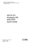
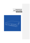
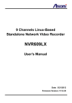
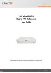
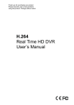
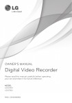
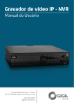
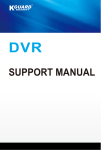
STANDALONE H.264 DIGITAL VIDEO RECORDER USER MANUAL Before usage The User manual is for DVR installation and operation. The User who install the device first or Qualified Personal, before installing DVR, has to read user manual carefully and follow warning instructions avoiding malfunction of operation or product failure. Refer all servicing to qualified service personnel or suppliers while install and set the DVR. Keep these operation instructions handy for future reference. Warnings for safety The user has to keep in mind of followings for safety usage and well-operation. ㆍ Do not shock during installation or Product carried ㆍ Do not expose to shock or vibration. ㆍ Do not move while the product is operating. ㆍ Do not plug out while the product is operating. ㆍ After power off, clean the DVR only dry towel. ㆍ Do not put out Plug code, touch power plug with wet hands. ㆍ Do not place heavy object on power code, it may cause power code damage, occur fire or electric shock ㆍ Install stable place and keep proper temperature, if install the DVR in sealed place, it may cause a fire. . ㆍ Do not install humidity place, electronic hazard, moisture. ㆍ Protect the power cord from being walked on or pinched particularly at plugs, convenience receptacles. ㆍ Recommend to use protect device to prevent failure through blackout or lighting. ㆍ Do not expose direct sunlight and install near radiators, heat registers or other apparatus that produce heat. ㆍ Do not place near flammable spray or any heat source, cause of flammable material, it may cause a fire ㆍ Do not damage, Blend, twist, modified, pull out, heat power code, it may cause damage power code or outlet. ㆍ Do not insert the metals such as a coin, a hair pin, a piece of iron or flammable Material such as a paper, a matchstick, etc. in the DVR, It may cause a fire or an electric shock ㆍ Contact the supplier after turn off the DVR, when odor smoke or smell in the DVR. 2 Approved HDD List Capacity Manufacturer HDD Western Digital 250G Hitachi MODEL Name F/W Ver. WD2500AVVS 63L2BO WD2500AAJS 22B4A0 HDD 250G HDS721025CLA382 SATA HDS721025CLA382 HCS5C1025CLA382 Seagate 320G Seagate HDD 320G SATA Western Digital 500G Seagate Hitachi HDD 500G SATA Hitachi 750G Western Digital ST3250312CS SC13 ST3320418AS CC38 WD5000AVVS 63H0B1 ST3500418AS CC38 ST3500312CS SC13 HCS5C1050CLA382 HDS721050CLA362 HDD 750G SATA WD7500AACS ST31000528AS CC38 ST31000322CS 1TB Seagate HDD 1TB SATA WD10EADS 00L5B1 HCS5C1010CLA382 HDS721010CLA332 1.5TB Seagate HDD 1.5TB ST31500341AS Western Digital SATA WD15EARS Seagate 2TB Western Digital 00Z5B1 ST32000542AS HDD 2TB SATA Hitachi WD20EARS 00Z5B1 HDS722020CLA330 (February, 2011) [Warning] Please use approved HDD avoiding malfunctions of operation, if the user want to use other HDD, Please contact to supplier and check the HDD is available or not. 3 - CONTENTS 1. OVERVIEW ∙ Features ………………………………………………………………………………………………………..……………………….…...……..6 2. INSTALLATION ∙ Package Contents .………………………...………………………….…………………………………………………………….…..…….7 ∙ Part Names and Functions (Front) …………………….………………………………………………………………....….……...8 ∙ Part Names and Functions (Rear) …………………..…………………………………………………………………….….………9 3. SYSTEM OPERATION ∙ Menu Setup ……………….…………………….……………………………………………………………………..………………...…….10 ∙ Icons ……………………….……………………………………………………………………………………………………..……………..…10 ∙ Using Remote Control …………………………………………………………………………………….………………………….…..12 ∙ How to setup Remote ID ……………………………………..…………………………………………………………….…….…....13 4. SYSTEM CONFIGURATION ∙ System Setup ……………….…………………………………………………………………………………..…..……..………………….15 ∙ Time/Date ……………….…………………….……………………………………………………………….………………...…….…….…16 ∙ Password ……………….………………………..…………………………………….……………………………………………….…….….17 ∙ Hard Disk ……………….………………………………….……………………………………………………………………….……..…….17 ∙ Default Setup ……………….…………………..…………………………………………………………………………….…..…….…….19 ∙ Upgrade ……………….………………………………………………………………………………………………………………………....19 ∙ Button Setup ……………….…..………..……………………………………………………………………….……………….….….……20 ∙ RS-485 ……………….……………………………..……………………………………………………………….……………….….….…….21 5. DISPLAY SETUP ∙ OSD ………………..……………………………………………………............................................................................................….22 ∙ Auto Sequence ………………..……….………………..…………………………………………………..……………..…..…………….22 ∙ TV Adjustment ……………….………..…….…………..………………………………………………………………..………..…..……23 6. NETWORK SETUP ∙ IP Address Setup ………………...…………………..………………………………………………………………….…………….…….24 ∙ Web Server ………………..………………………..……………………………………………………………………...………….……….25 4 7. CAMERA SETUP ∙ Camera …………………...…………………….………………………………………………………………………..……..………….…..…26 ∙ PTZ Setting ……………………………..…………………………….….…………………………………………………………….....……26 ∙ Using Pan/Tilt ………………………….……………………….…………………………………………………………………..…....……28 8. RECORD SETUP ∙ Recording Setting …………………..….…………………………..……….……………………………………………………...……….30 ∙ Schedule Record …………………..…….…………………………..……….……………………………………………………..……….31 ∙ Holiday Record ………………….……..........…………………………..……….………………………………………………...……….32 9. EVENT SETUP ∙ Sensor ……………………………………...…..……………………………………………………………………………………….…………34 ∙ Motion Detection …………………..….……………………..………………………………………………………………...……..……34 ∙ Camera Tamper Detection ……………………...……………….…………………………………………………..…………....……36 ∙ Event Action …………………..……………………………………………………………………………………….…………………..…..36 10. SEARCH SETUP ∙ Search ………………….…………………………………..…………………………………………………………….…………………..……41 ∙ Calendar Search ………………….…………………..…………………………………………………………….…………………..……41 ∙ Date/Time Search ………………….………………………..………………………………………………………………………………43 ∙ Event Search …………………..…..………………………..…………………………………………………………………………….……44 ∙ Play Control ………………….……………..………………..……….………………………………….…………………….……….…......45 ∙ Audio …………………...…………………………..……….………………………………………………………….……………….……......46 11. BACKUP SETUP ∙ Bckup …………………………………………………………..……………………………………………….……………………….…………47 12. APPENDIX ∙ Specification ……………………………...……………..…………………………………………………………….……………....………52 ∙ Product Warranty ………………………………………...………………………………………………………………………………….53 5 1. OVERVIEW Features The DVR employs H.264 video encoding 4 channel input; audio encoding for 4 channels while simultaneously supports hard disk recording and playback. The DVR has mirroring function, mirroring HAD record and display regardless of unexpected physical shock or damage. Main Features ㆍControl Pan / Tilt by using Mouse or Joystick ㆍ2 USB ports for easy back-up ㆍODD Back up available (Option) ㆍFull Frame transfer under GIGA network available ㆍMulti language ㆍDynamic IP Internet access available ㆍDual-Stream network transfer available ㆍSupport D1 resolution each channel independently ㆍCMS software ㆍProvide software for Smart phone, IP viewer, Network Viewer Application √ Bank, ATM unit, Supermarket, Convenient store and other public places. √ Private homes, Apartment, Jewelry shop, Commercial compound and other places where it needs anti-theft surveillance system. √ Warehouse, Production line and other places where evidence is needed after any event happened and to analyze the situation. √ Where to monitor sites remotely 6 2. INSTALLATION Package Contents Please unpack the product, and place the product on a flat place or in the place to be installed. Please check the following contents are included in addition to the main unit. HDD Fixing Screws (5pcs) Batteries for CD Remote Control (AAAX2) User Manual DIGITAL VIDEO RECORDER Adaptor Power Cable Remote Controller 7 Part Names and Functions (Front) (Front Panel) [1] Sequence of 4-Split and Auto Sequence in order by pressing more than 3 seconds [2] USB Connection Port [3] Channel Keys [4] Remote Control Receiver LED [5] LED Indicator (Power/REC/HDD Status/Network) [6] Buttons for Direction / Select / Play / Pause [7] MENU [8] PTZ Control [9] Search [10] Audio [11] Emergency Recording [12] Backup 8 Part Names and Functions (Rear) [1] Audio Out: Output Port for the Audio Signal [2] Audio In (1~4): Input Port for the Audio Signal [3] Video In: Input Port for composite Video Signal [4 Video Out: BNC Type of Output Port for the composite Video Signal [5] VGA: Output Port for VGA Video Signal [6] NETWORK: Network Connection Port [7] Alarm / Sensor / RS-485 (When you connect to PTZ Cameras) (Refer to the detailed settings in each part in the manual.) [8] Power: Port to be connected to DC 12V/3.5A Power Source 9 3. SYSTEM OPERATION Menu Setup The MENU can be operated by pressing the Front Menu Button or using the Remote Control. ☞ Using Front Buttons 1) Press the “MENU” Button. 2) Use the Direction Keys and to select the MENU and “MENU” Button for “ESC” ☞ Using Remote Control - Press “SETUP” Button. ☞ Using Mouse 1) Right-click any area of the screen and the MENU will pop up. 2) Left-click to enter the MENU. Icons [1] The Icons indicate the Status in Live Mode. 10 [2] CAM ID: Camera ID will be shown same as the below picture. [3] Recording Status Icon REC Video Loss Motion Detected Sensor Detected 11 [4] Status Bar • Date / Time • “ER” : Emergency Recording / “SR” : Schedule Recording • Network Connection / Screen Lock • Shows the available capacity of the Hard Disk and “OVERWRITE” when you write again above the current data. Using Remote Control You can control all the functions with this Remote Control. It’s easy to carry and available to operate Multi DVRs’ with 1 Remote Control. 12 [1] ID: If you want to control Multi DVRs’ in 1 Remote Control, put this “ID” to select each number. [2] SPLIT: Displays the selected “Split Mode” same as you put in the “MENU”. (Same function as “QUAD” in the Front panel.) [3] BACKUP: To use USB MEMORY STICK for BACKUP [4] AUDIO: Turns AUDIO ON/OFF and you can select each channel. [5] SEQ (Sequence): Displays “Auto Sequence” and the Channels automatically you set. [6] PTZ: To control Pan/Tilt/Zoom Camera [7] SEARCH: To search the Recording Data [8] Number (0 ~ 10): Used as the numeric input keys (to display a single channel or put the password) 13 [9] SETUP: Displays “SETUP MODE” [10] Up/Down/Left/Right/Play/Pause/Enter: Moves the cursor up/down/left/right, runs the selected Menu, and controls the Play/Speed/Pause during the Play. [11] REC: Starts or ends the live/scheduled Recording and Emergency Recording. How to setup Remote ID To control Multi DVRs in 1 Remote Control, you have to set each ID before using it. If the ID between the DVR and Remote Control is different, you cannot use it correctly. [1] Changing the Remote ID 1) Check the Remote ID in ‘SYSTEM” Menu. 2) Menu System Information Remote ID (0 ~ 99) * The Default Setting is “0”. If you control Multi DVRs in only 1 Remote Control, put different ID Numbers. * Use the Remote Control only when you change the ID. If you use the Front Keys, the ID is not changed correctly. 14 3) Press the “ID” Button on the Remote Control and then you can see the menu to change the DVR ID. (Refer to the above picture.) √ ID : displays the current Remote ID of the selected DVR. √ “0” : Input the same ID Number with Number Keys and then press “Confirm” to save it. 15 4. System Configuration System Setup [1] Remote ID: Assign the ID of Remote Control so that user can separately control Multiple DVRs with 1 Controller. (ID Range: 0 ~ 99) [2] Mouse Sensitivity: Changes the Sensitivity Level for the Mouse for user’s convenience. (Basic: 1, to increase the reaction speed: 1 < 2 < 3) [3] Language: Selects your Language. [4] Version: Shows S/W, H/W, N/W Versions [5] Health: Displays the status of its Storage • Hard Disk1 : The temperature of the HDD • USB1 /USB2: The status of the Connection of USB Port at the Front Panel [6] Video Detect Mode: Selects a Video Signal (NTSC/PAL) [7] Video Mode: Displays correct Video Signal Format. [8] Web code: DDNS ID when you control the DVR remotely with DDNS Connection [9] Mac Address: Its own Mac Address. 16 Time/Date [1] Time: Set the Time [2] Date: Set the Date [3] Date Format: Year (YYYY), Month (MM), Day (DD) [4] Day Light Saving Time (Summer Time): If you select “Yes”, the time makes 1 hour earlier than the GMT of its time zone. [5] Time Server : Synchronizes the Time automatically with Time Server Service. √ Time Server : Input the URL of the server (Default : kr.pool.ntp.org ) √ synchronize Period : Selects the period to synchronize the Time between the DVR and Server ㅇ Power On : Sync when the Power On. ㅇ 12Hour : Sync every 12 Hours. ㅇ 24Hour : Sync every 24 hours. ㅇ Off : Not use to Sync. [4] Time Zone: Selects a GMT Zone [5] Apply : Saves the Time / Date 17 Password [1] ID: You can use till 8 IDs at most. (Admin ID & User ID: 1~7) [Note] Default ID: “11111111” [2] Function: You can set the permissions of each user to access the below menus. ㅇ Configuration ㅇ Hard Disk ㅇ Search ㅇ Back up : ㅇ PTZ Setting ㅇ REC Key at the Front Panel ㅇ Camera Hard Disk This HDD Management is closely connected to the “Record” Menu. It may cause the malfunctions if the setup is wrong so make sure that it is set correctly. 18 [1] Hard Disk List: shows the HDD information including External Disks and supports Format. ㅇ Hard Disk1 : the Capacity of Hard Disk Drive ㅇ USB1 : the Capacity of external USB1 connected ㅇ USB2 : the Capacity of external USB2 connected ㅇ Erase Data : Selects and format the Disk you choose [2] Total: Displays the capacity of HDD (Total Size / Used Size) [3] Erase Data: Formats the data for selected disks ㅇ Main Disk : Deletes the datas in Main Disk. ㅇ Mirror Disk : Deletes the datas in Mirror Disk. [4] Auto Delete : Keeps the recorded Datas in HDD only for specified period (Range : 1~120 days). The datas before this perioed will be deleted automatically. [5] Advanced : Selects the Hard Disk to “Main Disk” or “Mirror Disk”. After choosing one of them, press “Apply” to save this option. 19 Default Setup [1] Default Setup : Initializes the system excluding major configurations like Network, Password, Recording Setup. [2] Factory Setup : Initializes all the system to the factory default. Upgrade [1] USB Upgrade : To upgrade the firmware, you can use USB Memory Stick by connecting it to 20 the Front Port 1 or 2. Firmware USB Memory Stick [NOTES] Do not turn off the power or remove the USB stick during this backup. It may cause the malfunctions and please contact us if it is stopped without any message. [2] Configuration BACKUP : Back-up DVR configuration in USB memory stick. [3] Configuration LOAD : Down load desired DVR configuration in other DVR. Button Setup This makes the screen be locked automatically after selected time is passed, You have to log in again if the screen is locked for this Setting. Selecting Time : 10 sec/ 30sec/ 1 min/ OFF) 21 RS-485 This DVR supports RS-485 Communication to control the PTZ Cameras or Control Keyboards. You can use RS-485 Communication to control P/T/Z when you connect PTZ Cameras or Keyboards. It may be differnt for each brand so refer to those manuals not to be confused. √ Baud rate / Parity / Stop bit : Select the functions with the manual of the products’ manual you want to connect. 22 5. DISPLAY SETUP OSD You can select the options which are displayed in the screen. [1] Camera Title: Gives the name of each camera. [2] Status Bar : displays the Status for some information at the below. [3] Multi screen Border : Divides the Screen Borders [4] Login Menu : shows the “Login Menu” after rebooting the DVR. • Booting UnLock : login automatically. • Booting Lock : displays the “Login Menu” to start the DVR. [6] Alphablending : Selects the level of transparency for the backgrond of the Menu. Auto Sequence Auto Sequence makes the screen be switched automatically accoring to the selected “Display Time”. 23 ▷ Auto Loss Skip : If there’s no video input, this menu is not applied. ▷ Display Time : Selects the Display Duration for each channel. (1sec ~ 30sec) TV Adjustment [1] Monitor : Select the ratio of the Monitor. ( Currently, the Monitor with 4:3 is available only.) [2] Icon : The OSD Posion is changed accoring to the size of a Monitor you use. • Small : for a small monitor • Normal : for a normal sized monitor • VGA : for a LCD Monitor [NOTES] The mode “Small” and “Normal” is available in CRT Monitor. 24 6. NETWORK SETUP IP Address Setup It provides networked monitoring of Live Screen from a remote place and you have to setup some infromation to use correctly. Please check whether your Network Connection Mode is Dynamic IP(DHCP) or Static IP before setting. [1] DHCP : “ON” for Dynamic IP Users / “OFF” for Static IP Users [2] IP Address : The users for “Dynamic IP” don’t need to set it but for “Static IP Users” have to input the Addresses same as below examples. If the Network Connection is with “Status IP”, ask the information to Network Service Provider. [Examples] • IP Address : 61.250.152.050 • Subnet mask : 255.255.255.000 • Gateway : 61.250.152.001 • DNS Address : 164.124.101.002 [3] DDNS Address : It’s for the user of “Dynamic IP” so do not change it. ( Factory Default : 115.68.7.22 ) [4] Use Port : DVR Port is “2400” [NOTES] If the user for “Dynamic IP” uses the Router, make a PORT FORWARDING. For this setting and detailed functions, refer to its manual. 25 Web Server This DVR includes Built-in Web Server so you don’t have to install additional program for Networked Monitoring.. If you put IP Address only in Local Network, you can control the DVR remotely. [1] On/Off : “On” – Use the Networked Monitoring in Local Network “Off” – Use the Networked Monitoring through Web. [2] Use Port : Connection Port for Remote Control [Example] IP Address : 61.250.157.50 / Port : 2001 http://61.250.157.50:2001 (Enter) [NOTES] When you connect the DVR with the Web Server through the WAN, you have to make “PORT FORWARDING” for both Port Numbers of Web Server and using DVR Port. 26 7. CAMERA SETUP Camera Set the name of each camera. You can input the names with the Keyboard on the screen after choosing the Channel. PTZ Setting PTZ Settings menu for PTZ Setup 27 [1] Channel : Selects the channel you want to connect. [2] ON/OFF: ON: Use PTZ / OFF: Do not use PTZ. (Default: On) [3] MODEL: Selects the Model Name or its Protocol. [4] ID : Selects its ID (Range : 0~255 / refer to the manul for each brand you use.) Advanced Advanced Menu is available only for the models which have detailed PTZ Setup menus. [1] Reverse Control(Pan) : Set the direction of its working reversely. (Left, Right) [2] Reverse Control(Tilt) : Set the direction of its working reversely (Up, Down) [3] Touring Mode • Preset Touring : Selects when you control it through the DVR. [4] Preset Touring Setup 28 The touring number is selectable from 1 to 16 and works in order. [1] Touring Number: Selects the order [2] Preset Number: Selects the Preset Number saved before. [3] Touring Interval (/SEC): Selects the Touring Dwell Time. [NOTES] Selecting the Protocol for PAN/TILT When you select the Protocol, its name is registered in the Name of Camera or Protocol. Using Pan/Tilt You can select this menu same as below. • Using Mouse : Right-click any are of the screen and select the PTZ. • Using Remote Control : Click the PTZ. (1) PTZ Control by Front Panel • Pan/Tilt Control : Press the “MENU” Button at the Front Panel (or Right-click of the Mouse) and then you can see the above menu to control it. • Selecting the Menu for Pan/Tilt Control Menu ㅇ Pan Tilt : Control it with the Direction Keys from the Remote Control. 29 ㅇ Preset : Input the Preset Number to move or save and then Save ( (Moves to select Preset) ) it. (Saves the Preset) ㅇ Tour : Moves the Saved Presets automatically in order. ㅇ MENU : shows the “Pan/Tilt Menu” ㅇ Channel : available to change the Pan/Tilt Channels in Multi-channels. Select the “Channel” Menu and then move to other channels with direction keys. ㅇ Exit : Ends the PTZ Mode. 30 8. RECORD SETUP Record Setting The Recording Setup is to select the detailed values like Recording Resolution,Frames and so on. The Recording File Size can be bigger according to this setting so be careful to set it. [1] Channel: Selects the Channel. [2] ON/OFF: Checks the selected channel to be recorded or not. [3] Resolution : Sets the Recording Resolution. [4] Quality : Sets the resolution of recorded screen. ( HIGHEST > HIGH > NORMAL > LOW > LOWEST) [5] Speed : Selects the Recording Frames. [6] Post-Recording : Sets the Duration Time for Recording after the Event happens. [7] Record Audio : Sets the Audio ON/OFF [8] Total rec Framerate : Shows the sum of Recording Frame Rates for each channel. 31 Schedule Re Schedule Record Makes your reservation on a date, time, and channel to schedule the recording per 30 minutes. █ N (Grey) : No record █ C (Green) : Continuous Record █ M (Blue) : Motion Detected Record █ S (Red) : Sensor Detected Record █ M+S (Yellow) : Motion and Sensor Detected Record 1. Select the Channel. 2. Once you select the Date and Time, choose the one of above options. It moves from “N” to “M+S” in order. (N C M S M+S) 3. After selecting other Date or Time, press “Confirm” and then the Event Color is changed. √ Clear : deletes the schedule of selected channel. √ Channel to Copy : Copies the current Schedule Record onto the selected channel. (Press “SETUP” to escape the previous step.) √ All Ch to Copy : Copies the current Schedule Record onto all the channels 32 Holiday Record Different Record Setting can be applied to each holidays. [1] You can select the Holiday Record with 7 differnt types. After selecting the type (H1 ~ H7), drag with mouse or use the direction keys with Remote Control. [2] Slescts “Holiday” in the Menu and the Holiday Type (H1 ~ H7) in the Calendar. 33 Whenever you click the date, the color is changed, which means the different types of its setting “H1 ~ H7”. 34 9. EVENT SETUP Sensor You can set the Sensor’s Input condition and related camera. [1] Sensor Input : Selects a channel to be connected to the sensor. [2] On/Off : Selects the use of this Sensor. [3] Input Type : Selects the Sensor Input Type • N/Open (NORMAL OPEN) : Sensor is opened. If the sensor is closed, it generated alarm. • N/Close (NORMAL CLOSE) : Sensor is closed. If the sensor is open by interruption, it generates alarm. [4] Related Camera : Selects the camera to be connected to the sensor and Multi-selection is available. Motion Detection You can set the target detection region and motion. You can select the Detection Area and Sensitivity to record the event when the Motion Detection happens. 35 [1] Channel : Selects the Channel to use Motion Detection. [2] On/Off : Selects the Motion Detection Use. [3] Sensitivity: Selects the Sensitivity of Motion Detection. Use the Value after testing this Sensitivity in advance before saving it. [4] Detection Area : Sets the Motion Detection Area. Use the direction keys to set the areas and press “Enter” button. • MD selected area : Pink Color • MD non-selected area : No color • If the motion is detected, the area is with green. 36 [APPLY TO ALL] Use the following keys to “APPLY TO ALL”. “1” Button : Select ALL “2” Button : Release ALL [Using Mouse] Right-click from the Starting Position and drag it to the finishing position for Motion Detection Area. Camera Tamper Detection When the image is detected with too dark or bright, it recognizes as an event. Normally, it detects the situation when the door/window is open or the camera is blocked with some materials. [1] Channel: Selects the use of Camera Tamper Detection [2] White Detection: Detects the bright situation [3] White Sensitivity: Selects the sensitivity of brightening [4] Black Detection: Detects the Dark situation [5] Black Sensitivity: Selects the sensitivity of darkness. Event Action You can set the event recording options for Motion, Sensor, Video Loss, Black Detection, and White Detection. 37 [1] Motion : Sets PTZ, Popup, Relay Out, and Buzzer when the Motion is detected. • Channel : Selects a channel to apply. • Preset Channel :Selects a Preset Camera to apply when Event happens. • Preset Number : Selects a Preset Number to move. • Popup Channel : Selects the use of Popup . • Popup Duration : Sets the Duration to keep the Popup window. • Relay Out : Selects the Alarm Out. • Relay Duration : Sets the duration of alarm signal. • Internal Buzzer: Selects the use of Internal Buzzer on the DVR [2] Sensor : Sets PTZ, Popup, Relay Out, and Buzzer when the Sensor is detected. 38 • Channel : Selects a channel to apply. • Preset Channel : Selects a Preset Camera to apply when Event happens. • Preset Number : Selects a Preset Number to move. • Popup Channel : Selects the use of Popup . • Popup Duration : Sets the Duration to keep the Popup window. • Relay Out : Selects the Alarm Out. • Relay Duration : Sets the duration of alarm signal. • Internal Buzzer: Selects the use of Internal Buzzer on the DVR [3] Video Loss : Sets PTZ, Popup, Relay Out, and Buzzer on a camera disconnection, which causes a video loss. 39 • Channel : Selects a channel to apply. • Preset Channel : Selects a Preset Camera to apply when Event happens. • Preset Number : Selects a Preset Number to move. • Popup Channel : Selects the use of Popup . • Popup Duration : Sets the Duration to keep the Popup window. • Relay Out : Selects the Alarm Out. • Relay Duration : Sets the duration of alarm signal. • Internal Buzzer: Selects the use of Internal Buzzer on the DVR [4] Black Detection : Sets PTZ, Popup, Relay Out, and Buzzer when it detects the darkness. • Channel : Selects a channel to apply. • Preset Channel : Selects a Preset Camera to apply when Event happens. • Preset Number : Selects a Preset Number to move. • Popup Channel : Selects the use of Popup . • Popup Duration : Sets the Duration to keep the Popup window. • Relay Out : Selects the Alarm Out. • Relay Duration : Sets the duration of alarm signal. • Internal Buzzer: Selects the use of Internal Buzzer on the DVR [5] white Detection : Sets PTZ, Popup, Relay Out, and Buzzer when it detects the Brightness. 40 • Channel : Selects a channel to apply. • Preset Channel : Selects a Preset Camera to apply when Event happens. • Preset Number : Selects a Preset Number to move. • Popup Channel : Selects the use of Popup . • Popup Duration : Sets the Duration to keep the Popup window. • Relay Out : Selects the Alarm Out. • Relay Duration : Sets the duration of alarm signal. • Internal Buzzer: Selects the use of Internal Buzzer on the DVR 41 10. SEARCH SETUP Search You can perform the Search for recorded data by the time, Motion Detection, Sensor Detection, and so on. [1] Accessing the Search Menu: Press the “Search” Key on the Front Key, Remote Control, and the right button of the Mouse. [2] Select Search Mode • Calendar Search : Select Calendar to Search / easy to search the recording files if you don’t know the exact Date/Time • Date/Time Search: Select Date/Time to Search • Event Search : Select Event to Search • Go to First : Searches the first recorded data on HDD. • GO to Last : Searches the last recorded data on HDD. Calendar Search It searches the recorded data from the Calendar. [1] If there’s any recorded data on DVR, it shows red on the date. You can select other dates by searching” Y/M/D” with the direction keys. 42 [2] You can see the graph, which shows the Channels, Time for recorded data. After selecting the time, press “Enter” button. [3] The recorded data is shown as a graph and select the minutes to Search. This Search is based on Year/Month/Date/Time you selected and it switches the “Play Mode”. 43 Date/Time Search If you know the specific Date/Time, you can search the recorded data directly with the inputs. [1] Record Begin: Shows the beginning time in the recorded data. [2] Record End: Shows the end time in the recorded data. [3] Channel: Selects the channel to search (specific channel or all) [4] Play Begin: inputs the Time to search. [5] Play: Clicks “Play”. 44 Event Search It searches the Event in the selected date. [1] Selects the disk to search. [2] Day: Selects the day to search. [3] Channel: Selects the channel to search. [4] Event Type: Selects the type of Event to search. (MD/Sensor/Video Loss/System/All) [5] Search: Clicks ‘Search” if you finish selecting the above options to search. [6] It shows the list of the Event you selected and then choose one of them to play. 45 Go to first / Go to last It searches the first or last data from the recorded data in the HDD. Play Control Description of Search Buttons Using Mouse Using the Front Keys [1] Play [6] Fast Rewind [2] Pause [7] Audio On during Play [3] Stop [8] Calendar Search during Play [4] Step Rewind [9] Mark In/Out : [5] Fast Forward Mark In: During the playback, the backup starts by clicking this button. Mark Out: During the playback, the backup ends by clicking this button again. You can find this file in the Backup Menu. 46 Audio You can use the Audio during the Live View or Playback. [1] Opening the Menu: Click the “AUDIO” button on the Remote Control or right-click any area on the Mouse in Live or Playback. [2] Mode Selection • OFF : No Audio Use • CH1 : Audio Out only for CH1 • CH2 : Audio Out only for CH2 • CH3 : Audio Out only for CH3 • CH4 : Audio Out only for CH4 • Auto : Audio Out only for the selected channel • Volume Control : More bars, getting louder 47 11. BACKUP SETUP Backup You can backup the desired data to a connected device. After connecting the USB into the DVR, press the “BACKUP” button on Remote control or rightclick of the Mouse to find the “POP-UP MENU BACKUP”. [1] Select the connected device. If it’s recognized normally, it shows the capacity of the device with the message “XXX MB”. [2] Select the date to backup the data. 48 [3] Double-click the time. [4] Select the minutes. If you click “--------“ below, the time is input automatically. 49 [5] Input the end-time. • If the end-time is same hour from the starting time, click the minutes and then move to “-------“ below. The time will be shown automatically. • If the end-time is different hour from the starting time, press the “MENU” button to moves to the previous step. After input the differnt hour and minute, click “-------“ below for automatic input. [6] Camera : Selects the channel for backup the data. (selected channel is with red.) [7] Backup Start : Click “Backup Start” after finishing all the setup. 50 It shows “Backup Size / USB Capacity” and press “OK” to start backup. [8] If the backup is completely done, you can see the below file in the USB memory stick. Click the file to play the data. [9] Using the Viewer Program. (It plays automatically if you click the backup file.) ① Scroll Bar: Indicates the current playing location from the total playback. ② Open: opens other backup files. ③ Fast Rewind ④ Plays backward ⑤ Step Rewind: Used for backward frame-by-frame search while in PAUSE. ⑥ Pause ⑦ Step Forward: Used for forward frame-by-frame search while in PAUSE ⑧ Play ⑨ Fast Forward 51 ⑩ 4-Split Mode ⑪ 9-Split Mode ⑫ 16-Split Mode ⑬ Captures current image ⑭ Converts into AVI File. If you want to convert the file into AVI File during the Playback in any channel, please click the scroll bar for the Start Time and End Time. After checking the time in the below bar, press the ‘AVI” Button. You can backup this data directly to other device. ⑮ Audio Output buttons: Clicks the Channel Buttons you want to use Audio. 52 11. APPENDIX SPECIFICATION ITEM Video 4CH Video format NTSC/PAL Video inputs 4CH Compression H.264 Video outputs Composite (1) , VGA (1) Playback Record Split / Full screen Speed NTSC : 120fps, PAL : 100fps Frame D1 (30 fps) / Half D1 (60 fps) / CIF (120 fps) Event Continuous, Schedule, Motion, Sensor Audio In/Out 4/1 Alarm In/Out 4/1 Network Communication Other LAN [10/100, Ethernet (RJ45)] CODEC H.264 ( Dual Codec) Protocol TCP/IP, DHCP Remote access CMS, Web browser, Smart Phone App. P/T/Z control Yes(RS-485) Backup USB Pen Drive USB 2.0 support 2 ports HDD Max. 1 x internal HDD Temp. 0℃ ~ 40℃ Power supply DC 12V 3.5A, Adapter Dimension 338mm(W) x 58mm(H) x 220mm(D) Unit weight 2.0Kg 53 Product Warranty This unit has thoroughly been tested and passed on quality control& quality assurance. Based on the warranty, If this unit malfunctions during normal use, you will be guaranteed to get your item repaired free of charge under joint agreement based on the warranty. [Tips on warranty]. ■ Check out the Warranty first. ■ Check the item again what is wrong with it and contact the seller of this unit. [Warranty details] ■ In only case the unit malfunctions during normal operation, the unit can be repaired for free but within a year from the date of your purchase. ■ Repair cost and service charge will be requested in the following cases,. 1. Failure or damage incurred by user. 2. Failure or damage incurred by natural disaster. 3. Failure incurred by user who doesn’t abide by the operation manual. 4. Problem incurred In case appointed power supply (voltage, frequency) is not used. 5. In case user requests consumable parts. 6. In case nontechnical expert changes contents of the unit or damages. ■ Failure of goods out of warranty(1year) cannot be fixed for free but it will be repaired if you are willing to pay for the parts or service.. Product Warranty Item Number Serial Number Purchasing place Date of Purchase Warranty period Name Customer Address ▷ This Warranty can’t be reissued. ▷ When purchasing this unit, please let the seller fill in the blanks above. ▷ If you want to get your items repaired for free, please hand this over. 54 ■ For safe use of system and to prevent product failure or accident, please read this manual carefully before use. ■ The manual includes “Product Warranty”. Be sure to keep it handy for later reference. 55