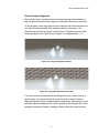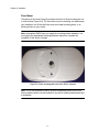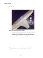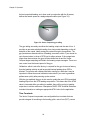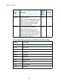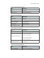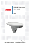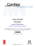
1
Manual
True Heading
Vector Compact.
Rev. 1.0
140918
This device complies with part 15 of the FCC Rules. Operation is subject to the following two conditions:
(1) This device may not cause harmful interference, and
(2) this device must accept any interference received, including interference that may cause undesired operation.
Copyright Notice
Copyright Hemisphere GNSS, Inc. (2014). All rights reserved.
No part of this manual may be reproduced, transmitted, transcribed, stored in a retrieval system or translated into any
language or computer language, in any form or by any means, electronic, mechanical, magnetic, optical, chemical, manual
or otherwise, without the prior written permission of Hemisphere GNSS.
Trademarks
Hemisphere GNSS®, the Hemisphere GNSS logo, COASTTM, PocketMAXTM, Crescent® and VectorTM are proprietary
trademarks of Hemisphere GNSS, Inc. Other trademarks are the properties of their respective owners.
Patents
Hemisphere GNSS products may be covered by one or more of the following patents:
U.S. Patents
6111549
6876920
6397147
7142956
6469663
7162348
6501346
7277792
6539303
7292185
6549091
7292186
6711501
7373231
6744404
7388539
6865465
7400294
7400956
7429952
7437230
7460942
7689354
7808428
7835832
7885745
7948769
8000381
8018376
8085196
8102325
8138970
8140223
8174437
8184050
8190337
8214111
8217833
8265826
8271194
8307535
8311696
8334804
RE41358
Australia Patents
2002244539
2002325645
2004320401
Other U.S. and foreign patents pending.
Notice to Customers
Contact your local dealer for technical assistance. To find the authorized dealer near you:
True Heading AB
Vendevagen 90
S-182 32 Danderyd
Phone: +46(8)6222660
[email protected]
www.trueheading.se
Technical Support
If you need any technical suppoort, please contact True Heading at the above address.
- BLANK PAGE -
Vector Compact User Guide
Vector Compact Contents
Chapter 1
Introduction
Overview . . . . . . . . . . . . . . . . . . . . . . . . . . . . . . . . . . . . . . . . . . . . . . . . . . . . 2
Parts List . . . . . . . . . . . . . . . . . . . . . . . . . . . . . . . . . . . . . . . . . . . . . . . . . . . . 3
Chapter 2
Vector Compact Installation
Mounting Location . . . . . . . . . . . . . . . . . . . . . . . . . . . . . . . . . . . . . . . . . . . . . 6
GPS Reception . . . . . . . . . . . . . . . . . . . . . . . . . . . . . . . . . . . . . . . . . . . . . . . 6
Vector Compact Environmental Considerations . . . . . . . . . . . . . . . . . . . . . . 6
VHF Interference. . . . . . . . . . . . . . . . . . . . . . . . . . . . . . . . . . . . . . . . . . . . . . 7
Mounting Orientation . . . . . . . . . . . . . . . . . . . . . . . . . . . . . . . . . . . . . . . . . . . 9
Vector Compact Alignment . . . . . . . . . . . . . . . . . . . . . . . . . . . . . . . . . . . . . 11
Mounting Options. . . . . . . . . . . . . . . . . . . . . . . . . . . . . . . . . . . . . . . . . . . . . 12
Vector Compact Dimensions . . . . . . . . . . . . . . . . . . . . . . . . . . . . . . . . . . . 12
Cable Considerations . . . . . . . . . . . . . . . . . . . . . . . . . . . . . . . . . . . . . . . . . 14
Flush Mount . . . . . . . . . . . . . . . . . . . . . . . . . . . . . . . . . . . . . . . . . . . . . . . . 15
Pole Mount . . . . . . . . . . . . . . . . . . . . . . . . . . . . . . . . . . . . . . . . . . . . . . . . . 17
Powering and Connecting to the Vector Compact . . . . . . . . . . . . . . . . . . . . 20
Power Considerations. . . . . . . . . . . . . . . . . . . . . . . . . . . . . . . . . . . . . . . . . 20
Electrical Isolation . . . . . . . . . . . . . . . . . . . . . . . . . . . . . . . . . . . . . . . . . . . . 20
NMEA 2000 Port . . . . . . . . . . . . . . . . . . . . . . . . . . . . . . . . . . . . . . . . . . . . . 21
Contents
Chapter 3
Operation
GPS Overview . . . . . . . . . . . . . . . . . . . . . . . . . . . . . . . . . . . . . . . . . . . . . . 24
GPS Operation . . . . . . . . . . . . . . . . . . . . . . . . . . . . . . . . . . . . . . . . . . . . . . 24
Differential Operation . . . . . . . . . . . . . . . . . . . . . . . . . . . . . . . . . . . . . . . . . 25
Vector Compact Overview . . . . . . . . . . . . . . . . . . . . . . . . . . . . . . . . . . . . . 26
Supplemental Sensors . . . . . . . . . . . . . . . . . . . . . . . . . . . . . . . . . . . . . . . . 26
Time Constants . . . . . . . . . . . . . . . . . . . . . . . . . . . . . . . . . . . . . . . . . . . . . 29
Watchdog . . . . . . . . . . . . . . . . . . . . . . . . . . . . . . . . . . . . . . . . . . . . . . . . . . 29
Common Commands and Messages . . . . . . . . . . . . . . . . . . . . . . . . . . . . . 30
Warranty Notice . . . . . . . . . . . . . . . . . . . . . . . . . . . . . . . . . . . . . . . . . . . . . . . . . . . . 50
Vector Compact GPS Compass User Guide
Chapter 1: Vector Compact Introduction
Overview
Parts List
1
Chapter 1: Introduction
Overview
The True Heading Vector Compact GPS Compass is based upon Hemisphere
GNSS’ exclusive Crescent® and Crescent Vector™ II technology.
The Vector Compact is a complete GPS compass and position system in a single
enclosure that requires a standard NMEA 2000 cable connection. With NMEA
2000 support and ease of installation, the Vector Compact is the perfect solution
for marine-based applications.
The Vector Compact is an integrated system that houses the following:
•
Crescent and Crescent Vector II technology
•
Dual integrated GPS antennas
•
Power supply
•
Single axis gyro
•
Tilt sensor on each axis (X and Y axes)
The gyro and tilt sensors are present to improve system performance and to
provide backup heading information in the event that a GPS heading is not
available due to signal blockage.
Crescent Vector II technology supports multiple RF front ends - enabling tighter
coupling of measurements from separate antennas for use in heading-based
products. Users will achieve excellent accuracy and stability due to Crescent’s
more accurate code phase measurements, improved multi-path mitigation, and
fewer components.
The Vector Compact’s GPS antennas are separated by 13.5 cm between their
phase centers, resulting in better than 2° rms heading performance. The Vector
Compact provides heading and position updates of up to 10 Hz and delivers
position accuracy of better than 1.0 m 95% of the time when using differential
GPS corrections from Space Based Augmentation Systems (SBAS).
The Vector Compact also features Hemisphere GNSS’ exclusive COAST™
technology that enables Hemisphere GNSS receivers to utilize old differential
GPS correction data for 40 minutes or more without significantly affecting the
position quality. The Vector Compact is less likely to be affected by differential
signal outages due to signal blockages, weak signals, or interference when using
COAST.
2
Vector Compact GPS Compass User Guide
If you are new to GPS and SBAS, refer to the GPS Technical Reference for further
information on these services and technologies before proceeding.
The GPS Technical Reference is available from True Heading AB.
Please contact us at: [email protected]
Parts List
Note: The Vector Compact’s parts comply with IEC 60945 Section 4.4: “exposed
to the weather.”
Table 1-1: Parts list for Vector Compact
Part Name
Qty
Part Number
Vector Compact GPS Compass (NMEA 2000)
1
804-0128-0
Screw Housing Caps
2
675-0173-0
Mounting Screws
2
675-1199-000#
Mounting Base
1
676-0035-0
Mounting Nut
1
676-1021-000#
Screw Housing Cap O-Rings
2
681-1066-0
3
Chapter 1: Introduction
- BLANK PAGE -
4
Vector Compact User Guide
Chapter 2: Vector Compact Installation
Mounting Location
Mounting Orientation
Mounting Options
Powering and Connecting to the Vector Compact
Connecting the V104 to External Devices
5
Chapter 2: Installation
Mounting Location
This section provides information on determining the best location for the Vector
Compact.
GPS Reception
When considering where to mount the Vector Compact, consider the following
GPS reception recommendations:
•
Ensure there is a clear view of the sky available to the Vector Compact
so the GPS and SBAS satellites are not masked by obstructions that
may reduce system performance.
•
Since the Vector Compact computes a position based on the internal
GPS antenna element, mount the Vector Compact where you desire a
position with respect to the GPS antenna (located on the side of the
recessed arrow on the underside of the enclosure).
•
Locate any transmitting antennas away from the Vector Compact by at
least several feet to ensure tracking performance is not compromised,
giving you the best performance possible.
•
Make sure there is enough cable length to tie into the NMEA 2000
backbone of the vessel.
•
Do not locate the antenna where environmental conditions exceed those
specified in Table B-5 on page 43.
Vector Compact Environmental Considerations
The Vector Compact is designed to withstand harsh environmental conditions;
however, adhere to the following limits when storing and using the Vector
Compact:
•
Operating temperature: -30°C to +70°C (-22°F to +158°F).
•
Storage temperature: -40°C to +85°C (-40°F to +185°F).
•
Humidity: 100% non-condensing.
6
Vector Compact User Guide
VHF Interference
VHF interference from devices such as cellular phones and radio transmitters may
interfere with GPS operation. For example, if installing the Vector Compact near
marine radios consider the following:
•
VHF marine radio working frequencies (Channels 1 to 28 and 84 to 88)
range from 156.05 to 157.40 MHz. The L1 GPS working center
frequency is 1575.42 MHz. The bandwidth is +/- 2MHz to +/- 10 MHz,
which is dependent on the GPS antenna and receiver design (see next
page).
•
VHF marine radios emit strong harmonics. The 10th harmonic of VHF
radio, in some channels, falls into the GPS working frequency band,
which may cause the SNR of GPS to degrade significantly.
•
The radiated harmonic signal strength of different brands/models varies.
•
Follow VHF radio manufacturers’ recommendations on how to mount
their radios and what devices to keep a safe distance away.
•
Hand-held 5W VHF radios may not provide suitable filtering and may
interfere with the Vector Compact’s operation if too close.
7
Chapter 2: Installation
Before installing the Vector Compact use the following diagram to ensure there
are no nearby devices that may cause VHF interference.
VHF Antenna
1.5 m radius at top
(minimum)
Use these minimum
distances to determine
where to place the Vector Compact
1.0 m radius at base
(minimum)
Figure 2-1: Vector Compact distance from nearby VHF radios
8
Vector Compact User Guide
Mounting Orientation
The Vector Compact outputs heading, pitch, and roll readings regardless of the
orientation of the antennas. The primary antenna is used for position.The primary
and secondary antennas, working in conjunction, output heading, pitch, and roll
values.
Parallel Orientation: The most common installation is to orient the Vector
Compact parallel to, and along the centerline of, the axis of the boat. This provides
a true heading. In this orientation:
•
If you use a gyrocompass, you can enter a heading bias in the Vector
Compact to calibrate the physical heading to the true heading of the
vessel.
•
You may need to adjust the pitch/roll output to calibrate the
measurement if the Vector is not installed in a horizontal plane.
Perpendicular Orientation: You can also install the antennas so they are
oriented perpendicular to the centerline of the boat’s axis. In this orientation:
•
You will need to enter a heading bias of +90° if the primary antenna is on
the starboard side of the boat and -90° if the primary antenna is on the
port side of the boat.
•
You will need to configure the receiver to specify the GPS antennas are
measuring the roll axis.
•
You will need to enter a roll bias to properly output the pitch and roll
values.
•
You may need to adjust the pitch/roll output to calibrate the
measurement if the Vector is not installed in a horizontal plane.
9
Chapter 2: Installation
.
Forward
motion
Recessed arrow
located on
bottom of
enclosure
Figure 2-2: Recommended orientation and resulting signs of HPR values
Recessed arrow
located on
bottom of
enclosure
Forward
motion
Figure 2-3: Alternate orientation and resulting signs of HPR values
10
Vector Compact User Guide
Vector Compact Alignment
The top of the Vector Compact enclosure incorporates sight design features to
help you align the enclosure with respect to an important feature on your vessel.
To use the sights, center the small post on the opposite side of the enclosure from
you, within the channel made in the medallion located in the center of the
enclosure top as shown in Figure 2-4 and Figure 2-5. Alignment accuracy when
looking through the site (Figure 2-4)and (Figure 2-5) is approximately +/- 1°.
Figure 2-4: Long site alignment channel
Figure 2-5: Long sight alignment center post
If you have another accurate source of heading data on your vessel, such as a
gyrocompass, you may use its data to correct for a bias in Vector Compact
alignment within the Vector Compact software configuration. Alternatively, you can
physically adjust the heading of the Vector Compact so that it renders the correct
heading measurement; however, adding a software offset is an easier process.
11
Chapter 2: Installation
Mounting Options
The Vector Compact allows for both pole or flush mounting. Follow directions
below for detailed mounting directions.
12
Vector Compact User Guide
Vector Compact Dimensions
Figure 2-6 and Figure 2-7 illustrates the physical dimensions of the Vector
Compact.
Figure 2-6: Vector Compact dimensions
13
Chapter 2: Installation
Figure 2-7: Vector Compact Dimensions with Adapter
14
Vector Compact User Guide
Cable Considerations
Before mounting the Vector Compact consider the following regarding cable
routing:
•
Avoid running the cable in areas of excessive heat
•
Keep cable away from corrosive chemicals
•
Do not run the cable through door or window jams
•
Keep cable away from rotating machinery
•
Do not crimp or excessively bend the cable
•
Avoid placing tension on the cable
•
Remove unwanted slack from the cable at the Vector Compact end
•
Secure along the cable route using plastic wraps
Improperly installed cable near machinery can be dangerous
15
Chapter 2: Installation
Flush Mount
The bottom of the Vector Compact contains two holes for flush mounting the unit
to a flat surface (Figure 2-8). The flat surface may be something you fabricate per
your installation, an off-the-shelf item (such as a radar mounting plate), or an
existing surface on your vessel.
Note: Hemisphere GNSS does not supply the mounting surface hardware. You
must supply the appropriate fastening hardware required to complete the
installation of the Vector Compact.
Figure 2-8: Flush mounting with holes in the Vector Compact
Note: You do not necessarily need to orient the antenna precisely as you can
enter a software offset to accommodate for any bias in heading measurement due
to installation.
16
Vector Compact User Guide
Before flush mounting the Vector Compact
•
Determine your mounting orientation. See “Mounting Orientation” on
page 9 for more information.
•
Choose a location that meets the mounting location requirements.
•
Using the fixed base as a template, mark and drill the mounting holes as
necessary for the mounting surface.
Flush mounting the Vector Compact
1.
Mark the mounting hole centers and connector center on the mounting
surface.
2.
Place the Vector Compact over the marks to ensure the planned hole
centers align with the true hole centers (adjusting as necessary).
3.
Use a center punch to mark the hole centers.
4.
Drill the mounting holes to a diameter of 6.8mm (0.26 in) appropriate for
the surface.
5.
Drill the connector hole to a diameter of 28.6mm (1.13 in) appropriate for
the surface.
6.
Pull the cable through the center connector hole and attach the cable
directly to the Vector Compact, ensuring the connector is fastened
securely to the unit.
7.
Place the Vector Compact over the mounting holes and insert the
mounting screws through the top of the Vector Compact and through the
mounting surface.
8.
Use two M6 washers and M6 nuts to secure the Vector Compact to the
mounting plate (washers and nuts not included).
When installing the Vector Compact, hand tighten only.
Damage resulting from over-tightening is not covered by the warranty.
17
Chapter 2: Installation
Pole Mount
Before pole mounting the Vector Compact
•
Determine your mounting orientation. See “Mounting Orientation” on
page 9 for more information.
•
Choose a location that meets the mounting location requirements.
•
Mark and drill the mounting holes as necessary for the threaded pole.
Pole mounting instructions for Vector Compact (Inside Pole)
18
Vector Compact User Guide
Required tools: 5 mm Allen key for M6 screws and adjustable wrench to tighten
jam nut
1.
Insert mating cable through both the jam nut and 1” (25.4mm) mounting
adapter base
2.
Place the jam nut on the pole followed by the 1” (25.4mm) adapter base.
Hand tighten the base to the desired orientation.
3.
Adjust the jam nut to secure the orientation.
4.
Connect the mating end of the cable to the Vector Compact connector
located on the bottom of the unit.
5.
Insert the base adapter into Vector Compact by placing the tongue of the
base into the groove of the Vector Compact unit. When the tongue is
properly seated in the groove, the rest of the base can be pressed into
place to create a smooth seam between the base and Vector Compact
unit.
6.
Use 5 mm Allen key to fasten two M6 screws to secure Vector Compact
onto adapter. Use 15 in-lb torque
7.
Insert each o-ring onto a plastic cap
8.
Install plastic cap with o-ring onto Vector Compact unit (rectangular notch
faced towards the outside)
9.
Align and set the direction of Vector Compact unit, while using the jam
nut to secure the unit (hand-tighten).
Over-tightening may damage the system. This is not covered under
warranty.
Pole mounting instructions for Vector Compact (Outside Pole)
19
Chapter 2: Installation
Required tools: 5 mm Allen key for M6 screws and adjustable wrench to tighten
jam nut
1.
Place the jam nut on the pole followed by the 1” (25.4mm) adapter base.
Hand tighten the base to the desired orientation.
2.
Adjust the jam nut to secure the orientation.
3.
Run the cable throughout the vessel making sure to leave enough slack
to mate the NMEA 2000 cable to both the NMEA 2000 backbone and the
Vector Compact unit.
4.
Run the NMEA 2000 cable through the opening in the side of the pole
mounting adapter. And then connect the mating end of the cable to the
V104 connector located on the bottom of the unit.
5.
Insert the base adapter into Vector Compact by placing the tongue of the
base into the groove of the Vector Compact unit. When the tongue is
properly seated in the groove, the rest of the base can be pressed into
place to create a smooth seam between the base and Vector Compact
unit.
6.
Use 5 mm Allen key to fasten two M6 screws to secure Vector Compact
onto adapter. Use 15 in-lb torque
7.
Insert each o-ring onto a plastic cap
8.
Install plastic cap with o-ring onto Vector Compact unit (rectangular notch
faced towards the outside)
9.
Align and set the direction of Vector Compact unit, while using the jam
nut to secure the unit (hand-tighten).
Over-tightening may damage the system. This is not covered under
warranty.
20
Vector Compact User Guide
Connecting the NMEA 2000 cable
1.
Align the NMEA 2000 cable connector key-way with the Vector Compact
connector key.
Key-way alignment
2.
Rotate the cable ring clockwise until it is secured firmly to the unit (handtighten).
Powering and Connecting to the Vector Compact
Power Considerations
For best performance, use clean and continuous power. The Vector Compact
power supply features reverse polarity protection but will not operate with reverse
polarity.
See Table B-3 on page 43 for complete power specifications.
Do not apply a voltage higher than 36 VDC. This will damage the
receiver and void the warranty.
Electrical Isolation
The Vector Compact’s power supply is isolated from the communication lines and
the PC-ABS plastic enclosure isolates the electronics mechanically from the
vessel (addressing the issue of vessel hull electrolysis).
21
Chapter 2: Installation
NMEA 2000 Cable Pin-out Specifications
Figure 2-9 show the power/data cable pin-out, while Table 2-1 shows the cable’s
pin-out specifications.
Figure 2-9: NMEA 2000 cable pin assignment
Table 2-1: NMEA 2000 cable pin-out
Pin
Function
1
Shield
2
Power Supply Positive (+V)
3
Power Supply Negative (-V)
4
CAN HI
5
CAN LOW
NMEA 2000 Port
The Vector Compact uses proprietary NMEA 2000 PGN for receiver configuration.
Please contact [email protected] for a complete and up to date
list of available proprietary PGN’s. With suitable USB-CAN hardware from Kvaser
or PEAK, Vector Compact can be connected to a Windows PC to use PocketMax
or VectorPC for configuration and setup using the same serial commands as the
NMEA0183 Vector Compact.
22
Vector Compact User Guide
Chapter 3: Vector Compact Operation
GPS Overview
Vector Compact Overview
Common Commands and Messages
23
Chapter 3: Operation
GPS Overview
For your convenience, both the GPS and SBAS (WAAS, MSAS, GAGAN and
EGNOS) operation of the Vector Compact features automatic operational
algorithms. When powered for the first time, the Vector Compact performs a "cold
start," which involves acquiring the available GPS satellites in view and the SBAS
differential service.
GPS Operation
The GPS receiver is always operating, regardless of the DGPS mode of
operation. The following sections describe the general operation of the Vector
Compact’s internal GPS receiver.
Note: Differential source and status have no impact on heading, pitch, or roll.
They only have an impact on position and heave.
Automatic Tracking
The Vector Compact’s internal GPS receiver automatically searches for GPS
satellites, acquires the signals, and manages the navigation information required
for position and tracking.
Receiver Performance
The Vector Compact works by finding four or more GPS satellites in the visible
sky. It uses information from the satellites to compute a position within 3 m. Since
there is some error in the GPS data calculations, the Vector Compact also tracks a
differential correction. The Vector Compact uses these corrections to improve its
position accuracy to better than 1.0 m.
There are two main aspects of GPS receiver performance:
•
Satellite acquisition
•
Position and heading calculation
When the Vector Compact is properly positioned, the satellites transmit coded
information to the antennas on a specific frequency. This allows the receiver to
calculate a range to each satellite from both antennas. GPS is essentially a timing
system. The ranges are calculated by timing how long it takes for the signal to
24
Vector Compact User Guide
reach the GPS antenna. The GPS receiver uses a complex algorithm
incorporating satellite locations and ranges to each satellite to calculate the
geographic location and heading. Reception of any four or more GPS signals
allows the receiver to compute three-dimensional coordinates and a valid
heading.
Differential Operation
The purpose of differential GPS (DGPS) is to remove the effects of selective
availability (SA), atmospheric errors, timing errors, and satellite orbit errors, while
enhancing system integrity. Autonomous position capabilities of the Vector
Compact will result in position accuracies of 3 m 95% of the time. In order to
improve position quality to better than 1.0 m 95%, the Vector Compact is able to
use differential corrections received through the internal SBAS demodulator.
Automatic SBAS Tracking
The Vector Compact automatically scans and tracks SBAS signals without the
need to tune the receiver. The Vector Compact features two-channel tracking that
provides an enhanced ability to maintain a lock on an SBAS satellite when more
than one satellite is in view. This redundant tracking approach results in more
consistent tracking of an SBAS signal in areas where signal blockage of a satellite
is possible.
25
Chapter 3: Operation
Vector Compact Overview
The Vector Compact provides accurate and reliable heading and position
information at high update rates. To accomplish this task, the Vector Compact
uses a high performance GPS receiver and two antennas for GPS signal
processing. One antenna is designated as the primary GPS antenna and the
other is the secondary GPS antenna. Positions computed by the Vector Compact
are referenced to the phase center of the primary GPS antenna. Heading data
references the vector formed from the primary GPS antenna phase center to the
secondary GPS antenna phase center.
The heading arrow located on the bottom of the Vector Compact enclosure
defines system orientation. The arrow points in the direction the heading
measurement is computed (when the antenna is installed parallel to the fore-aft
line of the vessel). The secondary antenna is directly above the arrow.
Supplemental Sensors
The Vector Compact has an integrated gyro and two tilt sensors. The gyro and tilt
sensors are enabled by default. Both supplemental sensors are mounted on the
printed circuit board inside the Vector Compact.
The sensors act to reduce the search volume, which improves heading startup
and reacquisition times. This improves the reliability and accuracy of selecting the
correct heading solution by eliminating other possible, erroneous solutions.
Table 3-1 on page 27 provides a sensor operation summary.
26
Vector Compact User Guide
Table 3-1: Sensor operation summary
Feature
Normal Operation
Coasting (no GPS)
Heading
GPS
Gyro
Pitch
GPS
Inertial sensor
Roll
Inertial sensor
Inertial sensor
Tilt Aiding
The Vector Compact’s accelerometers (internal tilt sensors) are factory-calibrated
and enabled by default. This allows for a steady heading solution beyond the
volume associated with just a fixed antenna separation. This is because the
Vector Compact knows the approximate inclination of the secondary antenna with
respect to the primary antenna. The search space defined by the tilt sensor will be
reduced to a horizontal ring on the sphere’s surface by reducing the search
volume. This considerably decreases startup and reacquisition times (see
Figure 3-1).
Tilt angle
Figure 3-1: Vector Compact’s tilt aiding
Gyro Aiding
The Vector Compact’s internal gyro offers several benefits. It reduces the sensor
volume to shorten reacquisition times when a GPS heading is lost because the
satellite signals were blocked. The gyro provides a relative change in angle since
27
Chapter 3: Operation
the last computed heading, and, when used in conjunction with the tilt sensor,
defines the search space as a wedge-shaped location (see Figure 3-2).
Figure 3-2: Vector Compact’s gyro aiding
The gyro aiding accurately smoothes the heading output and the rate of turn. It
provides an accurate substitute heading for a short period depending on the roll
and pitch of the vessel, ideally seeing the system through to reacquisition. The
gyro provides an alternate source of heading, accurate to within 1º per minute for
up to three minutes, in times of GPS loss for either antenna. If the outage lasts
longer than three minutes, the gyro will have drifted too far and the Vector
Compact begins outputting null fields in the heading output messages. There is no
user control over the timeout period of the gyro.
Calibration, which is set at the factory, is required for the gyro to remove latency
from the heading solution as well as provide backup heading when GPS is
blocked. The receiver will calibrate itself after running for a while but it may be
important to follow the manual calibration instructions if you want to guarantee
performance quickly after powering up the receiver.
With the gyro enabled, the gyro is also used to update the post HTAU smoothed
heading output from the GPS heading computation. This means that if the HTAU
value is increased while gyro aiding is enabled, there will be no lag in heading
output due to vehicle maneuvers. Hemisphere GNSS’ GPS Technical Reference
includes information on setting an appropriate HTAU value for the application.
Time Constants
The Vector Compact incorporates user-configurable time constants that can
provide a degree of smoothing to the heading, pitch, rate of turn (ROT), course
28
Vector Compact User Guide
over ground (COG), and speed measurements. You can adjust these parameters
depending on the expected dynamics of the vessel. For example, increasing the
time is reasonable if the vessel is very large and is not able to turn quickly or
would not pitch quickly. The resulting values would have reduced “noise,” resulting
in consistent values with time. However, if the vessel is quick and nimble,
increasing this value can create a lag in measurements. Formulas for determining
the level of smoothing are located in Hemisphere GNSS’ GPS Technical
Reference. If you are unsure on how to set this value, it is best to be conservative
and leave it at the default setting.
Note: For heading and rate of turn there is no lag once the gyro is calibrated and
enabled.
Rate of Turn (ROT) time constant: The default value of this constant is 2.0
seconds of smoothing. Increasing the time constant increases the level of ROT
smoothing.
Course Over Ground (COG) time constant: The default value of this constant is
0.0 seconds of smoothing. Increasing the time constant increases the level of
COG smoothing. COG is computed using only the primary GPS antenna and its
accuracy depends upon the speed of the vessel (noise is proportional to 1/speed).
This value is invalid when the vessel is stationary, as tiny movements due to
calculation inaccuracies are not representative of a vessel’s movement.
Speed time constant: The default value of this constant is 0.0 seconds of
smoothing. Increasing the time constant increases the level of speed
measurement smoothing.
Watchdog
The watchdog is a timer that is controlled by the software that monitors if the
heading is lost. The watchdog software is compliant with IEC 60945.
29
Chapter 3: Operation
Common Commands and Messages
Table 3-2 below through Table 3-3 provide brief descriptions of common NMEA
commands and messages for the Vector Compact. Refer to the Hemisphere
GNSS GPS Technical Reference for more detailed information
Table 3-2: Received messages based on a request
PG No.
(PGN)
059392
Description
ISO Acknowledgment
Used to acknowledge the status of certain
requests addressed to a specific ECU.
059904
ISO Request
Request the transmission of a specific PGN,
addressed or broadcast.
060928
ISO Address Claim
Used to identify to other ECUs the address
claimed by an ECU.
126996
Product Information
NMEA 2000 database version supported,
manufacturer’s product code, NMEA 2000
certification level, Load Equivalency number,
and other product-specific information.
126464
Receive/Transmit PGNs group function
The Transmit / Receive PGN List Group type of
function is defined by first field. The message
will be a Transmit or Receive PGN List group
function.
129538
GNSS Control Status
GNSS common satellite receiver parameter
status.
30
Default
Update
Rate
(msec)
Freq. (Hz)
On
Request
On
Request
On
Request
On
Request
On
Request
On
Request
On
Request
On
Request
On
Request
On
Request
On
Request
On
Request
Vector Compact User Guide
PG No.
(PGN)
Description
129545
GNSS RAIM Output
Autonomous Integrity Monitoring (RAIM)
process. The Integrity field value is based on
the parameters set in PGN 129546 GNSS
RAIM settings.
129546
GNSS RAIM Settings
Used to report the control parameters for a
GNSS Receiver Autonomous Integrity
Monitoring (RAIM) process.
Default
Update
Rate
(msec)
Freq. (Hz)
On
Request
On
Request
On
Request
On
Request
Freq. (Hz)
Table 3-3: Transmitted messages.
PG No.
(PGN)
Description
Default
Update
Rate
(msec)
126992
System Time
1000
1
100
10
100
10
The purpose of this PGN is twofold: to provide
a regular transmission of UTC time, date, and
to provide synchronism for measurement data.
127250
Vessel Heading
Heading sensor value with a flag for True or
Magnetic. If the sensor value is Magnetic, the
deviation field can be used to produce a
Magnetic heading, and the variation field can
be used to correct the Magnetic heading to
produce a True heading.
127251
Rate of Turn
Rate of change of the Heading.
31
Chapter 3: Operation
PG No.
(PGN)
127257
Description
Default
Update
Rate
(msec)
Freq. (Hz)
Attitude
1000
1
1000
1
100
10
250
4
Provides a single transmission that describes
the position of a vessel relative to both
horizontal and vertical planes. This would
typically be used for vessel stabilization, vessel
control and on-board platform stabilization.
127258
Magnetic Variation
Message for transmitting variation. The
message contains a sequence number to allow
synchronization of other messages such as
Heading or Course over Ground. The quality of
service and age of service are provided to
enable recipients to determine an appropriate
level of service if multiple transmissions exist.
129025
Position, Rapid Update
Provides latitude and longitude referenced to
WGS84. Being defined as single frame
message, as opposed to other PGNs that
include latitude and longitude and are defined
as fast or multi-packet, this PGN lends itself to
being transmitted more frequently without using
up excessive bandwidth on the bus for the
benefit of receiving equipment that may require
rapid position updates.
129026
COG & SOG, Rapid Update
Single frame PGN that provides Course Over
Ground (COG) and Speed Over Ground (SOG).
32
Vector Compact User Guide
PG No.
(PGN)
129027
Description
Default
Update
Rate
(msec)
Freq. (Hz)
Position Delta, High Precision Rapid Update
100
10
100
10
1000
1
1000
1
1000
1
The “Position Delta, High Precision Rapid
Update” Parameter Group is intended for
applications where very high precision and very
fast update rates are needed for position data.
This PGN can provide delta position changes
down to 1 mm with a delta time period accurate
to 5 msec.
129028
Altitude Delta, High Precision Rapid Update
The “Altitude Delta, High Precision Rapid
Update” Parameter Group is intended for
applications where very high precision and very
fast update rates are needed for altitude and
Course Over Ground data. This PGN can
provide delta altitude changes down to 1
millimeter, a change in direction as small as
0.0057°, and with a delta time period accurate
to 5 msec.
129029
GNSS Position Data
Conveys a comprehensive set of Global
Navigation Satellite System (GNSS)
parameters, including position information.
129033
Time & Date
Single transmission that provides UTC time,
UTC Date, and Local Offset.
129539
GNSS DOPs
Provides a single transmission containing
GNSS status and dilution of precision
components (DOP) that indicate the
contribution of satellite geometry to the overall
position error. There are three DOP parameters
reported: horizontal (HDOP), vertical (VDOP),
and time (TDOP).
33
Chapter 3: Operation
PG No.
(PGN)
129540
Description
Default
Update
Rate
(msec)
Freq. (Hz)
GNSS Sats in View
1000
1
1000
1
GNSS information on current satellites in view
tagged by sequence ID. Information includes
PRN, elevation, azimuth, SNR, defines the
number of satellites; defines the satellite
number and the information.
129542
GNSS Pseudorange Noise Statistics
GNSS pseudorange measurement noise
statistics can be translated in the position
domain in order to give statistical measures of
the quality of the position solution. Intended for
use with a Receiver Autonomous Integrity
Monitoring (RAIM) application
Table 3-4: Single Frame packet definition - PGN: EFXX (Destination addressable)
MSGIDs
Description
0x0001
N2K,MCODE
0x0002
N2K,PCODE
0x0003
N2K,LOAD
0x0004
N2K,CERT
0x0005
JVERSION
0x0006
N2K,RESET
0x0007
N2K,ADDRESS
0x0008
JDIFF
0x0009
JDIFF,INCLUDE
0x000A
JMODES
34
Vector Compact User Guide
Table 3-4: Single Frame packet definition - PGN: EFXX (Destination addressable)
MSGIDs
Description
0x000B
JSBASPRN
0x000C
JBAUD,PORTx
0x000
JMASK
0x000E
JATT,TILTAID
0x000F
JATT,TILTCAL
0x0010
JATT,HBIAS
0x0011
JATT,PBIAS
0x0012
JATT,GYROAID
0x0013
JRESET
0x0014
JI, serial number
0x0015
JRAIM
0x0016
JATT,HIGHMP
0x0017
JAPP
0x0018
JAGE
0x0019
BIN1, stdev residuals
0x00A
RD1
0x001B
JK (read)
0x001C
File Transfer Details
0x001
JWCONF,12
0x001E
GNSS receiver boot loader reply messages
0x001F
JI, application version
0x0020
JSYSVER
0x0021
JT
35
Chapter 3: Operation
Table 3-4: Single Frame packet definition - PGN: EFXX (Destination addressable)
MSGIDs
Description
0x0022
JATT,MSEP
0x0023
JATT,CSEP
0x0024
ERROR
0x0025
NMEA 2000 Message Control
0x0026
JNP
0x0027
JSMOOTH
0x0028
JATT,HTAU
0x0029
JATT,HRTAU
0x002A
JATT,COGTAU
0x002B
JATT,SPDTAU
0x002C
JATT,NEGTILT
0x002
JATT,FLIPBRD
0x002E
JATT,LEVEL
0x002F
JATT,MOVEBAS
0x0030
CANMODE
0x0031
GPHEV Heave
0x0032
JSAVE
0x0033
DIAGNOSTICS
0x0034
INTLT Raw Tilt Values
Table 3-5: Multi-Frame Fast Packet definition: PGN: 1EFXX (Destination addressable)
MSGIDs
Description
0x8001
N2K,VERSION
36
Vector Compact User Guide
Table 3-5: Multi-Frame Fast Packet definition: PGN: 1EFXX (Destination addressable)
MSGIDs
Description
0x8002
JK (write)
0x8003
JPOSOFFSET
0x8004
JVERSION
0x8005
JAUTH
0x8006
File Transfer Data Packet
0x8007
GNSS Boot loader Message
0x8008
Generic GNSS Serial Command
0x8009
RAW data transfer for differential
0x800A
JI, Extended info
0x800B
N2K,MODEL
37
Chapter 3: Operation
- BLANK PAGE -
38
Vector Compact User Guide
Appendix A: Vector CompactTroubleshooting
39
Appendix A: Troubleshooting
Table A-1 provides troubleshooting for common problems.
Table A-1: Troubleshooting
Symptom
Possible Solution
Receiver fails to power
•
Check integrity of power cable connectors
•
Check power input voltage (6 to 36 VDC)
•
Check current restrictions imposed by power source
(minimum available should be > 1.0 A)
•
Check receiver power status to ensure the receiver is
powered (an ammeter can be used for this)
•
Check integrity and connectivity of power and data
cable connections
•
Verify the Vector Compact has a clear view of the sky
•
Verify the lock status of GPS satellites
•
Verify the Vector Compact has a clear view of the sky
•
Verify the lock status of SBAS satellites
No data from Vector
Compact
No GPS lock
No SBAS lock
Note: SBAS lock is only possible if you are in an
appropriate SBAS region; currently, there is limited SBAS
availability in the southern hemisphere.
No heading or incorrect
heading value
•
Heading is from primary GPS antenna to secondary
GPS antenna, so the arrow on the underside of the
Vector Compact should be directed to the bow side
•
Monitor the number of satellites and SNR values for
both antennas - at least four satellites should have
strong SNR values
40
Vector Compact User Guide
Appendix B: Specifications
41
Appendix B: Specifications
Table B-1 through Table B-5 provide the Vector Compact’s GPS sensor,
communication, power, mechanical, and environmental specifications.
Table B-1: GPS sensor specifications
Item
Specification
Receiver type
Vector GPS L1 Compass
Channels
Two 12-channel, parallel tracking
(Two 10-channel when tracking SBAS)
SBAS tracking
2-channel, parallel tracking
Update rate
10 Hz standard (position and heading)
Position accuracy
Single Point1
1 m (95%)
2
3 m (95%)
SBAS
Heading accuracy
2° (RMS)
Heave accuracy3
< 30 cm (RMS)
Pitch/Roll accuracy
2° (RMS)
Rate of turn
90°/s maximum
Cold start
< 60 s typical (no almanac or RTC)
Warm start
< 20 s typical (almanac and RTC)
Hot start
< 1 s typical (almanac, RTC, and position)
Heading fix
< 10 s typical (valid position)
Compass safe distance
30 cm (11.8 in)
Maximum speed
1,850 kph (999 kts)
Maximum altitude
18,288 m (60,000 ft)
42
Vector Compact User Guide
Table B-2: Communication specifications
Item
Specification
Port
NMEA 2000
Data I/O protocol
NMEA 2000 and CANOpen
Table B-3: Power specifications
Item
Specification
Input voltage
8 to 36 VDC
Power consumption
~ 2.0 W nominal
Current consumption
165 mA @ 12 VDC
Power isolation
Isolated to enclosure
Reverse polarity protection
Yes
Table B-4: Mechanical specifications
Item
Specification
Enclosure
UV resistant, white plastic, Geloy CR7520 (ASA)
Dimensions (not including mount)
25.9 L x 12.9 W x 4.5 H (cm)
10.2 L x 5.1 W x 1.8 H (in)
Dimensions (including mount)
25.9 L x 12.9 W x 12.8 H (cm)
10.2 L x 5.1 W x 5.0 H (in)
Weight (not including mount)
0.42 kg (0.9 lb)
Weight (including mount)
0.51 kg (1.1 lb)
Table B-5: Environmental specifications
Item
Specification
Operating temperature
-30°C to +70°C (-22°F to +158°F)
43
Appendix B: Specifications
Table B-5: Environmental specifications (continued)
Item
Specification
Storage temperature
-40°C to +85°C (-40°F to +185°F)
Water and Dust
IP69
Humidity
100% non-condensing
Vibration
IEC 60945
EMC
CE (IEC 60945 Emissions and Immunity) FCC Part
15, Subpart B CISPR22F
1Depends
on multipath environment, number of satellites in view, satellite
geometry, no SA, and ionospheric activity.
2Depends
on multipath environment, number of satellites in view, SBAS coverage
and satellite geometry.
3Based
on a 40-second time constant.
44
Vector Compact GPS Compass User Guide
Vector Compact Index
A
reception 6
sensor specifications 42
gyro aiding 27
alarm
watchdog 29
alignment 11
automatic
SBAS tracking 25
tracking 24
H
heave
accuracy 42
HRTAU 29
C
L
COGTAU 29
commands (common) 30
common commands and messages 30
communication specifications 43
connect
to a power source 20
course over ground time constant 29
long sight alignment 11
M
flush mount 15
mechanical specifications 43
message (common) 30
mounting
alignment 11
environmental considerations 6
flush mount 15
GPS reception 6
location 6
orientation 9
parallel orientation 9
perpendicular orientation 9
pole mount 17
VHF interference 7
G
O
GPS
automatic SBAS tracking 25
automatic tracking 24
operation 24
overview 24
receiver performance 24
orientation for mounting 9
E
electrical isolation 20
environmental
considerations 6
specifications 43
environmental considerations 6
F
P
parallel mounting 9
part numbers 3
parts list 3
45
Index
W
perpendicular mounting 9
pole mount 17
power
connecting to a power source 20
considerations 20
electrical isolation 20
specifications 43
watchdog 29
R
rate of turn (ROT) time constant 29
receiver performance 24
RS-232 21
S
sensor specifications 42
short site alignment 11
SPDTAU 29
specifications
communication 43
environmental 43
GPS sensor 42
mechanical 43
power 43
speed time constant 29
supplemental sensors 26
T
tilt aiding 27
time constants 29
COGTAU 29
HRTAU 29
SPDTAU 29
tracking
automatic 24
automatic SBAS 25
troubleshooting 40
V
VHF interference 7
46
Vector Compact Warranty Notice
COVERED PRODUCTS: This warranty covers all products manufactured by True Heading AB and purchased by the end purchaser (the “Products”),
unless otherwise specifically and expressly agreed in writing by True Heading AB.
LIMITED WARRANTY: True Heading AB warrants solely to the end purchaser of the Products, subject to the exclusions and procedures set forth
below, that the Products sold to such end purchaser and its internal components shall be free, under normal use and maintenance, from defects in
materials, and workmanship and will substantially conform to True Heading AB’s applicable specifications for the Product, for a period of 12 months
from delivery of such Product to such end purchaser (the ”Warranty Period”). Repairs and replacement components for the Products are warranted,
subject to the exclusions and procedures set forth below, to be free, under normal use and maintenance, from defects in material and workmanship,
and will substantially conform to True Heading AB’s applicable specifications for the Product, for 90 days from performance or delivery, or for the
balance of the original Warranty Period, whichever is greater.
EXCLUSION OF ALL OTHER WARRANTIES. The LIMITED WARRANTY shall apply only if the Product is properly and correctly installed,
configured, interfaced, maintained, stored, and operated in accordance with True Heading AB’s relevant User’s Manual and Specifications, AND the
Product is not modified or misused. The Product is provided “AS IS” and the implied warranties of MERCHANTABILITY and FITNESS FOR A
PARTICULAR PURPOSE and ALL OTHER WARRANTIES, express, implied or arising by statute, by course of dealing or by trade usage, in
connection with the design, sale, installation, service or use of any products or any component thereof, are EXCLUDED from this transaction and shall
not apply to the Product. The LIMITED WARRANTY is IN LIEU OF any other warranty, express or implied, including but not limited to, any warranty of
MERCHANTABILITY or FITNESS FOR A PARTICULAR PURPOSE, title, and non-infringement.
LIMITATION OF REMEDIES. The purchaser’s EXCLUSIVE REMEDY against True Heading AB shall be, at True Heading AB’s option, the repair or
replacement of any defective Product or components thereof. The purchaser shall notify True Heading AB or a True Heading AB’s approved service
center immediately of any defect. Repairs shall be made through a True Heading AB approved service center only. Repair, modification or service of
True Heading AB products by any party other than a True Heading AB approved service center shall render this warranty null and void. The remedy in
this paragraph shall only be applied in the event that the Product is properly and correctly installed, configured, interfaced, maintained, stored, and
operated in accordance with True Heading AB’s relevant User’s Manual and Specifications, AND the Product is not modified or misused. NO OTHER
REMEDY (INCLUDING, BUT NOT LIMITED TO, SPECIAL, INDIRECT, INCIDENTAL, CONSEQUENTIAL OR CONTINGENT DAMAGES FOR LOST
PROFITS, LOST SALES, INJURY TO PERSON OR PROPERTY, OR ANY OTHER INCIDENTAL OR CONSEQUENTIAL LOSS) SHALL BE
AVAILABLE TO PURCHASER, even if True Heading AB has been advised of the possibility of such damages. Without limiting the foregoing, True
Heading AB shall not be liable for any damages of any kind resulting from installation, use, quality, performance or accuracy of any Product.
HEMISPHERE IS NOT RESPONSIBLE FOR PURCHASER’S NEGLIGENCE OR UNAUTHORIZED USES OF THE PRODUCT. IN NO EVENT
SHALL True Heading AB BE IN ANY WAY RESPONSIBLE FOR ANY DAMAGES RESULTING FROM PURCHASER’S OWN NEGLIGENCE, OR
FROM OPERATION OF THE PRODUCT IN ANY WAY OTHER THAN AS SPECIFIED IN True Heading AB’S RELEVANT USER’S MANUAL AND
SPECIFICATIONS. True Heading AB is NOT RESPONSIBLE for defects or performance problems resulting from (1) misuse, abuse, improper
installation, neglect of Product; (2) the utilization of the Product with hardware or software products, information, data, systems, interfaces or devices
not made, supplied or specified by True Heading AB; (3) the operation of the Product under any specification other than, or in addition to, the
specifications set forth in True Heading AB’ relevant User’s Manual and Specifications; (4) damage caused by accident or natural events, such as
lightning (or other electrical discharge) or fresh/salt water immersion of Product; (5) damage occurring in transit; (6) normal wear and tear; or (7) the
operation or failure of operation of any satellite-based position system or differential correction service; or the availability or performance of any
satellite-based position signal or differential correction signal.
THE PURCHASER IS RESPONSIBLE FOR OPERATING THE VEHICLE SAFELY. The purchaser is solely responsible for the safe operation of the
vehicle used in connection with the Product, and for maintaining proper system control settings. UNSAFE DRIVING OR SYSTEM CONTROL
SETTINGS CAN RESULT IN PROPERTY DAMAGE, INJURY, OR DEATH. The purchaser is solely responsible for his/her safety and for the safety of
others. The purchaser is solely responsible for maintaining control of the automated steering system at all times. THE PURCHASER IS SOLELY
RESPONSIBLE FOR ENSURING THE PRODUCT IS PROPERLY AND CORRECTLY INSTALLED, CONFIGURED, INTERFACED, MAINTAINED,
STORED, AND OPERATED IN ACCORDANCE WITH True Heading AB’S RELEVANT USER’S MANUAL AND SPECIFICATIONS. True Heading AB
does not warrant or guarantee the position and navigation precision or accuracy obtained when using Products. Products are not intended for primary
navigation or for use in safety of life applications. The potential accuracy of Products as stated in True Heading AB literature and/or Product
specifications serves to provide only an estimate of achievable accuracy based on performance specifications provided by the satellite service
operator (i.e. US Department of Defense in the case of GPS) and differential correction service provider. True Heading AB reserves the right to modify
Products without any obligation to notify, supply or install any improvements or alterations to existing Products.
GOVERNING LAW. This agreement and any disputes relating to, concerning or based upon the Product shall be governed by and interpreted in
accordance with the laws of the State of Arizona.
OBTAINING WARRANTY SERVICE. In order to obtain warranty service, the end purchaser must bring the Product to a True Heading AB approved
service center along with the end purchaser's proof of purchase. True Heading AB does not warrant claims asserted after the end of the warranty
period. For any questions regarding warranty service or to obtain information regarding the location of any of True Heading AB approved service
center, contact True Heading AB at the following address:
True Heading AB
Vendevagen 90
S-182 32 Danderyd
Phone: +46(8)
[email protected]
www.trueheading.se
- BLANK PAGE -