1
1
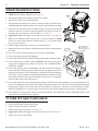
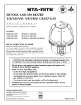
MASTERTEMP ® POOL AND SPA HEATER
INSTALLATION AND USER’S GUIDE
FOR YOUR SAFETY - READ BEFORE OPERATING
If you do not follow these instructions exactly, a fire or explosion may result, causing
property damage, personal injury or loss of life. For additional free copies of this
manual; call (800) 831-7133.
FOR YOUR SAFETY - This product must be installed and serviced by authorized personnel, qualified inpool/spa
heater installation. Improper installation and/or operation can create carbon monoxide gas and flue gases which can
cause serious injury, property damage, or death. For indoor installations, as an additional measure of safety, Pentair
Aquatic Systems strongly recommends installation of suitable Carbon Monoxide detectors in the vicinity of this
appliance and in any adjacent occupied spaces. Improper installation and/or operation will void the warranty.
120/240 VAC NATURAL GAS/LP GAS
Models
Natural
Propane
175K BTU/HR
200K BTU/HR (ASME)
200K BTU/HR
200K BTU/HR (HD ASME)
250K BTU/HR
250K BTU/HR (HD)
250K BTU/HR (ASME)
250K BTU/HR (HD ASME)
300K BTU/HR
400K BTU/HR
400K BTU/HR (HD)
400K BTU/HR (ASME)
400K BTU/HR (HD ASME)
460792
461000
460730
461032
460732
460806
460771
461020
460734
460736
460805
460775
461021
460793
461001
460731
–
460733
–
460772
–
460735
460737
–
460776
–
OWNER:
Retain For
Future
Reference
Improper installation, adjustment, alteration, service or maintenance can cause
propertydamage, personal injury or death. Installation and service must be performed
by a qualified installer, service agency or the gas supplier.
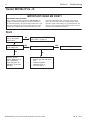
WHAT TO DO IF YOU SMELL GAS
FOR
YOUR
SAFETY
•
•
•
•
Do not try to light any appliance.
Do not touch any electrical switch; do not use any phone in your building.
Immediately call your gas supplier from a neighbor's phone.
Follow the gas supplier's instructions.
If you cannot reach your gas supplier, call the fire department.
DO NOT store or use gasoline or other flammable vapors and liquids in the vicinity
of this or other appliances.
Pentair Water Pool and Spa, Inc.
1620 Hawkins Ave., Sanford, NC 27330 • (800) 831-7133 or (919) 566-8000
10951 W. Los Angeles Ave., Moorpark, CA 93021 • (800) 831-7133 or (805) 553-5000
Rev. M 1-8-15
MASTERTEMP® Pool and Spa Heater Installation and User’s Guide
2
Customer Service and Tecnincal Support
If you have questions about ordering Pentair Quality Water Systems replacement parts, and
pool
products, please call:
Phone: (800) 831-7133
Fax: (800) 284-4151
(8 A.M. to 7:00 PM Eastern Time/Pacific Time)
Web sites: www.pentairpool.com - www.staritepool.com
P/N 472592 Rev. M 1/2015
MASTERTEMP® Pool and Spa Heater Installation and User’s Guide
Rev. M 1-8-15
3
Contents
Section 1. Heater Identification Information .......................................................................
Section 2. Warning and Safety Information .........................................................................
4
5
Important Notices .................................................................................................................................................................................
Warranty Information ............................................................................................................................................................................
Code Requirements ..............................................................................................................................................................................
Consumer Information and Safety Information ......................................................................................................................................
General Specifications .........................................................................................................................................................................
5
5
6
6-9
9
Section 3. Installation .............................................................................................................
10
Heater Description ................................................................................................................................................................................
Putting the Heater into Service ............................................................................................................................................................
Specifications ......................................................................................................................................................................................
Plumbing Connections ..........................................................................................................................................................................
Valves ..................................................................................................................................................................................................
Manual By-Pass ..................................................................................................................................................................................
Water Connections ...............................................................................................................................................................................
Below Pool Level Installation ................................................................................................................................................................
Gas Connections .................................................................................................................................................................................
Sediment Traps ....................................................................................................................................................................................
Gas Pipe Sizing ...................................................................................................................................................................................
Testing Gas Pressure/Gas Pressure Requirements .............................................................................................................................
Outdoor Installation (US and Canada) / Heater Clearances ..................................................................................................................
Outdoor Installation Venting Guidelines ................................................................................................................................................
Indoor Venting — General Requirements (Category I and Category III requirements) .........................................................................
Heater Clearances — General Requirements (Indoor Installation for US or Outdoor Shelter for Canada) .............................................
Outside Vent Cover Removal ...............................................................................................................................................................
Combustion Air Supply /Direct Air Intake Duct with 3-inch PVC Pipe (Indoor Installation) .....................................................................
Corrosive Vapors and Possible Causes ................................................................................................................................................
Vent Installation (Indoor Installation for U.S. or Outdoor Shelter for Canada) ........................................................................................
Vertical Venting - Negative Pressure ...................................................................................................................................................
Horizontal or Vertical Venting - Positive Pressure ................................................................................................................................
Connecting Special Gas Venting ..........................................................................................................................................................
Outdoor Shelter Vent Installation ..........................................................................................................................................................
Garage or Utility Room Installation .......................................................................................................................................................
Control Panel Indexing .........................................................................................................................................................................
Final Installation Check ........................................................................................................................................................................
Electrical Connections ..........................................................................................................................................................................
Fireman’s Switch Connection/Remote Control Connections ..................................................................................................................
MasterTemp Heater Wiring Diagram .....................................................................................................................................................
Electrical Schematic Ladder Diagram ...................................................................................................................................................
Section 4. Operation ...............................................................................................................
Basic System Operation ......................................................................................................................................................................
HSI (Hot-Surface Ignition) Lighting/Operation .......................................................................................................................................
Operating .............................................................................................................................................................................................
To Turn Off Gas to Appliance ...............................................................................................................................................................
Safety Controls ....................................................................................................................................................................................
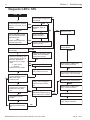
Section 5. Troubleshooting ...................................................................................................
Initial Troubleshooting and Troubleshooting Chart .................................................................................................................................
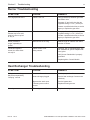
Heater Will Not Fire Troubleshooting ....................................................................................................................................................
LED Diagnostics ..................................................................................................................................................................................
Burner / Heat Exchanger Troubleshooting ............................................................................................................................................
Section 6. Maintenance ..........................................................................................................
Care and Maintenance ..........................................................................................................................................................................
Pressure Relief Valve ...........................................................................................................................................................................
After Start-Up ......................................................................................................................................................................................
Spring, Fall and Winter Operation .........................................................................................................................................................
Maintaining Pool Temperature ...............................................................................................................................................................
Energy Saving Tips ..............................................................................................................................................................................
Chemical Balance ................................................................................................................................................................................
Replacement Parts ..............................................................................................................................................................................
Rev. M 1-8-15
10
10
11
12
12
12
13
13
14
14
15
15-16
16
17
18
18
18
19-20
20
21
21 - 23
24
24 - 26
27
27
28
28
29
30
31
32
33
33
33
34
34
35 - 37
38
38
39 - 42
43 - 44
45
46
46
46
47
47
48
49
48 - 49
50 - 54
MASTERTEMP® Pool and Spa Heater Installation and User’s Guide
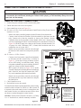
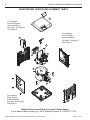
Section 1. Heater Identification Information
4
Section 1: Heater Identification Information
To identify the heater, see rating plate on the inner front panel of the heater. There are two designators for each
heater, one is the Model Number and the other is the Heater Identification Number (HIN).
a. Heater Identification Number (HIN)
The following example simplifies the identification system:
1) MT : MasterTemp
2) Model Size : (175, 200, 250, 300 or 400) : Input rating (Btu/hr) X 1000
3) Fuel Type : (LP = Propane gas or NA = Natural gas)
4) Construction : (STD = Standard Model)
(HD = Heavy Duty Model)
(ASME = ASME Certified Model)
(HD ASME = Heavy Duty ASME Model)
HEATER IDENTIFICATION INFORMATION — (HIN)
H. I. N.
HEATER IDENTIFICATION NUMBER
ID DESIGNATOR FOR PENTAIR AQUATIC SYSTEMS MASTERTEMP® HEATERS
Example:
1
2
3
4
MT
250
NA
ASME
CONSTRUCTION =
STD
= STANDARD MODEL
HD
= HEAVY DUTY MODEL
ASME = ASME CERTIFIED MODEL
HD ASME = HEAVY DUTY ASME MODEL
FUEL TYPE =
NA = NATURAL GAS
LP = PROPANE GAS
MODEL SIZE = BTU INPUT in 1000 of BTU / HR
MT = MASTERTEMP
MASTERTEMP® Pool and Spa Heater Installation and User’s Guide
Rev. M 1-8-15
Section 2.
Warning and Safety Instructions
5
Section 2: Warning and Safety Instructions
IMPORTANT SAFETY INSTRUCTIONS
READ AND FOLLOW ALL INSTRUCTIONS
SAVE THESE INSTRUCTIONS
MASTERTEMP ®
Pool and Spa Heater
Congratulations on your purchase of the MasterTemp Pool and Spa Heater. Proper installation and service of your new
heating system and correct chemical maintenance of the water will ensure years of enjoyment. The MasterTemp heater
is a compact, lightweight, efficient, induced-draft, gas fired high performance pool and spa heater that can be directly
connected to schedule 40 PVC pipe. The MasterTemp heater also comes equipped with the Pentair multifunction
temperature controller which shows, at a glance, the proper functioning of the heater. All MasterTemp heaters are
designed with a direct ignition device, HSI (hot-surface ignition), which eliminates the need for a standing pilot. The
MasterTemp heater requires an external power source (120/240 VAC 60 Hz) to operate.
SPECIAL INSTRUCTIONS TO OWNER: Retain this manual for future reference. This instruction manual provides
operating instructions, installation and service information for the MasterTemp high performance heater. The information
in this manual applies to all MasterTemp heater models. READ AND REVIEW THIS MANUAL COMPLETELY,
it is very important that the owner/installer read and understand the section covering installation instructions, and recognize
the local and state codes before installing the MasterTemp heater. Its use will reduce service calls and chance of injury
and will lengthen product life. History and experience has shown that most heater damage is caused by improper installation
practices.
IMPORTANT NOTICES
For the installer and operator of the MasterTemp heater: The manufacturer’s warranty may be void if, for any
reason, the heater is improperly installed and/or operated. Be sure to follow the instructions set forth in this manual. If you
need any more information, or if you have any questions regarding to this pool heater, please contact Pentair Aquatic
Systems at (800) 831-7133.
WARRANTY INFORMATION
The MasterTemp pool and spa heater is sold with a limited factory warranty. Specific details are described on the
warranty registration card which is included with the product. Return the warranty registration card after filling in
the serial number from the rating plate inside the heater.
Pentair Aquatic Systems high standards of excellence include a policy of continuous product improvement resulting
in your state-of-the-art heater. We reserve the right to make improvements which change the specifications of the
heater without incurring an obligation to update the current heater equipment.
These heaters are designed for the heating of chlorine, bromine or salt system swimming pools and spas or
in non-stationary installations, and should never be employed for use as space heating boilers or general
purpose water heaters. The manufacturer’s warranty may be void if, for any reason, the heater is improperly
installed and/or operated. Be sure to follow the instructions set forth in this manual.
CAUTION
OPERATING THIS HEATER CONTINUOUSLY AT WATER TEMPERATURE BELOW 68° F. WILL CAUSE HARMFUL
CONDENSATION AND WILL DAMAGE THE HEATER AND VOID THE WARRANTY. Do not use the heater to protect
pools or spas from freezing if the final maintenance temperature desired is below 68° F., as this will cause condensation
related problems.
Rev. M 1-8-15
MASTERTEMP® Pool and Spa Heater Installation and User’s Guide
Section 2.
6
Warning and Safety Instructions
CODE REQUIREMENTS
Installation must be in accordance with all local codes and/or the latest edition of the National Fuel Gas Code,
ANSI Z223.1 and the latest edition of the National Electrical Code, NFPA 70 (US).
Installation in Canada must be in accordance with the latest CAN/CGA-B149.1 or .2 and CSA C22.1 Canadian
Electric Code, part 1.
The heater, when installed, must be electrically grounded and bonded in accordance with local codes, or, in absence of
local codes, with the National Electrical Code, ANSI/NFPA70 (US) or in Canada in accordance with the Canadian
Electric Code, part 1.as applicable.
DANGER
CARBON MONOXIDE GAS IS DEADLY – Exhaust from this pool heater contains toxic levels of carbon monoxide, a dangerous,
poisonous gas you cannot see or smell.
CONSUMER INFORMATION AND SAFETY
WARNING
The U.S. Consumer Product Safety Commission warns that elevated water temperature can be hazardous.
See below for water temperature guidelines before setting temperature.
1.
Spa or hot tub water temperatures should never exceed 104° F (40° C). A temperature of 100° F (38° C) is considered safe for a
healthy adult. Special caution is suggested for young children.
2.
Drinking of alcoholic beverages before or during spa or hot tub use can cause drowsiness which could lead to unconsciousness
and subsequently result in drowning.
3.
Pregnant women beware! Soaking in water above 102° F (39° C) can cause fetal damage during the first three months of pregnancy
(resulting in the birth of a brain-damaged or deformed child). Pregnant women should stick to the 100° F (38° C) maximum rule.
4.
Before entering the spa or hot tub, the user should check the water temperature with an accurate thermometer. Spa or hot tub
thermostats may err in regulating water temperatures by as much as 4° F (2.2° C).
5.
Persons with a medical history of heart disease, circulatory problems, diabetes or blood pressure problems should obtain their
physician's advice before using spas or hot tubs.
6.
Persons taking medication which induce drowsiness, such as tranquilizers, antihistamines or anticoagulants should not use spas
or hot tubs.
WARNING
Should overheating occur or the gas supply fail to shut off, turn off the manual gas control valve to the heater.
Do not use this heater if any part has been under water. Immediately call a qualified service technician to
inspect the heater and to replace any part of control system and gas control which has been under water.
MASTERTEMP® Pool and Spa Heater Installation and User’s Guide
Rev. M 1-8-15
Section 2.
Warning and Safety Instructions
7
SAFETY INFORMATION
The MasterTemp® pool heaters are designed and manufactured to provide many years of safe and reliable service when
installed, operated and maintained according to the information in this manual. Throughout the manual, safety warnings and
cautions are identified by the “ “ symbol. Be sure to read and comply with all of the warnings and cautions.
DANGER — CARBON MONOXIDE GAS IS DEADLY
READ OWNERS MANUAL COMPLETELY BEFORE OPERATING
THIS PRODUCT MUST BE INSTALLED AND SERVICED BY A PROFESSIONAL SERVICE
TECHNICIAN, QUALIFIED IN POOL HEATER INSTALLATION. Some jurisdictions require that
installers be licensed. Check with your local building authority about contractor licensing requirements.
Improper installation and/or operation could create carbon monoxide gas and flue gases which could cause
serious injury or death. Improper installation and/or operation will void the warranty.
Exhaust from this pool heater contains toxic levels of carbon monoxide, a dangerous, poisonous gas
you cannot see or smell. Symptoms of carbon monoxide exposure or poisoning include dizziness,
headache, nausea, weakness, sleepiness, muscular twitching, vomiting and inability to think clearly.
IF YOU EXPERIENCE ANY OF THE ABOVE SYMPTOMS, IMMEDIATELY TURN OFF THE POOL
HEATER, LEAVE THE VICINITY OF THE POOL OR SPA AND GET INTO FRESH AIR IMMEDIATELY.
THE POOL HEATER MUST BE THOROUGHLY TESTED BY A GAS PROFESSIONAL BEFORE
RESUMING OPERATION.
EXCESSIVE CARBON MONOXIDE EXPOSURE CAN CAUSE BRAIN DAMAGE OR DEATH.
NEVER use this pool heater indoors without specified ventilation system (and properly installed vent pipe).
NEVER use this pool heater in the home or in partly enclosed areas (such as garages), unless
the specified ventilation system is used. If used outdoors, install far from open windows, doors,
vents and other openings.
Pentair strongly recommends that all vents, pipes and exhaust systems be initially and periodically
tested for proper operation. This testing can be accomplished by using a hand-held carbon monoxide
meter and/or by consulting with a gas professional.
Pool heaters must be used in conjunction with carbon monoxide detectors installed near the pool heater.
The carbon monoxide detectors must be periodically inspected for proper operation so as to insure
continued safety. Broken or malfunctioning carbon monoxide detectors must be replaced immediately.
WARNING — FOR YOUR SAFETY
This product must be installed and serviced by a professional service technician, qualified in pool
heater installation. Some jurisdictions require that installers be licensed. Check with your local
building authority about contractor licensing requirements. Improper installation and/or operation
could create carbon monoxide gas and flue gases which could cause serious injury or death. Improper
installation and/or operation will void the warranty.
WARNING — This heater is equipped with an unconventional gas control valve that is factory set with a
manifold pressure of -.2 inches wc. Improper installation, adjustment, alteration, service or
maintenance can cause property damage, personal injury or loss of life. Installation or service must
be performed by a qualified installer, service agency or the gas supplier. If this control is replaced, it
must be replaced with an identical control.
Do not attempt to adjust the gas flow by adjusting the regulator setting.
Rev. M 1-8-15
MASTERTEMP® Pool and Spa Heater Installation and User’s Guide
Section 2.
8
Warning and Safety Instructions
SAFETY INFORMATION, (cont’d.)
WARNING — Risk of fire or explosion from incorrect fuel use or faulty fuel conversion. Do not try to run a
heater set up for natural gas on propane gas or vice versa. Only qualified service technicians should
attempt to convert heater from one fuel to the other. Do not attempt to alter the rated input or type of
gas by changing the orifice. If it is necessary to convert to a different type of gas, consult your Pentair
dealer. Serious malfunction of the burner can occur which may result in loss of life. Any additions,
changes, or conversions required in order for the appliance to satisfactorily meet the application
needs must be made by a Pentair dealer or other qualified agency using factory specified and
approved parts. The heater is available for use with natural gas or LP (propane) gas only. It is not
designed to operate with any other fuels. Refer to the nameplate for the type of gas the heater is
equipped to use.
• Use heater only with the fuel for which it is designed.
• If a fuel conversion is necessary, refer this work to a qualified service technician or gas supplier
before putting the heater into operation.
WARNING — Risk of fire or explosion from flammable vapors. Do not store gasoline, cleaning fluids, varnishes,
paints, or other volatile flammable liquids near heater or in the same room with heater.
WARNING — Risk of explosion if unit is installed near propane gas storage. Propane (LP) gas is heavier
than air. Consult local codes and fire protection authorities about specific installation requirements
and restrictions. Locate the heater away from propane gas storage and filling equipment as specified
by the Standard for the Storage and Handling of Liquefied Petroleum Gases, CAN/CSA B149.2
(latest edition) or ANSI/NFPA 58 (latest edition).
WARNING — Risk of fire, carbon monoxide poisoning, or asphyxiation if exhaust venting system leaks.
Only qualified service technicians should attempt to service the heater, as leakage of exhaust
products or flammable gas may result from incorrect servicing.
WARNING — Risk of asphyxiation if exhaust is not correctly vented. Follow venting instructions exactly
when installing heater. Do not use a drafthood with this heater, as the exhaust is under
pressure from the burner blower and a draft hood will allow exhaust fumes to blow into the room
housing the heater. The heater is supplied with an integral venting system for outdoor installation.
A vent conversion kit (See Page 24 for Part Numbers for Conversion Kits) is available for installations
in enclosures (Canada) or indoors (U.S.). Use the specified venting, and only the specified venting,
when heater is installed in an enclosure or indoors. In Canada, this pool heater can only be installed
outdoors or in an enclosure that is not normally occupied and has no openings directly into occupied
areas. See Page 19 for enclosure venting requirements.
CAUTION — Label all wires prior to disconnection when servicing controls. Wiring errors can cause
improper and dangerous operation. Wiring errors can also destroy the control board.
• Connect heater to 120 or 240 Volt, 60 Hz., Single Phase power only.
• Verify proper operation after servicing.
• Do not allow children to play on or around heater or associated equipment.
• Never allow children to use the pool or spa without adult supervision.
• Read and follow other safety information contained in this manual prior to operating this pool
heater.
MASTERTEMP® Pool and Spa Heater Installation and User’s Guide
Rev. M 1-8-15
Section 2.
Warning and Safety Instructions
9
CONSUMER INFORMATION AND SAFETY
WARNING
The U.S. Consumer Product Safety Commission warns that carbon monoxide is an "invisible killer". Carbon monoxide
is a colorless and odorless gas.
1. Carbon monoxide is produced by burning fuel, including natural gas and propane.
2. Proper installation, operation and maintenance of fuel-burning appliances in the home is the most important
factor in reducing carbon monoxide poisoning.
3. Be sure that fuel burning appliances such as heaters are installed by professionals according to manufacturer's
instructions and codes.
4. Always follow the manufacturer's directions for safe operation.
5. Have the heating system (including vents) inspected and serviced annually by a trained service technician.
6. Examine vents regularly for improper connections, visible cracks, rust or stains.
7. Install battery-operated carbon monoxide alarms. The alarms should be certified to the requirements of the
most recent UL, IAS, CSA and IAPMO standard for carbon monoxide alarms. Test carbon monoxide alarms
regularly and replace dead batteries.
GENERAL SPECIFICATIONS
NOTICE:
•
Combustion air contaminated by corrosive chemical fumes can damage the heater and will void the warranty.
•
The Combination Gas Control Valve on this heater differs from most appliance gas controls. If it must be replaced,
for safety reasons replace it only with an identical gas control.
•
The access door panels must be in place to provide proper ventilation. Do not operate the heater for more than five (5)
minutes with the access door panels removed.
•
This heater is design certified by CSA International as complying with the Standard for Gas Fired Pool Heaters,
ANSI Z21.56/CSA 4.7, and is intended for use in heating fresh water swimming pools or spas.
•
The heater is designed for the heating of chlorine, bromine or salt system swimming pools and spas. It should NOT be
used as a space heating boiler, or general purpose water heater.
•
The heater is design certified by CSA International for installation on combustible flooring. Specified minimum
clearances must be maintained to combustible surfaces (see “Heater Clearances”, page 18).
•
The heater should be located in an area where leakage of the heater or connections will not result in damage to the
area adjacent to the heater or to the structure. When such locations cannot be avoided, it is recommended that a
suitable drain pan, adequately drained, be installed under the heater. The pan must not restrict air flow.
•
The heater may not be installed within 5 ft. (1.5M ) of the inside surface of a pool or spa unless it is separated by a solid
fence, wall or other permanent barrier.
Rev. M 1-8-15
MASTERTEMP® Pool and Spa Heater Installation and User’s Guide
Section 3.
10
Installation Instructions
Section 3: Installation Instructions
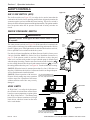
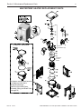
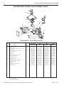
HEATER DESCRIPTION
Two inch PVC water piping connects directly to the manifold/header
on the heat exchanger using 2" PVC slip unions provided with the
heater. The outer manifold remains cool; no heat sinks are required.
A thermal regulator and an internal bypass regulate the water flow
through the heat exchanger to maintain the correct outlet
temperature. The heater operator control panel board assembly is
located on top of the heater.
SEQUENCE OF OPERATION
Exhaust
Gas
Figure 1 is a diagram of the heater showing how it operates. Precisely
matched orifice plates meter the air and gas into the mixer. The
blower draws the air and gas through the mixer and forces it into
the burner’s flame holder. A sealed heat exchanger surrounds the
flame holder, discharging exhaust gases out the flue.
Air
Blower
Mixer
Inlet
(Cold
Water)
Outlet
(Mixed
Water)
Burner
Heating Coils
An electronic temperature sensing thermistor in the manifold
adapter inlet controls the heater operation. When the inlet water
Figure 1.
temperature drops below the temperature set on the operating
control, the burner controller supplies power to the combustion
air blower through a series of safety interlocks. The interlocks consist of:
• the pressure switch (PS), which senses that the pump is running,
• the high limit switch (HLS), which opens if the heat exchanger outlet temperature goes above 135° F (57° C), and
• the air flow switch (AFS), which senses the pressure drop across the air metering orifice,
• the automatic gas shut-off (AGS) switch, which opens if the heat exchanger outlet temperature goes above 140° F
(60° C).
• the stack flue sensor (SFS), which shuts down the heater if the flue gas temperature reaches 480° F (249° C).
The air flow switch (AFS) senses the pressure drop across the air metering orifice. As soon as there is sufficient air flow,
the AFS closes, closing the circuit to the hot surface igniter (HSI), which ignites the fuel mixture. On a call for heat, the
blower and HSI are energized. In about 20 seconds, the gas valve opens and ignition occurs. The HSI then switches to a
sensing mode and monitors the flame.
The heater is equipped with a digital operating control that enables the user to pre-set the desired pool and spa water
temperatures. The control enables the user to select between pool and spa heating, and features a digital display that
indicates the water temperature.
PUTTING THE HEATER INTO SERVICE
If the heater is installed below the level of the pool, or more than two feet above pool level, the pressure switch setting
should be adjusted. See WATER PRESSURE SWITCH, in the SAFETY CONTROLS Section.
Before putting the heater into service for the first time, follow the instructions under “BEFORE START-UP” (page 33) in
the front of this manual. Check for proper operation of the heater by following the steps under “OPERATION
INSTRUCTIONS.”
Damage to equipment caused by improper installation or repair will void the warranty.
MASTERTEMP® Pool and Spa Heater Installation and User’s Guide
Rev. M 1-8-15
Section 3. Installation Instructions
11
SPECIFICATIONS
These installation instructions are designed for use by qualified personnel only, trained especially for installation of this
type of heating equipment and related components. Some states require installation and repair by licensed personnel. If
this applies in your state, be sure your contractor bears the appropriate license. See Figure 2 for Outdoor and Indoor
Installations.
DIMENSIONS IN INCHES
23.02"
(58.5 cm)
28.15"
(71.5 cm)
21.0"
(53.3 cm)
32.61"
(82.8 cm)
16"
(40.6 cm)
FRONT
TOP
ELECTRICAL
CONDUIT PORT
28.2"
(71.6 cm)
22.7"
(57.7 cm)
16.0"
(40.6 cm)
10.13"
(25.7 cm)
5.6"
(14.2 cm)
EXHAUST SIDE
PLUMBING SIDE
Figure 2.
Rev. M 1-8-15
MASTERTEMP® Pool and Spa Heater Installation and User’s Guide
Section 3. Installation Instructions
12
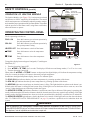
PLUMBING CONNECTIONS
The MasterTemp heater has the unique capability of direct
schedule 40 PVC plumbing connections. A set of bulkhead
fittings is included with the MasterTemp heater to insure
conformity with Pentair’s recommended PVC plumbing
procedure. Other plumbing connections can be used. See
Figure 3 for plumbing connections.
CAUTION
Before operating the heater on a new installation, turn
on the circulation pump and bleed all the air from the
filter using the air relief valve on top of the filter. Water
should flow freely through the heater. Do not operate
the heater unless water in the pool/spa is at the proper
level. If a manual by-pass is installed, temporarily close it
to insure that all air is purged from the heater.
TO
POOL
POOL
HEATER
PUMP
FILTER
MANUAL
BY-PASS
GATE
VALVE
Figure 3.
FROM
POOL
WATER CONNECTIONS
The heater requires proper water flow and pressure for its
operation. See Figure 5 for the recommended installation.
The filter pump discharges to the filter, the filter discharges
to the heater, and the heater discharges directly to the pool
or spa.
A manual bypass valve should be installed across the heater
when the pump flow exceeds 120 GPM (454 LPM). See
“WATER FLOW RATE” on page 13- Table 1 for setting of
the manual by-pass valve.
3-Way
Valve
Chlorinator
Check Valve
Heater
Main
Drain
Filter
Make sure that the outlet plumbing from the heater contains
no shut-off valves or other flow restrictions that could prevent
flow through the heater (except for pool installations as noted
below, or winterizing valves where needed). To switch flow
between the pool and spa, use a diverter valve. Do not use
any valve that can shut off the flow.
Pool
Install the chemical feeder downstream of the heater. Install
a chemical resistant one-way check valve between the heater
and the chemical feeder to prevent back-siphoning through
the heater when the pump is off.
From Pool
Spa
Pump
3-Way
Valve
3-Way
Valve
Figure 5.
NOTICE: If the heater is plumbed in backwards, it will cycle continuously. Make sure piping from filter is not reversed
when installing heater.
Connect the heater directly to 2" PVC pipe, using the integral unions provided. Heat sinks are not required. The low
thermal mass of the heater will prevent overheating of the piping connected to the pump even if the heater shuts down
unexpectedly.
Occasionally a two-speed pump will not develop enough pressure on the low speed to operate the heater. In this case, run
the pump at high speed only to operate the heater. If this does not solve the problem, do not try to run the heater. Instead,
correct the installation.
Do not operate the heater while an automatic pool cleaner is also operating. If the circulation pump suction is plugged (for
example by leaves), there may not be adequate flow to the heater. Do not rely on the pressure switch in this case.
MASTERTEMP® Pool and Spa Heater Installation and User’s Guide
Rev. M 1-8-15
Section 3. Installation Instructions
13
VALVES
When any equipment is located below the surface of the pool or spa, valves should be placed in the circulation piping
system to isolate the equipment from the pool or spa. Check valves are recommended to prevent back-siphoning. Backsiphoning is most likely to occur when the pump stops, creating a pressure-suction differential. Do NOT sanitize the pool
by putting chlorine tablets or sticks into the skimmer(s). When the pump is off, this will cause a high concentration of
chlorine to enter the heater, which could cause corrosion damage to the heat exchanger.
CAUTION
Exercise care when installing chemical feeders so as to not allow back siphoning of chemical into the heater, filters
or pump. When chemical feeders are installed in the circulation of the piping system, make sure the feeder outlet line
is down stream of the heater, and is equipped with a positive seal noncorrosive “Check Valve”, (P/N R172288),
between the feeder and heater.
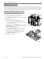
MANUAL BY-PASS
Figure 4.
Where the water flow rate exceeds the maximum 120 GPM, a manual
bypass should be installed and adjusted. After installing the valve, adjust
the valve to bring the flow rate within the acceptable range. Then remove
the valve handle or lock it in place to avoid tampering. See Figure 4.
Model
Min. (GPM) (LPM)
Max. (GPM) (LPM) *
175
20 (76)
120 (454)
200
20 (76)
120 (454)
250
25 (95)
120 (454)
300
30 (114)
120 (454)
400
40 (152)
120 (454)
Table 1.
Cool water
* Do not exceed the maximum recommended flow
rate for the connecting piping.
Warm water out
1. Set Manual By-Pass Valve.
2. Remove Handle.
* Pumps 2 HP or larger can produce water pressure
flow in excess of 120 GPM. For these pumps, a
BY-PASS VALVE is recommended.
Outlet to pool
See page 46 for Pressure Relief Valve Installations.
Inlet to heater
BELOW POOL LEVEL INSTALLATION
If the heater is below water level, the pressure switch must be adjusted. This adjustment must be done by a qualified
service technician. See following CAUTION before installation.
CAUTION
BELOW OR ABOVE POOL INSTALLATION
The water pressure switch is set in the factory at 3.00 PSI (± 0.75 PSI). This setting is for a heater installed at pool level.
If the heater is to be installed more than 1’ above or below, the water pressure switch must be adjusted by a qualified
service technician. See page 35, Figure 29.
FLOW SWITCH
If the heater is installed more than 5’ above the pool or more than 4’ below the pool level, you will be beyond the limits
of the pressure switch and a flow switch must be installed. Locate and install the flow switch externally on the outlet
piping from the heater, as close as possible to the heater. Connect the flow switch wires in place of the water
pressure switch wires.
Rev. M 1-8-15
MASTERTEMP® Pool and Spa Heater Installation and User’s Guide
Section 3. Installation Instructions
14
GAS CONNECTIONS
GAS LINE INSTALLATIONS
Before installing the gas line, be sure to check which gas the heater has been designed to burn. This is important because
different types of gas require different gas pipe sizes. The rating plate on the heater will indicate which gas the heater is
designed to burn. The Table 2, shown on page 15, show which size pipe is required for the distance from the gas meter to
the heater. The table is for natural gas at a specific gravity of .65 and propane at a specific gravity of 1.55.
When sizing gas lines, calculate three (3) additional feet of straight pipe for every elbow used. When installing the gas line,
avoid getting dirt, grease or other foreign material in the pipe as this may cause damage to the gas valve, which may result
in heater failure.
The gas meter should be checked to make sure that it will supply enough gas to the heater and any other appliances
that may be used on the same meter. The gas line from the meter will usually be of a larger size than the gas valve
supplied with the heater. Therefore a reduction of the connecting gas pipe will be necessary. Make this reduction
as close to the heater as possible.
The heater requires a gas supply of not less than 4" (10.2 cm) wc and not more than 14" (35.6 cm) wc. Gas supply
pressures outside of this range may result in improper burner operation. A minimum flowing or dynamic inlet pressure
(while the heater is running) of 4" (10.2cm) wc is required to maintain input rating with no more than a 2” pressure drop
between static and dynamic. The gas supply must be installed in accordance with the National Fuel Gas Code,
ANSIZ223.1, or standard CSA B149.1, Natural Gas and Propane Installation Codes, as applicable and all applicable
local codes. Install a manual shut-off valve and a sediment trap and union located outside the heater panels, see Figure 6.
Do not use a restrictive gas cock. The following minimum gas pipe sizes are recommended for natural gas supply piping,
see Table 2 on page 15. For low pressure LP gas, pipe size may be reduced by 1/4", with a minimum pipe size of 1/2".
Check for compliance with local codes.
The heater and any other gas appliances must be disconnected from the gas supply piping system during any pressure
testing on that system, (greater than ½ PSI). The heater and its gas connection must be leak tested before placing the
heater in operation. Do not use flame to test the gas line. Use soapy water or another nonflammable method.
NOTE
A manual main shut-off valve must be installed externally to the heater.
WARNING
DO NOT INSTALL THE GAS LINE UNION INSIDE THE HEATER CABINET. THIS WILL VOID YOUR WARRANTY.
SEDIMENT TRAPS
Install a sediment trap and union located outside the
heater panels in accordance with National code
requirements. Do not use a restrictive gas cock. The
sediment trap shall be either a tee fitting with a capped
nipple in the bottom outlet which can be removed for
cleaning, as illustrated in Figure 6, or an other device
recognized as an effective sediment trap. All gas piping
should be tested after installation in accordance with
local codes.
18–24" of 3/4"
Manual
Gas line from
Shut-off
Valve
Valve
1" Dia. or larger
(See "Recommended
Pipe Sizes" Chart)
Bell
Reducer
At least 9"
Union
At least 3"
Sediment
Trap
Figure 6.
MASTERTEMP® Pool and Spa Heater Installation and User’s Guide
Rev. M 1-8-15
Section 3. Installation
15
GAS PIPE SIZING
STAGE TWO “LOW PRESSURE” GAS PIPE SIZING
PIPE SIZING FOR GAS LINE CONNECTIONS
MAXIMUM EQUIVALENT PIPE LENGTH (Ft.)
Natural Gas at 1000 B.T.U. per Cubic Foot
Propane Gas at 2500 B.T.U. per Cubic Foot
1/2”
MODEL
Table 2.
3/4”
1”
1-1/4”
1-1/2”
2”
2-1/2”
NAT PRO NAT PRO NAT PRO NAT PRO NAT PRO NAT PRO NAT PRO
175
-
20’
30’
80’
125’ 250’ 450’ 600’
-
-
-
-
-
-
200
-
20’
30’
80’
125’ 250’ 450’ 600’
-
-
-
-
-
-
250
-
10’
20’
50’
70’
150’ 250’ 500’ 600’
-
-
-
-
-
300
-
-
10’
30’
50’
100’ 200’ 350’ 400’ 600’
-
-
-
-
400
-
-
-
10’
20’
60’
-
-
-
100’ 150’ 200’ 450’ 400’
TESTING GAS PRESSURE
Before operating the heater, the heater and its gas connections must be leak tested. Do NOT use an open flame to test
for leaks. Test all gas connections for leaks with soapy water or another non-flammable method (see page 14).
The heater and its individual shut-off valve must be disconnected from the gas supply piping system during any pressure
testing of that system at test pressures in excess of 1/2 psig (3.5 kPa).
The heater must be isolated from the gas supply system by closing its individual manual shut-off valve during any pressure
testing of the gas supply at test pressures equal to or less than 1/2 psig (3.5 kPa).
CHECKING THE GAS PRESSURE THROUGH THE COMBINATION GAS CONTROL VALVE
WARNING
Risk of fire and explosion. Improper installation, incorrect adjustment, alteration, service, or maintenance of the Combination
Gas Control Valve can lead to fire or explosion, causing loss of life, personal injury, and/or property damage. If it is necessary
to adjust the gas valve, this must be done by only by a qualified service agency. These instructions are for the use of
qualified service technicians only!
This appliance is equipped
with an unconventional gas
control valve that is factory
set with a manifold
pressure of –.2" (–0.5cm)
wc. Installation or service
must be performed by a
qualified installer, service
agency, or the gas supplier.
If this control valve is
replaced, it must be
replaced with an identical
control.
Connection
To Air Flow
Switch
for Service
To Gas
Valve Vent
To Air Flow
Switch
Connection
for Test
To High Side
of Differential
Pressure Gauge
To Gas
Valve Vent
Figure 7.
Pressure Tap
Inlet
Vent
Pressure Tap
To Low Side of
Differential Pressure Gauge
The combination gas
valve incorporates dual shut-off valves and a negative-pressure regulator. For proper operation, the regulated pressure
at the outlet manifold of the valve must be –0.2" (–0.5cm) wc below the reference pressure at the blower mixer inlet,
and the gas valve ‘VENT’ tap must be connected to the end cap air orifice as shown in Figure 7.
Do not attempt to adjust the gas input by adjusting the regulator setting. The correct gas regulator setting is
required to maintain proper combustion and must NOT be altered.
Rev. M 1-8-15
MASTERTEMP® Pool and Spa Heater Installation and User’s Guide
Section 3. Installation Instructions
16
CAUTION
The use of Flexible Connectors (FLEX) is NOT recommended unless they are properly sized according to the
supplier recommendations for the heater rating.
GAS PRESSURE REQUIREMENTS
Natural
Gas Pressure
Propane
Model
Inches W.C.
Maximum Inlet
MT
14
14
Minimum Inlet
MT
4
4
Manifold
MT
-0.2 ± 0.1
-0.2 ± 0.1
NOTE: All readings must be taken while heater is operating.
Any adjustments or readings made while heater is off will
result in performance problems.
OUTDOOR INSTALLATION
Table 3.
(U.S. and Canada)
For heaters located outdoors, using the built-in stackless venting system.
WARNING
Risk of explosion if a unit burning propane gas is installed in a pit or other low spot. Propane is heavier than air. Do not
install the heater using propane in pits or other locations where gas might collect. Consult your local building code officials to
determine installation requirements and specific installation restrictions of the heater relative to propane storage tanks and
filling equipment. Installation must meet the requirements for the Standard for the Storage and Handling of Liquid Petroleum
Gases, ANSI/NFPA 58 (latest edition) in the U.S., or CAN/CSA B149.2 (latest edition) in Canada. Consult local codes and fire
protection authorities about specific installation restrictions.
Locate the heater on a level surface in an open area that is protected from drainage or run-off. Install the heater in an area
where leaves or other debris will not collect on or around the heater.
To avoid damage to the electronic components in the heater, take care to prevent prolonged exposure to driving sources
of water (such as lawn sprinklers, heavy roof runoff, hoses, etc.). Avoid operation in persistent, extreme, moist or salty
environments. In extreme weather, shut down the heater and disconnect the power to it until the weather has moderated.
In areas subject to hurricanes or very high winds, purchase the Bolt Down Bracket Kit, P/N 460738.
HEATER CLEARANCES – OUTDOOR
IMPORTANT!
• In an outdoor installation it is important to ensure water is diverted from overhanging eves with a proper
gutter/drainage system. The heater must be set on a level foundation for proper drainage.
• This unit shall not be operated outdoors at temperatures below -20o F.
If the heater is located under a roof overhang, there must be at least three (3) feet (1m) of
clearance between the bottom of the overhang and the top of the heater exhaust vent, see Figure
8. If the heater is under a roof overhang, the space around the heater must be open on three
sides. DO NOT, under any circumstances, install the heater under ANY deck.
For Heater mounting
bolts and clamps,
purchase separately
Bolt Down Bracket Kit,
Part No. 460738.
Lead
Anchor
MASTERTEMP® Pool and Spa Heater Installation and User’s Guide
Rev. M 1-8-15
Section 3. Installation Instructions
17
For minimum exhaust vent clearances for all building openings, including but not limited to vented eaves, doors, windows,
gravity air inlet, see Figure 9, show below.
In Canada, the heater must be installed with the top of the vent at least 10 feet (3m) below, or to either side of, any opening
into a building.
Orient the heater for convenient access to the water connections and the gas and electrical connections.
Note: Check local building codes for installing the heater from any property line set back requirements (see the
installation diagram below).
CAUTION
If installing the heater next to or near an air
conditioning unit or a heat pump, allow a
minimum of 36 in. (91.4 cm) between the air
conditioning unit and the heater.
3 ft. (1 M) or more
Figure 8.
OUTDOOR INSTALLATION
VENTING GUIDELINES
From window or door
4'
3'
SIDE VIEW
4'
Property Line
6 in
4'
From building wall
Force
Air Inlet
s
de
co ts.
g
n
n
i
ild me
bu uire
al
oc k req
l
k
ec bac
Ch set
r
fo
Exhaust Grill
(Vent)
Building
Vent Termination:
Must be at least 3 ft. above any forced
air inlet located within a 10 ft. radius.
Must be located 6 in. away from the building
wall and the following distances away from any building
wall openings, included but not limited to vented eaves,
doors, windows, gravity air inlet:
4 ft. below,
4 ft. horizontally
Figure 9.
Rev. M 1-8-15
MASTERTEMP® Pool and Spa Heater Installation and User’s Guide
Section 3. Installation Instructions
18
INDOOR VENTING — General Requirements
The heater may be installed as a Category I or Category III appliance.
Vented Appliance (Category I) – Vertical only
An appliance that operates with a nonpositive vent static pressure and with a vent gas temperature that avoids excessive
condensate production in the vent, see pages 20-23.
Vented Appliance (Category III) – Vertical or Horizontal
An appliance that operates with a positive vent static pressure and with a vent gas temperature that avoids excessive
condensate production in the vent, see pages 24-26.
If you are considering connecting this heater to a pre-existing vent system, make sure that the vent system meets the
appropriate venting requirements as given in this manual on pages 18-28. If not, replace the vent system. DO NOT use
a draft hood with this heater.
The MasterTemp heaters are capable of a 270-degree discharge rotation and operate with a positive vent static pressure
and with a vent gas temperature less than 400° F (204° C). The total length of the horizontal run must not exceed the length
that is listed in Table 11 on page 21-22.
HEATER CLEARANCES — General Requirements
INDOOR INSTALLATION (U.S.) OR OUTDOOR SHELTER (CANADA)
The following clearances must be maintained from combustible surfaces:
TOP .............................. 6 in. (15 cm)
EXHAUST SIDE .......... 6 in. (15 cm)
HEADER SIDE ............ 6 in. (15 cm)
For service access, it is advisable to allow for
sufficient clearance on at least one door panel.
6 in.
DOOR PANELS† ........ 6 in. (15 cm)
Note (†) For service access it is advisable to allow for sufficient clearance
on at least one door panel. The heater is design certified by CSA
International for installation on combustible flooring. For installation on
carpeting, the heater must be mounted on a metal or wood panel that
extends at least three inches (10cm) beyond the base of the heater. If the
heater is installed in a closet or alcove, the entire floor shall be covered by
the panel. On an outdoor shelter installation, the exhaust discharges into a
vent pipe. Orient the heater so that the vent pipe does not interfere with
adjustment of the operating controls. The control panel located on the top
panel can be rotated to any of the three sides of the heater for easy
access. However, the control panel must not be located on the side where
the vent is located.
OUTSIDE VENT COVER REMOVAL
6 in.*
6 in.*
6 in.
Figure 10.
The heater is supplied from the factory with a built-in stackless outside vent for outdoor installation. Remove the outside
vent cover for outdoor shelter installation.
MASTERTEMP® Pool and Spa Heater Installation and User’s Guide
Rev. M 1-8-15
Section 3. Installation Instructions
19
COMBUSTION AIR SUPPLY
For indoor installation, the heater location must provide sufficient air supply for proper combustion and ventilation of the
surrounding area.
The minimum requirements for the air supply specify that the room in which a heater is installed should be provided with
two permanent air supply openings; one within 12 inches (30cm) of the ceiling, the other within 12 inches (30cm) of the
floor for combustion air, in accordance with the latest edition of ANSI Z223.1, or the National Fuel Gas code, the CSA
B149.1, Natural Gas and Propane Installation Codes, as applicable, and any local codes that may apply. These openings
shall directly, or through duct, connect to outdoor air.
Note: For indoor installations where combustion air might be insufficient, see “Direct Air Intake Duct
with 3-inch PVC Pipe (Indoor Installation)” below.
Air Supply Requirements Guide
for MasterTemp Heaters
Minimum Net Free Open Area for Each Opening*
(Square Inches/Centimeters)
All Air From Inside Building
All Air From Outside Building
Model
Combustion
Vent
Combustion
Vent
175
200 sq. in.
1290 sq. cm.
200 sq. in.
1290 sq. cm.
50 sq. in.
323 sq. cm.
50 sq. in.
323 sq. cm.
200
200 sq. in.
1290 sq. cm.
200 sq. in.
1290 sq. cm.
50 sq. in.
323 sq. cm.
50 sq. in.
323 sq. cm.
250
250 sq. in.
1613 sq. cm.
250 sq. in.
1613 sq. cm.
63 sq. in.
406 sq. cm.
63 sq. in.
406 sq. cm.
300
300 sq. in.
1935 sq. cm.
300 sq. in.
1935 sq. cm.
75 sq. in.
484 sq. cm.
75 sq. in.
484 sq. cm.
400
400 sq. in.
2580 sq. cm.
400 sq. in.
2580 sq. cm.
100 sq. in.
645 sq. cm.
100 sq. in.
645 sq. cm.
* Area indicated is for one of two openings; one at floor level and one at the ceiling.
Table 4.
Direct Air Intake Duct with 3-inch PVC Pipe (Indoor Installation)
For indoor heater installations where combustion air supply might be insufficient, the MasterTemp® Heater is certified for
a direct air intake duct using 3-inch PVC pipe. If outside air is drawn through 3” PVC duct directly into the heater, PVC
pipe can be installed in accordance with the following requirements:
The air intake opening MUST be installed at least 1 ft. above the roof line or normal snow levels for free air flow. The
Category I or III exhaust vent termination cap must have at least 3 ft. minimum vertical clearance from air intake duct.
(See diagram on page 20).
Rev. M 1-8-15
MASTERTEMP® Pool and Spa Heater Installation and User’s Guide
Section 3. Installation Instructions
20
Combustion 3 in. PVC Pipe
Inlet Air Intake Duct Requirements*
Combustion Air Intake 3 in. Pipe
(Vertical or Horizontal)
No. of 90° Elbows Maximum Length in Feet (M)
0
70 ft. (21.3 M)
1
58 ft. (17.7 M)
2
46 ft. (14.0 M)
3
34 ft. (10.4 M)
4
22 ft. ( 6.7 M)
Table 5.
WARNING!
DO NOT USE PVC PIPE FOR FLUE
EXHAUST VENT. FLUE EXHAUST
VENT TEMPERATURES CAN BE IN
EXCESS OF 400° F. FLUE EXHAUST
VENT MUST BE CATEGORY I or
CATEGORY III METAL VENT.
Note (*): Combustion Air Intake Duct Connection Kit (Part Number 461031) for all MasterTemp heater models can be
purchased separately. See page 52 for parts list.
NOTE
Each 90-degree elbow reduces the maximum horizontal PVC air intake duct run by 12 feet and each 45degree elbow in the PVC air intake duct run reduces the maximum run by 6 feet. See the Table 5 above for
the maximum lengths using 90-degree elbows.
Corrosive Vapors and Possible Causes
Area
CAUTION
Likely Contaminants
Chlorinated swimming
pools and spas
Pool or spa cleaning chemicals. Acids,
such as hydrochloric or muriatic acid.
New construction and
remodeling areas
Glues and cements, construction
adhesives, paints, varnishes, and paint
and varnish strippers. Waxes and
cleaners containing calcium or sodium
chloride.
Beauty parlors
Permanent wave solutions, bleaches,
aerosol cans containing chlorocarbons
or fluorocarbons.
Refrigeration plants or
various industrial finishing
and processing plants
Refrigerants, acids, glues and cements,
construction adhesives.
Dry cleaning and laundry
areas
Bleaches, detergents, or laundry soaps
containing chlorine. Waxes and cleaners
containing chlorine, calcium or sodium
chloride.
Chemicals should not be stored near the
heater installation. Combustion air can
be contaminated by corrosive chemical
fumes which can void the warranty.
Table 6.
MASTERTEMP® Pool and Spa Heater Installation and User’s Guide
Rev. M 1-8-15
Section 3. Installation Instructions
VENT INSTALLATION –
21
INDOOR INSTALLATION (U.S.) OR OUTDOOR SHELTER (CANADA)
(Category I)
Always vent the heater to the outdoors, see Note*.
• Vent it vertically using Type “B” double wall vent connector pipe.
NOTE *: Vent must be at least eight (8) feet away from
nearest vertical surface. Vents extending five (5) feet or
more above the roof must be braced or guyed.
Consult your local code officials for detailed information.
Locate the heater so as to minimize the length of horizontal venting and the number of vent elbows required. Horizontal
vent runs must slope up 1/4" per foot (2cm/M) from the heater to allow exhaust condensate to drain and it is recommended
to have a condensate drain as described in the venting installation instructions.
VERTICAL VENTING - NEGATIVE PRESSURE
(See Figures 11, 12 and 13)
Vent the heater vertically in a negative pressure (positive draft) system in
accordance with the National Fuel Gas Code, ANSI Z223.1/NFPA 54 and/or
CSA B149.1, Natural Gas and Propane Installation Codes, and local codes. Type
“B” Double-wall vent connector is recommended; however single-wall pipe is
allowed by the National Fuel Gas Code in some circumstances. Consult your
local code official for detailed information. Do not use a draft hood with this heater.
Clean the Interior Surface
Vent Body
V
4" x 8" Metal
Flue Collar
Vent Pipe
To connect a negative pressure metal gas vent to the heater, order the appropriate
Metal Flue Collar from the chart below:
Metal Flue Collar
Part No.
4 x 6"
77707-0076
4 x 8"
77707-0077
Combustion
Chamber
Flue Collar
Clean and RTV
This Surface
Figure 11.
1. See Table 7, to determine allowable vent sizes for your heater.
NOTICE: Table 7 is for installations in which the total lateral vent length (that is, the horizontal distance from the flue
collar to the main vertical portion of the vent) is less than 1/2 the total vent height (the vertical distance from the flue collar
to the vent termination) and which have three or less elbows in the system. For venting systems which do not meet these
conditions, consult the National Fuel Gas Code, ANSI Z223.1 (U.S.), or the standards CSA B149.1 and B149.2 (Canada).
Read “VERTICAL VENTING – NEGATIVE PRESSURE” before using this table.
Table 7. – Permitted Minimum and Maximum Vent Heights By Size and Heater Model
Type "B" Double-Wall Vent with Type "B" Double-Wall Connector in Feet (Meters)
Vent Size
Model 175
Height min./max.
Model 200
Height min./max.
Model 250
Height min./max.
Model 300
Height min./max.
Model 400
Height min./max.
6 in.
6 ft. (1.8)/100 ft. (30.5)
6 ft. (1.8)/100 ft. (30.5)
18 ft. (5.5)/100 ft. (30.5)
30 ft. (9)/100 ft. (30.5)
Not Rec.
7 in.
6 ft. (1.8)/100 ft. (30.5)
6 ft. (1.8)/100 ft. (30.5)
8 ft. (2.4)/100 ft. (30.5)
10 ft. (3)/100 ft. (30.5)
15 ft. (4.6)/100 ft. (30.5)
8 in.
6 ft. (1.8)/100 ft. (30.5)
6 ft. (1.8)/100 ft. (30.5)
6 ft. (1.8)/100 ft. (30.5)
6 ft. (1.8)/100 ft. (30.5)
8 ft. (2.4)/100 ft. (30.5)
9 and 10 in.
6 ft. (1.8)/50 ft. (15.3)
6 ft. (1.8)/50 ft. (15.3)
6 ft. (1.8)/50 ft. (15.3)
6 ft. (1.8)/100 ft. (30.5)
6 ft. (1.8)/100 ft. (30.5)
Type "B" Double-Wall Vent with Single-Wall Connector in Feet (Meters)
Vent Size
Model 175
Height min./max.
Model 200
Height min./max.
Model 250
Height min./max.
Model 300
Height min./max.
Model 400
Height min./max.
6 in.
6 ft. (1.8)/15 ft. (4.6)
6 ft. (1.8)/15 ft. (4.6)
6 ft. (1.8)/15 ft. (4.6)
Not Rec.
Not Rec.
7 in.
6 ft. (1.8)/8 ft. (2.4)
6 ft. (1.8)/8 ft. (2.4)
6 ft. (1.8)/8 ft. (2.4)
10 ft. (3)/20 ft. (6)
15 ft. (4.6)/50 ft. (15.3)
8 in.
Not Rec.
Not Rec.
Not Rec.
6 ft. (1.8)/20 ft. (6)
8 ft. (2.4)/20 ft. (6)
9 in.
Not Rec.
Not Rec.
Not Rec.
Not Rec.
6 ft. (1.8)/6 ft. (1.8)
10 in.
Not Rec.
Not Rec.
Not Rec.
Not Rec.
Not Rec.
Rev. M 1-8-15
MASTERTEMP® Pool and Spa Heater Installation and User’s Guide
Section 3. Installation Instructions
22
NOTE
The allowable vent runs for each vent pipe diameter are different and can not be exceeded.
Each 90-degree elbow reduces the maximum horizontal vent run by 12 feet and each 45-degree elbow in
the vent run reduces the maximum vent run by 6 feet. See Table 7 on page 21 for the maximum vent lengths
using 90-degree and 45-degree elbows.
2. Install the metal Flue Collar in the Vent Body
of the heater (located under the outside vent
cover). Fasten the metal Flue Collar to the Vent
Body with two #10 sheet metal screws. Use
high temperature silicone RTV to seal the Flue
Collar to the Vent Body. Before connecting
the metal Flue Collar to the Vent Body, wet a
clean cloth or paper towel with isopropyl alcohol
(rubbing alcohol) and vigorously wipe the socket
of the Vent Body. Immediately wipe the
cleaned surfaces dry with a clean cloth or
paper towel. Repeat for the exterior of the 4"
end of the metal Flue Collar. Attach the metal
Flue Collar to the Vent Body using the RTV
supplied with the kit, following the vent
manufacturer’s instructions (included with kit).
Listed
Termination
Cap
Min. 10 Ft.
Storm Collar
Flashing
6" Minimum
Clearance to
Combustible
Materials
Class B Double Wall
Metal Vent Pipe
Metal Flue
Collar
Vent
Body
3. Attach the vent pipe to the metal Flue Collar
with sheet-metal screws.
WARNING
Risk of fire or asphyxiation if vent is not
assembled according to manufacturer’s
instructions or if vent parts from different
manufacturers are mixed. Vent parts from different
manufacturers ARE NOT interchangeable. Mixing
parts from more than one manufacturer may cause
leaks or damage to vent. When assembling a vent,
pick one manufacturer and be sure that all vent parts
come from that manufacturer and are specified by
the manufacturer for your system. Follow
manufacturer’s instructions, local code requirements,
National Fuel Gas Code requirements (U.S.) or
standards CSA B149.1 and B149.2 (Canada)
carefully during assembly and installation.
Firestop
Support Vertical
Vent Pipe so
adapter does not
take weight of
pipe.
Figure 12. – Typical Metal Vent Pipe Installation - U.S.
(Vertical – Negative Pressure)
Min. 2 Ft.
(.7 M)
Listed
Termination
Cap
Min. 10 Ft. (3.3 M)
Storm Collar
Flashing
6" (15 cm) Minimum
Clearance to Combustible
Materials
Type B Double Wall
Metal Vent Pipe
Vent
Body
Metal Flue
Collar
Condensate
Drain w/trap
Firestop
Type B Double Wall
Metal Vent Tee
Support Vertical
Vent Pipe so
adapter does not
take weight of
pipe. Dispose
of condensate
according to
local codes.
Figure 13. – Typical Metal Vent Pipe Installation - Canada
(Vertical – Negative Pressure)
MASTERTEMP® Pool and Spa Heater Installation and User’s Guide
Rev. M 1-8-15
Section 3. Installation Instructions
23
4. Install vent pipe so that it can expand and contract freely as the temperature changes. Support the vent pipe according
to applicable codes and the vent manufacturer’s instructions. Pipe support must allow the vent pipe free movement
out and back, from side to side, or up and down as necessary, without putting a strain on the heater or vent body. Slope
horizontal pipe runs up from the heater at least 1/4" per foot (2cm per meter). Install Listed condensate drains at low
points where condensate might collect. Plumb condensate drains to a drain through hard piping or high temperature
tubing such as silicone rubber or EPDM rubber – do not use vinyl or other low temperature tubing. Follow drain
manufacturer’s installation instructions.
5. Use Listed fire stop for floor and ceiling penetrations. Use Listed thimble for wall penetrations. Use a Listed roof
flashing, roof jack, or roof thimble for all roof penetrations. Do not fill the space around the vent (that is, the clear air
space in the thimble or fire stop) with insulation. The roof opening must be located so that the vent is vertical.
6. Do not run the heater vent into a common vent with any other appliance.
WARNING
Fire Hazard. Do not vent the heater directly into a masonry chimney. Installation into a masonry chimney must use a
chimney liner and must meet the National Fuel Gas Code, ANSI Z223.1/NFPA 54 and/or CSA B149.1, Natural Gas and Propane
Installation Codes requirements and all local code requirements.
WARNING
Risk of fire, carbon monoxide poisoning, or asphyxiation. It is recommended to use a CO Monitor and Fire Alarm in rooms
that contain gas fired appliances.
Rev. M 1-8-15
MASTERTEMP® Pool and Spa Heater Installation and User’s Guide
24
Section 3. Installation Instructions
HORIZONTAL OR VERTICAL VENTING - POSITIVE PRESSURE
(See Figures 14, 15, and 16)
(Category III)
Vent the heater either horizontally or vertically using an optional vent adapter of the 4-inch special gas approved Category III
vent pipes. Install the vent pipe in accordance with local codes and the provisions of the National Fuel Gas Code, ANSI
Z223.1 (U.S.), or the standards CSA B149.1, Natural Gas and Propane Installation Codes (Canada), and the vent
manufacturer’s instructions. Do not use a draft hood with this heater. Install the vent according to the vent manufacturer’s
detailed instructions. Note: Maintain clearance between the vent pipe and combustible surfaces according to the vent
manufacturer’s instructions and code requirements. Do not place any insulating materials around the vent or inside the
required clear air space surrounding the vent. See Table 11 for maximum permissible vent lengths.
NOTE
The allowable vent runs for each vent pipe diameter are different and can not be exceeded. Each 90° elbow
reduces the maximum horizontal vent run by 12 feet and each 45-degree elbow in the vent run reduces the maximum
vent run by 6 ft. See the Table 8 below for the maximum vent lengths using 90° elbows.
The MasterTemp heater is a “Category III” appliance (which
Table 8.
requires a four (4) inch special gas approved “Category
4 in. Special Gas Vent (Vertical or Horizontal)*
III” vent pipe) and is a forced-draft pool and spa heater which
No. of 90° Elbows
Maximum Length in Feet (M)
uses positive pressure to push flue gases through the vent pipe to
the outside. Flue gases under positive pressure may escape
0
70 ft. (21.3M)
into the dwelling with any cracks or loose joints in the vent
pipe, or improper vent installation. The vent pipe must be of a
1
58 ft. (17.7M)
sealed-seam construction, such as those listed for use with
2
46 ft. (14.0M)
“Category III Appliances”, and for operating temperatures less
than 400°F (204°C). Vent pipe construction will be of UL 1738
3
34 ft. (10.4M)
approved non-corrosive material, such as stainless steel. A
4
22 ft. (6.7M)
condensate trap may be needed. The use of “Approved” thimbles,
roof jacks and/or side vent terminals are required; and the proper
*Minimum vent length is one foot (.34M), or in accordance
clearances to combustible materials must be maintained in
w i t h ve n t m a n u fa c t u r e r ’ s i n s t r u c t i o n , a n d l o c a l a n d
accordance with type of vent pipe employed—in the absence of a national codes. Horizontal vents 3’(1M) or less in length
do not require a condensate tee, but must slope down
clearance recommendation by the vent pipe manufacturer, the
requirements of the Uniform Mechanical Code should be met. See toward the outlet at 1/4” to the foot (2cm/M) to allow
condensate to drain.
page 19, for heater ventilation air requirements. It is
recommended that vent runs over 18 feet may need to be insulated to
reduce condensation related problems and/or the use of a condensate
trap in the vent run close to the heater may be necessary in certain
Do NOT combine exhaust vent pipes to a
installations such as cold climates. Horizontal vents 3’ (1M) or less in
common exhaust vent in multiple unit
length do not require a condensate tee. The MasterTemp heater is
installations. Run separate vent pipes.
suitable for through-the-wall venting.
CAUTION
CONNECTING SPECIAL METALIC GAS VENT TO THE HEATER
1. Order an optional appliance adapter kit, (Pentair offers optional appliance adapter kits, call Customer Service at (800)
831-7133 for more information): Part No. 77707-0086 for Saf-T Vent® or Saf-T Vent® CI. Part No. 77707-0087
for Z-Vent.
2. Remove the outside vent cover.
3. Install the Appliance Adapter in the Vent Body of the heater (located under the outside Vent Cover). Before connecting
the Appliance Adapter to the Vent Body, wet a clean cloth or paper towel with isopropyl alcohol (rubbing alcohol) and
vigorously wipe the socket of the Vent Body. Immediately wipe the cleaned surfaces dry with a clean cloth or paper
towel. Repeat for the exterior of the heater end of the Appliance Adapter. Attach the appliance adapter to the vent
body using the adhesive specified by the vent manufacturer, following the vent manufacturer’s instructions.
MASTERTEMP® Pool and Spa Heater Installation and User’s Guide
Rev. M 1-8-15
Section 3. Installation Instructions
25
WARNING
Risk of carbon monoxide poisoning if adapter is improperly attached. Mechanical connections (such as screws) can
cause cracking and leaks in the adapter. Do NOT drill holes or use screws to connect the appliance adapter to the heater vent
body. Attach with manufacturer’s specified adhesive.
WARNING
Risk of fire or asphyxiation if vent is not assembled according to manufacturer’s instructions or if vent parts from
different manufacturers are mixed. Vent parts from different manufacturers ARE NOT interchangeable. Mixing parts from
more than one manufacturer may cause leaks or damage to vent. When installing a vent, pick one manufacturer and be sure
that all vent parts come from that manufacturer and are specified by the manufacturer for your system. Follow manufacturer’s
instructions and local and National Fuel Gas Code (U.S.) or CSA B149.1, Natural Gas and Propane Installation Codes
(Canada) requirements carefully during assembly and installation.
4. Install vent pipe so that it can expand and contract freely
as the temperature changes. Support the vent pipe
according to applicable codes and vent manufacturer’s
instructions. Pipe support must allow the vent pipe free
movement out and back, from side to side, or up and
down as necessary, without putting a strain on the heater
or vent body. It is recommended to slope the horizontal
pipe runs up from the heater at least 1/4" per foot (2cm/M).
Install “Approved” condensate drains at low points where
condensate might collect. Plumb condensate drains to a
drain through hard piping or high-temperature tubing such
as silicone rubber or EPDM rubber – do not use vinyl or
other low temperature tubing. Follow drain
manufacturer’s installation instructions.
5. Use an “Approved” firestop for floor and ceiling
penetrations. Use an “Approved” thimble for wall
penetrations. Use an “Approved” roof flashing, roof jack,
or roof thimble for all roof penetrations. Do not fill the
space around the vent (that is, the clear air space in the
thimble or firestop) with insulation. The roof opening must
be located so that the vent is vertical.
6. Vent Termination – Vertical (See Figures 14 and 15),
for height of vent termination above the roof. Use an
“Approved” vent terminal specified by local and national
codes and your manufacturer’s instructions. A roof
termination must be vertical. In Canada, the Vent Cap
location shall have a minimum clearance of 4 feet (1.2M)
horizontally from electric meters, gas meters, regulators,
and relief openings.
Vent Cap and
Riser Furnished
by Installer
Chimney or Gas Vent
Outlet Air
Opening
Side
Wall Vent
Inlet Air
Opening
Heater
Figure 14.
Vent Cap and
Riser Furnished
by Installer
Chimney or Gas Vent
Outlet Air Opening
7. Make sure entire installation is sealed according to
approved standard.
Side
Wall Vent
Heater
Inlet Air Opening
Figure 15.
Rev. M 1-8-15
MASTERTEMP® Pool and Spa Heater Installation and User’s Guide
Section 3. Installation Instructions
26
4' Min.
Vent
Termination
Vent
Termination
4' Min.
Vent
Termination
1' Min.
4' Min.
1' Minimum
above snow or
finished grade
(whichever is
higher)
Max. 12"
Min. 3"
4' Min.
At least 7'
above grade
adjacent
to public
walkways
Gas Meter
Forced Air
Inlet
3' Minimum clearance if
horizontal distance to
exhaust opening is less
than 10 feet.
Figure 16.
8. Vent Termination – Horizontal
The terminal must be located (U.S. – See Figure 16):
•
•
•
•
•
•
at least 3" and at most 12" out from the wall (see Figure 17), following the vent manufacturer’s instructions
at least 12" above finished grade or the normally expected snow accumulation level, whichever is higher
at least 4 feet below or horizontally from, or 1 foot above, any doors or windows or gravity air inlet to a building
at least 3 feet above any forced air inlet located within 10 feet
at least 4 feet horizontally from electric meters, gas meters, regulators and relief equipment
at least 7 feet above grade adjacent to walkways or similar traffic areas
The terminal must be located (Canada – See Figure 16):
•
•
•
•
at least 10 feet (3.3M) from any opening into a building
at least 12" (.3M) above finished grade or the normally expected snow accumulation level, whichever is higher
at least 4 feet (1.2M) horizontally from electric meters, gas meters, regulators and relief equipment
at least 7 feet (2.1M) above grade adjacent to walkways or similar traffic areas
Allow at least three feet (1M) vertical clearance over
vent termination when terminating under an overhang.
Avoid corners or alcoves where snow or wind could
have an effect. Exhaust may affect shrubbery and some
building materials. Keep shrubbery away from
termination. To prevent staining or deterioration, sealing
or shielding exposed surfaces may be required.
Metal Special
Support
Gas Vent
weight
requires
of pipe
Appliance
Adapter
Condensate
Tee
Listed
Terminal
Metal
Vent
Body
WARNING
Fire Hazard. Do not run the heater vent into a common
vent with any other appliance. Do not run the Special
Gas Vent into, through, or within any active vent such
as a factory built or masonry chimney.
Condensate
drain w/Trap
(Optional)
Slope at least
1/4" per foot
(2 cm per Meter)
down towards
condensate drain
3" (7.6 cm) Min.,
12" (30.5 cm) Max.
Clearance
Figure 17.
MASTERTEMP® Pool and Spa Heater Installation and User’s Guide
Rev. M 1-8-15
Section 3. Installation Instructions
27
OUTDOOR SHELTER INSTALLATION
In Canada, this pool heater can only be installed outdoors or in an enclosure that is not normally occupied and has no direct
openings into occupied areas.
WARNING
Risk of asphyxiation if exhaust is not correctly vented. Follow venting instructions exactly when installing heater. Do not
use a draft hood with this heater, as the exhaust is under pressure from the burner blower and a draft hood will allow exhaust
fumes to blow into the room housing the heater. Exhaust venting to the outdoors is required for all outdoor shelter installations.
WARNING
Risk of explosion if a unit burning propane gas is installed in a pit or other low spot. Propane is heavier than air. Do not
install the heater using propane in pits or other locations where gas might collect. Consult your local building code officials to
determine installation requirements and specific installation restrictions of the heater relative to propane storage tanks and
filling equipment. Installation must meet the requirements for the Standard for the Storage and Handling of Liquefied Petroleum
Gases, CAN/CSA B149.2 (latest edition) or ANSI/NFPA 58 (latest edition). Consult local codes and fire protection authorities
about specific installation restrictions.
The heater is design certified by CSA International for installation on combustible flooring; in alcoves; basements; in
closet or utility rooms (in the U.S.).
GARAGE OR UTILITY ROOM INSTALLATION
In Canada, the heater must be installed in a room that is not normally occupied and has no openings
directly to occupied areas.
WARNING
Risk of fire and explosion if installed at floor level in an automotive garage or near gasoline or flammable liquid
storage. Gasoline fumes are heavier than air and will settle to floor level in closed spaces. Gasoline fumes and spilled gasoline
or other volatile liquids (such as some paints and varnishes) will travel across the floor and can be ignited by a gas appliance.
In any utility room or residential garage installation, install the heater with the base at least 18 inches (.5M) above the floor,
see Figure 18. In a garage, install a rail or wall to protect the heater from physical damage by a moving vehicle.
Provide an adequate ventilation air supply (See Table 4, page 19).
Choose a location that will avoid contamination by chemical fumes.
CAUTION
Leave 3 ft. (1 m)
or more of clearance
above heater
A Propane (LPG) fired heater must not be installed in a garage in
Massachusetts, by order of the Massachusetts State Fire Marshal. For
more information, call the Massachusetts State Fire Marshal’s office.
NOTICE: Combustion air contaminated by corrosive chemical fumes can
damage the heater and will void the warranty (See Table 6, page 20).
Leave 6 in. (15 cm)
of clear space between
heater and combustible
surface.
RAISE AT LEAST
18 in. (46 cm) above floor 18 in.
to avoid flammable vapors
Figure 18.
Rev. M 1-8-15
MASTERTEMP® Pool and Spa Heater Installation and User’s Guide
28
Section 3. Installation Instructions
CONTROL PANEL INDEXING
On an outdoor shelter installation, the exhaust discharges into a vent pipe.
Orient the heater so that the vent pipe does not interfere with adjustment of the
operating controls. The control panel located on the top panel can be rotated to
any of the three sides of the heater for easy access, see Figure 19.
Top Panel
Door
Access
Panel
1. Remove the bolts from the door panels. Remove both door access panels.
2. Remove the four corner wing nuts that secure the top panel. Lift the top
panel upward to remove the top panel.
3. Rotate the top panel to the desired position located at 90° angles. Note
that the control panel must NOT be located on the side where the vent
is located.
4. Replace the top panel down onto the side panels. Be sure that there are no
wires caught under the panel.
5. Secure the top panel using the four corner wing nuts.
6. Reattach the door access panels.
Door
Access Panel
Figure 19.
FINAL INSTALLATION CHECK
Check that horizontal vent pipe runs slope uniformly at least 1/4" per foot (2cm per meter) to condensate drain(s).
No sags, no dips, no high or low spots.
Check that vent is supported at elbows, tees, and horizontal and vertical runs according to manufacturer’s instructions and
code requirements.
Check that vent supports and wall and ceiling penetrations allow free movements up, down, and sideways without putting
any strains on the heater or vent body.
Check for at least six inch (15cm) free air clearance between the heater vent pipe and combustible materials.
Check that all joints are completely together and sealed.
In Florida, building codes require that the heater be anchored to the equipment pad or platform to
withstand high wind pressures created during hurricanes. A Bolt Down Bracket Kit, P/N 460738, is
available with anchor clamps designed to hold the unit to the equipment pad in high wind conditions.
Installation of the anchor clamps are recommended in all installations and are required in Florida,
(See Florida Building Code 301.13).
For Heater mounting
bolts and clamps,
purchase separately
Bolt Down Bracket Kit,
Part No. 460738.
Lead
Anchor
MASTERTEMP® Pool and Spa Heater Installation and User’s Guide
Rev. M 1-8-15
Section 3. Installation Instructions
29
ELECTRICAL CONNECTIONS
Electrical Rating: 60 Hz 120 / 240 Volts AC, single phase
Enclose the incoming AC power line to the heater, in an approved flexible conduit connected directly to the junction box
on the inside of the access door panel. Line voltage field wiring should be 14 gauge, with a circuit capacity of 15 Amps.
CAUTION
This heater is designed to operate at 120 or 240 VAC. It is not recommended to be connected to OR operate on a 208 VAC.
NOTE
• Before making any electrical connections to the power supply, remove the access door panels, open the control box and plug
in the correct plug (120 VAC or 240 VAC). See plugs below.
CAUTION
The heater ships from the Factory with the 240 VAC plug installed. Installing the 120V plug and then connecting the
heater to 240V line current will immediately destroy the transformer, control board and ignition control module, and
will void warranty. If you install the 240V plug and connect the heater to 120 VAC line current, the heater will not
operate.
• If any of the original wiring supplied with this heater must be replaced, installer must supply (No. 18 AWG, 600V, 105° C. U.L.
approved AWM low energy stranded) copper wire or it’s equivalent.
Please read the boxes headed “IMPORTANT! READ ME FIRST!” on pages 38 and 42 before proceeding.
1. All wiring must be in accordance with all applicable codes.
2. The heater, when installed, must be electrically grounded and bonded in accordance with local codes or, in the
absence of local codes, with the National Electrical Code or the Canadian Electrical Code (as applicable). A bonding
lug is provided on the outside of the panel under the vent for this purpose.
3. Electrical power circuits to the pool heater must follow local codes and National Electrical Code or Canadian Electrical
Code (as applicable).
4. All wiring between the heater and devices not attached to it, or between separate devices which are installed in the
field, must be “Type T” wire rated for 35°C rise.
5. All line voltage wiring shall be enclosed in approved flexible conduit, and shall be securely attached to the field wiring
box located inside the access door panel. The conduit or cable connector at the field wiring box should contain an
insulating bushing or its equivalent to prevent abrasion of the wires as they enter the box.
6. The filter pump should run continuously when the heater is on, and for at least 5 minutes after the heater
turns off. Any switches in the pump circuit (including circuit breakers)
that can disconnect the pump must also disconnect the heater.
7. Do not wire single-pole switches, including protective devices, into a
grounded line. The heater is not sensitive to polarity.
Connect the L1 of the power supply to the black wire, the L2 or neutral
lead to the red wire, and the ground wire to the green wire. A time clock
controlling the filter pump should have a low-voltage Fireman’s Switch
that switches off the heater at least 15 minutes before shutting off the
pump.
Always use crimp type connectors when
connecting two wires.
AC VOLTAGE SELECT PLUGS:
(120 VAC or 240 VAC)
Rev. M 1-8-15
AC Plug
120 Volt
or
240 Volt
Figure 20.
MASTERTEMP® Pool and Spa Heater Installation and User’s Guide
Section 3. Installation Instructions
30
CONNECTION OF FIREMAN’S SWITCH OR REMOTE CONTACT
CAUTION
If, while there is line voltage connected to the heater, you touch either line voltage terminal with any 24VAC wire that
is connected to the control board (including the Fireman’s Switch jumper), you will immediately destroy the control
board and void the warranty.
REMOTE CONTROL CONNECTIONS
1. Switch off power to heater at main circuit breaker panel.
2. Unbolt and remove the access door panels.
3. Open control box cover (see Figure 21).
4a. To connect a 2-Wire Control (such as Pentair’s IntelliTouch® or EasyTouch® Control
Systems) or a timer:
- Remove the factory installed jumper from the Fireman’s Switch terminals.
- Connect wires between the Fireman’s Switch terminals on the heater and the
relay. Connect wires from the controller or timer to the Fireman’s Switch.
Controller, timer or relay should be sized to handle 24VAC at 0.5 Amp (because
it will be completing the 24VAC control board circuit on the heater as shown in
Figure 22). DO NOT apply line voltage to the Fireman’s Switch terminals. Use
18 gauge wire with a minimum 3/64” (1.2mm) thick insulation rated for a
temperature rise of at least 105°C.
- Knock-outs are provided to route the wires through
the bottom of the control box and past the junction
TRANS
box.
4b. To connect a 3-Wire Control:
Figure 21.
BK
O
Y
Y
THERMISTOR
24 VAC
J6
1
FS
24VAC
VAL
TH
IND
GND
24VAC
Y Y
OPERATING CONTROL
O
MEMBRANE PAD
CONNECTION
ENABLE TOGGLE
DISABLE TOGGLE
FUSE
W
TRANS
FUSE
BK
9
- Connect wires between the control board terminals
on the heater and the external relays, as shown in
Figure 23. Use at least 2 relays per heater, to allow
for an “OFF setting” on each heater mode. Select
relays that can handle logic level switching. DO NOT
apply line voltage to control board terminals.
- Move jumper (as shown on Figure 23) to enable
external control and to disable the heater membrane
pad’s “Pool ON” and “Spa ON” buttons (the “OFF”
key on the membrane pad remains functional).
- Knock-outs are provided to route the wires through
the bottom and the top of the control box and past
the junction box.
5. Close control box cover.
TERMINAL BOARD
F
I
R
E
M
A
N
S
L1
F1
TRAN S
FL
S
W
I
T
C
H
W
W
L2
R
BM
R
L2
L1
Figure 22.
MASTERTEMP® Pool and Spa Heater Installation and User’s Guide
GND
JUNCTION
BOX
G
R
L2
L1
GROUND (GND )
NOTICE: The fuse for the Fireman’s Switch is a 1.25 Amp
1¼ x ¼” fast blow fuse, which is commonly available.
12 Pin
Receptacle
To control heaters that are operated in parallel, connect wiring
at same locations on heater as 2-Wire or 3-Wire Control. It
is imperative that each control circuit is isolated from the
other control circuits, to avoid that current will flow from
one heater to another through the control circuits.
BK
6. Re-install the access door panels.
24VAC
Time Clock or Remote
(Purchase Separately –
Supplies Power to
Circulator Pump)
Fireman's Switch
Completes the heater
24 Volt AC Control
Board Circuit.
DO NOT connect this
circuit to Line Voltage!
Rev. M 1-8-15
Section 3. Installation Instructions
31
MASTERTEMP HEATER WIRING DIAGRAM
(3-WIRE SYSTEM)
CONNECTION DIAGRAM
AGS Switch
Air Flow Switch
Stack Flue Sensor
Extra Switch 1
Gas Valve
Hi-Limit Switch
Y/R
Y/BL
Y/O
Pressure Switch
Y/W
Y
Y
Y
Y
Y
O
O
BL
W
O
O
W
THERMISTOR
HLS
FS
PS
24VAC
R
Y
BR
BR
PR
PR
R
VAL
TH
IND
GND
24VAC
Y/W
ES1
OPERATING CONTROL
AFS
NA/LP
Models Only
Y/W
J6
Y
1
BL
Y/O
Y/BL
Y/R Y
Y
Y
Y
MEMBRANE PAD
CONNECTION
AGS
SFS
6
JMP3
GAS
1
External Control Interface Circuit Disabled,
Heater Membrane Pad Enabled
Spa Line
Common Line
Pool Line
JMP
External Control Interface
W
Y
BK
1
JMP
F1
24
F2 VAC
DIAGNOSTIC INDICATOR
1
IGNITION CONTROL
MODULE
Y
External Control Interface Circuit
Enabled, "Pool On" and "Spa On"
Keys Disabled. "OFF" Key on
Membrane Pad Remains Functional.
Y
24 VAC
S1
240
GY
S1/
120
L1 L2
GY BK
S2
SEC
TH IND VAL GND
Y/W
GY
Y/O
W
Y/BL
Y/R
O
BK
120 VAC
IGNITER
Y/W
W
GND
BK
Plug –12 pin
120V – Black
240V – Red
O
GY
BK
L1
BK
F1
F
I
R
E
M
A
N
S
TRAN S
FL
S
W
I
T
C
H
L2
BM
BK
1
R
Y
GY
R W
W
R
GY
BK
W
R
W
Y
R
BK
Y
BLOWER
BL
JUNCTION BOX
Line 1
BK
Line 2
R
Ground
G
BL
NOTICE: Touching any 24VAC wire, including
the Fireman's Switch wire, to any 120/240V
terminal while the heater is connected to line
power will immediately destroy the control
board and void the warranty.
G
GND
Replace jumper with
leads to Fireman"s
Switch (field installed)
12 Position
Receptacle
Figure 23.
GND
Rev. M 1-8-15
MASTERTEMP® Pool and Spa Heater Installation and User’s Guide
Section 3. Installation Instructions
32
MASTERTEMP HEATER ELECTRICAL SCHEMATIC LADDER DIAGRAM
LADDER DIAGRAM
240
VAC
L1
L2
IGNITER
L1
S1
F1
F2
S2
L2
BLOWER
GND
240
VAC
CLASS II
TRANSFORMER
24 VAC
OPERATING
CONTROL
24 VAC
24 VAC
GND
AIR
FLOW
SWITCH
LOGIC
24V
TH
WATER
PRESSURE
SWITCH
HI
LIMIT
SWITCH
IND
COM NO
AGS
SWITCH
INLET TEMPERATURE
CONTROL SWITCH
VAL
GAS VALVE
STACK FLUE
SENSOR
THERMISTOR
SENSOR
NOTES:
1.)
L1
L2
S2
F1
GND
F2
IND
S1
24 VAC
VAL AND TH
ARE CONNECTED ON THE IGNITION MODULE.
2. )
PIN AND SOCKET CONNECTOR.
3. )
IF ANY OF THE ORIGINAL WIRES AS SUPPLIED
WITH THE APPLIANCE MUST BE REPLACED,
THEY MUST BE REPLACED WITH TYPE 105° C
OR ITS EQUIVALENT.
MASTERTEMP® Pool and Spa Heater Installation and User’s Guide
Figure 24.
Rev. M 1-8-15
Section 4. Operation Instructions
33
Operation Instructions
BASIC SYSTEM OPERATION
Start pump, make sure the pump is running and is primed, to close the water pressure switch and supply
power to heater. Be sure the pool and/or spa is properly filled with water. Follow the Lighting/Operating instructions
below.
MASTERTEMP HEATER HSI ELECTRONIC IGNITION LIGHTING/OPERATION
FOR YOUR SAFETY: READ BEFORE LIGHTING
WARNING
If you do not follow these instructions exactly, a fire or explosion may result causing property damage, personal
injury or loss of life.
Do not attempt to light the heater if you suspect a gas leak. Lighting the heater can result in a fire or explosion
which can cause personal injury, death, and property damage.
START-UP AND OPERATION
START-UP AND SHUTDOWN INSTRUCTIONS ARE ON THE LABEL ATTACHED TO THE COVER OF THE APPLIANCE
CONTROL BOX.
BEFORE START-UP
A. This appliance does not have a pilot. It is equipped with
an ignition device which automatically lights the burners.
Do not try to light the burners by hand.
B. BEFORE OPERATING, smell all around the
appliance area for gas. Be sure to smell next to the floor
because some gas is heavier than air and will settle on
the floor.
WHAT TO DO IF YOU SMELL GAS
– Do not try to light any appliance.
– Do not touch any electrical switch; do not use any phone
in your building.
– Immediately call your gas supplier from a neighbor's
phone. Follow the gas supplier's instructions.
– If you cannot reach your gas supplier, call the Fire
Department.
C. Use only your hand to turn the gas control on or off.
Never use tools. If you cannot change the ON/OFF
setting by hand, don't try to repair it, call a qualified
service technician. Forced or attempted repair may result
in a fire or explosion.
E. Do not operate the pool heater unless the pool or spa is
properly filled with water.
F. Before operating the appliance for the first time or after
it has been off for an extended time, perform the
following checklist:
1. Remove debris or other articles from inside the heater
and the area around the heater and its exhaust vent.
Make sure the ventilation openings are clear of debris
or obstruction. For installations in an enclosed space,
make sure openings for combustion and ventilation
air are unobstructed.
2. Keep heater area clear and free from combustibles,
flammable liquids and chemicals.
3. Check that all water connections are tight.
4. Water must be flowing through the heater during
operation. Make sure that pool/spa is filled with water
and have pump operating. Check that water flow is
unobstructed from the appliance. When operating for
the first time or after an extended shut-down, run
filter pump for several minutes to clear all air from
the system.
D. Do not use this heater if any part has been under water.
Immediately call a qualified service technician to inspect
the heater and to replace any part of the control system
and any gas control which has been under water.
Rev. M 1-8-15
MASTERTEMP® Pool and Spa Heater Installation and User’s Guide
34
Section 4. Operation Instructions
OPERATING INSTRUCTIONS
1. STOP! Read the safety information on (page 33).
Water
Pressure
Switch
2. Set both pool and spa thermostats to the lowest settings.
3. Turn off all electric power to the appliance.
4. This appliance does not have a pilot. It is equipped with an ignition device
which automatically lights the burner. Do not try to light the burner by hand.
5. Remove the access door panels by unfastening the four screws located on
each door, then lift up and out from the bottom of the panel to remove. If
necessary, the screws may be used as handles, see Figure 25.
6. Toggle-Style Valve: Pull toggle toward you to turn gas off , see Figure 26.
Figure 25.
7. Wait five (5) minutes to clear out any gas. If you then smell gas, STOP!
Follow “B” in the “Before Start-up” instructions (page 33). If you don’t smell
gas, go to the next step.
8. Push the toggle switch away from you to switch the gas on.
Gas control is shown
OFF. Push toggle
switch away from you
to switch ON.
9. Replace the Door Access Panels. All panels must be in place when operating
the heater.
10. Set 3-way valves on inlet and outlet to pool or spa, as appropriate.
11. Turn on all electric power to the appliance.
12. Press either the POOL ON or SPA ON button switch on the operating control.
13. Set the thermostat to desired setting (NOTICE: Setpoint must be above
actual water temperature or burner will not fire). See “OPERATING the
CONTROL PANEL”.
14. The blower should come on immediately, and after about 20 seconds, the
burner should fire. When operating for the first time, the burner may not fire
on the first try because of air in the gas line. If it does not fire at first, push the
OFF switch, wait five minutes, and again push the POOL or SPA ON switch.
The burner should fire after about 20 seconds. You may have to repeat this
until all of the air has cleared the gas line.
You
are
here.
Figure 26.
15. The burner should fire until the pool/spa temperature reaches the desired temperature set on the thermostat. The
blower will continue to run for about 45 seconds after the burner shuts off. If any of the safety interlocks should open
during burner operation, the burner shuts off immediately, but the blower continues to run for about 45 seconds.
Should overheating occur or the gas supply fail to shut off, turn off the manual gas control valve to the appliance.
16. If the appliance will not operate, follow the instructions below “TO TURN OFF GAS TO THE APPLIANCE”, and
call your service technician or gas supplier.
TO TURN OFF GAS TO APPLIANCE
1. Press the OFF button on operating control.
2. Switch off all electric power to the unit.
3. Remove the access door panels, see Figure 25.
4. Toggle-Style Valve: Pull toggle toward you to turn gas off, see Figure 26.
5. Replace the Access Door Panels.
MASTERTEMP® Pool and Spa Heater Installation and User’s Guide
Rev. M 1-8-15
Section 4. Operation Instructions
35
SAFETY CONTROLS
Figure 27.
AIR FLOW SWITCH (AFS)
The air flow switch, (see Figure 27), is a safety device used to insure that the
combustion air blower (fan) is operating and has been designed to monitor the
vacuum (negative) pressure within the blower housing. The air flow switch is
factory set and is connected upstream of the ignition module. The ignition module
does not operate unless the air pressure switch and all safety switches are
closed.
WATER PRESSURE SWITCH
Air Flow Switch
WARNING
Hazardous pressure. Do not bypass the Water Pressure Switch or render
it inoperable.
The water pressure switch, (see Figure 28). If the water flow is restricted, the
water pressure switch may prevent the burner from firing and cause the “Service
System” light to go on. If the light remains on after the filter has been serviced,
have a qualified service technician check the system.
Figure 28.
Water
Pressure
Switch
For deck-level heater installations, the Water Pressure Switch is factory set at
3.00 psi (20.6 kPa). NOTE: See, Below Pool Level Installation Instructions on
page 13. If the pressure switch is one feet (.3M) below or above the pool
water level, reset the switch so that it is open when the pump is off and closed
when the pump is running. Turn the star-wheel on the switch clockwise (
)
to raise setting (heater below the pool) and counterclockwise (
) to lower
the setting (heater above the pool – see Figure 29. Test the switch after resetting.
NOTICE: When the heater is mounted more than five feet (1.5M) above or
four feet (1.2M) below the deck level, a Pressure Switch is no longer adequate.
A Flow Switch must be installed instead.
NOTICE: Heater operation with incorrect
Pressure Switch setting may cause operation
with no water flow. Operation of the heater
without sufficient water flow may severely
damage it.
Turn star wheel clockwise to raise
pressure set point if pressure switch is more
than 4 feet (1.2M) below water level
HIGH LIMITS
A “High Limit”, is a safety device that opens
the electrical circuit and shuts off the heater
based on a water temperature set point within
the “High Limit Device”. The MasterTemp
heater series of heaters contains two (2) high
limit devices which are located on the main
inlet / outlet header.
Star Wheel
A reference scale is on
the back of pressure switch
Figure 29.
Turn star wheel counterclockwise to lower
pressure set point if pressure switch is more
than 5 feet (1.5M) above water level
Rev. M 1-8-15
MASTERTEMP® Pool and Spa Heater Installation and User’s Guide
Section 4. Operation Instructions
36
SAFETY CONTROLS, (cont’d.)
Flame Current
Check Point
OPERATION OF IGNITION MODULE
Diagnostic LED
1 Flash - Air Flow Fault
2 Flashes - Flame No Call for Heat
3 Flashes - Ignition Lockout
The Ignition Module, (see Figure 30), is microprocessor based
and operates on 24VAC supplied by the transformer. The control
utilizes a microprocessor to continually and safely monitor, analyze,
and control the proper operation of the gas flame holder. The module
with the presence of the flame sensor, using flame rectification,
allows the heater to operate.
OPERATING THE CONTROL PANEL
Figure 30.
The five operating switches are:
POOL ON
Press this button to govern heater operation by
the pool temperature setting.
SPA ON
Press this button to govern heater operation by
the spa temperature setting.
Temperature
Up and Down
Digital Temperature
Display
HEATER OFF Press this button to switch off the heater.
TEMP
Press this button to raise the temperature
setting.
TEMP
Press this button to lower the temperature
setting.
System Operation
Indicator Lights
To toggle the display between degrees Centigrade (°C) and degrees
Fahrenheit (°F):
Dual Temperature
Controls
Heater "OFF"
Switch
Figure 31.
1. Turn the Operating Control OFF.
2. Press TEMP or TEMP for 5 seconds. The display will flash once and change modes (°C to °F or vice versa).
3. Turn the Operating Control ON.
When either the TEMP or TEMP buttons are depressed, the digital display will indicate the temperature setting.
After five seconds, the display will return to the actual pool/spa temperature.
In addition to the digital temperature display, there are five indicator lights:
The POOL ON light indicates that the pool water temperature is governing operation of the heater.
The SPA ON light indicates that the spa water temperature is governing operation of the heater.
The HEATING light comes on and stays on when the burner is firing. This light should be on whenever the burner is on.
It blinks when the heater is calling for heat but not firing. If this light is on but the burner fails to come on, one of the
“service” lights should come on, indicating a fault in the system.
The SERVICE SYSTEM light indicates that there is insufficient water flow to the heater. If the pump is operating, this
usually indicates that the filter and/or skimmers should be cleaned (some filters may require back-washing). If the light
remains on after the filter/skimmers have been serviced, the system should be checked by a qualified service technician.
The SERVICE HEATER light indicates a fault in the heater or its controls. If this light comes on, shut down the heater
(See “TO TURN OFF GAS TO THE APPLIANCE” on page 34), and have a qualified service technician check the
system.
WARNING
Risk of explosion or fire causing burns or death if safety interlocks are disabled. DO NOT attempt to operate heater
when SERVICE HEATER light is on or if blower or burner will not start. Instead, follow instructions under “To Switch Off Gas to
the Appliance,” and call a qualified service technician to repair unit.
MASTERTEMP® Pool and Spa Heater Installation and User’s Guide
Rev. M 1-8-15
Section 4. Operation Instructions
37
TEMPERATURE SETTING
The heater comes factory set at 78° F. for the pool mode and 100° F. for the spa mode. Using the up and down arrows,
you can set the thermostats to a minimum temperature of 65° F., or a maximum of 104° F. If you desire to heat only one
body of water, the thermostat is capable of an off mode. As an example, if you only wish to heat the spa and not the pool,
simply depress and hold the pool down arrow, and the thermostat will lower its setting to 65° F. then go to an off mode.
MAXIMUM TEMPERATURE SET POINT
1. Unbolt and remove the door panels (see Figure 32).
Top Panel
Door
Access
Panel
2. Access the control panel board on the underside of the top cover. Locate
the yellow button on the corner of the control board.
3. Push the Max. Temp. Set Point button on the back of the control
board (see Figure 33).
The following sequence should happen:
A.
The unit will come on and the POOL ON light will come on.
B.
Press the TEMP or TEMP pad (on TOP of the panel) to set
maximum pool temperature.
C.
Wait up to 30 seconds; the POOL ON light will go off and the
SPA ON light will come on. To override the time delay, push the
Max. Temp. Set Point button again.
E.
Wait up to 30 seconds; the SPA ON light will go off and
the unit will shut down. To override the time delay, push
the Max. Temp. Set Point button again.
S
M A ET
X
1
Press the TEMP or TEMP button on the control panel
and set maximum spa temperature to 104°F (40°C) or less.
Figure 32.
S
D.
Door
Access Panel
4. Reinstall the access door panels.
S
T
E
S AX
M
1
Figure 33.
Rev. M 1-8-15
MASTERTEMP® Pool and Spa Heater Installation and User’s Guide
Section 5. Troubleshooting
38
Troubleshooting Instruction
Initial Troubleshooting
Only qualified, trained service technicians with appropriate test equipment should service the heater. Remember
that all parts of the system affect heater operation. Before starting this troubleshooting procedure, make sure that
the pump is running correctly, that there are no blockages in the system, that the valves are correctly set and that
the time clock is correctly set and is running.
IMPORTANT! READ ME FIRST!
NOTICE: Installing the black 120 volt plug in the control box and
then connecting the heater to a 240 volt line will destroy the trans former, control broad, and ignition control module, and will void the
warranty. If you install the red 240 volt plug and then connect the
heater to a 120 volt line, the heater will not operate.
READ THE FOLLOWING CAREFULLY:
1. Check the line voltage to your heater. This heater will operate
on either 120 Volts AC or 240 Volts AC.
2. Remove the covers and check the 12-pin plug in the back of the
control box. The plug must match the voltage in the heater circuit.
3. If the 12-pin plug is not plugged into the back of the control
box, select the correct plug from the bag in the control box
and plug it in. The BLACK plug is for 120 volts, the RED plug
is for 240 volts.
Start here for directions to specific Troubleshooting Chart
Is green “POOL” or “SPA”
LED “on”?
NO
Go to chart “HEATER WILL
NOT FIRE - A”
(Page 39)
YES
Go to chart “HEATER WILL
NOT FIRE - B”
(Page 40)
YES
Is red “SERVICE SYSTEM”
LED “on”?
NO
Is red “SERVICE HEATER”
LED “on”?
YES
NO
Are any red diagnostic LED’s on back of
board (AGS, AFS,
SFS, HLS, PS or
THERMISTOR) “on”
NOTICE: Any or all of the diagnostic LED’s may come “on”
momentarily when you turn on
the power to the heater.
Go to specific safety switch
troubleshooting chart
(Pages 43 and 44)
YES
Go to chart ‘HEATER WILL
NOT FIRE -C”
(Page 41)
NO
Turn off power to heater for
about 5 seconds, and turn
back on. Make sure temperature setting is above water
temperature. Wait one minute.
Do any diagnostic LED’s on
back of board (AGS, AFS,
SFS, HLS, PS, or
THERMISTOR) come “on”
and stay on?
YES
YES
NO
Does red “SERVICE
HEATER” LED come
“on”
NO
Verify that water temperature setting is
above water temperature reading. If it is,
and heater either will not fire or no red
LED’s come “on”, replace Control Board.
WARNING Hazardous voltage. Can shock, burn or kill.
Disconnect power before servicing any components.
WARNING Fire and Explosion hazard. Do not jumper
switch terminals to remedy a failed safety switch.
MASTERTEMP® Pool and Spa Heater Installation and User’s Guide
Rev. M 1-8-15
Section 5. Troubleshooting
39
Heater Will Not Fire - A
Start
NO
Is green “SPA” or
“POOL” LED “on”
YES
Check that correct 12-pin
plug is installed (red is
240V, black is 120V)
YES
Depress “POOL” or “SPA” ON
button on Membrane Pad.
Does “POOL” or “SPA” LED
come on?
NO
YES
Check for line voltage to
heater.
NO
Heater should fire on demand
for heat.
Restore power to heater.
YES
NO
If plug is not installed:
Install correct plug.
240V plug in 120V
circuit: Replace with
correct plug.
120V plug in 240V
circuit: Replace transformer, control board,
and ignition control
module (see “HEATER
WILL NOT FIRE-C and
-D”, Pages 41 and 42).
Check fuse and all
other 24V components
for damage.
Check for 24 VAC at secYES ondary of Transformer.
NO
Check for Line Voltage
between L1 and L2 terminals
on Terminal Board.
NO
YES
Check for Line Voltage at
Transformer primary pins.
White connects to Pin 3 on
Transformer, Black to Pin 2,
Orange to Pin 1.
240V: check Pin1 to Pin 3.
120V: check Pin 2 to Pin 3.
Jumper Fireman’s Switch at
Terminal Board and depress
“POOL” or “SPA” ON button on
membrane pad. Does “SPA” or
“POOL” LED come “on”?
NO
Check wiring connections
between power supply and
Junction Box and between
Junction Box and Terminal
Board; restore continuity.
Check wiring connections
between Terminal Board and
Transformer primary and
restore continuity.
YES
Replace Transformer.
YES
Check Fireman’s Switch circuit
connections (time clock, wiring,
external controller relay).
NO
YES
NO
Leaving jumper in place,
check for 24 VAC between
Fireman’s Switch terminals
and ground.
Remove jumper. Check ribbon
cable connection between
Membrane Pad and J6 on
Control Board. Depress
“POOL” or “SPA” On pad
again. Does “POOL” or “SPA”
LED come on?
Jumper pins 6 and 5 on J6 of
Control Board. Does “SPA”
LED come on?
Jumper pins 6 and 4 on J6 of
Control Board. Does “POOL”
LED come on?
NO
Remove jumper. Check wiring
between Transformer and J7
terminals on Control Board
and between J7 and
Fireman’s Switch on Terminal
Board, check fuse, and
restore continuity.
YES
Heater should fire on
demand for heat.
YES
Replace Membrane Pad.
NO
Replace Control Board.
GO TO
“HEATER WILL NOT FIRE - B”
Page 40
Rev. M 1-8-15
MASTERTEMP® Pool and Spa Heater Installation and User’s Guide
Section 5. Troubleshooting
40
Heater Will Not Fire - B
Start
Is red “SERVICE
HEATER” LED “on”
NO
Is red “SERVICE SYSTEM”
LED on?
NO
YES
YES
Verify that pump is on, filter is
not blocked, and the water
flow is above the minimum
requirement.
NO
YES
With pump running, adjust
Water Pressure Switch to
lower pressure until ‘SERVICE SYSTEM” LED goes
out. Then verify that “SERVICE SYSTEM” LED goes on
with pump off.
Increase POOL/SPA temperature setting on Membrane
Pad above actual water temperature. Heater should fire
on demand for heat. If not,
and no other red LED’s light,
replace Control Board.
Service pump/filter and eliminate other flow obstructions.
YES
Heater should fire on call for
heat. Re-verify that water flow
is above minimum requirement.
NO
Minimum Flow Requirements
Check that water pressure is
within the adjustment range of
the Pressure Switch (0-5 psig)
NO
Model
175
200
250
300
400
YES
CONTINUE
Verify that switch wiring is OK
and Pressure Switch port is
not blocked, and replace
water Pressure Switch.
Flow
20 gal/min (76 LPM)
20 gal/min (76 LPM)
25 gal/min (95 LPM)
30 gal/min (114 LPM)
40 gal/min (151 LPM)
If water pressure is outside of
adjustment range that will
open switch with pump off
and close switch with pump
on, replace with flow switch
set above minimum flow
requirement.
Minimum Flow Requirements
Model
175
200
250
300
400
Check whether any of the
red diagnostic LED’s on back
of board (AGS, AFS, SFS,
HLS or PS) are “on”
YES
Flow
20 gal/min (76 LPM)
20 gal/min (76 LPM)
25 gal/min (95 LPM)
30 gal/min (114 LPM)
40 gal/min (151 LPM)
Go to “Diagnostic LED’s”,
(Pages 43 and 44)
NO
GO TO
“HEATER WILL NOT FIRE - C”
Page 41
MASTERTEMP® Pool and Spa Heater Installation and User’s Guide
Rev. M 1-8-15
Section 5. Troubleshooting
41
Heater Will Not Fire - C
Start
NO
Is “SERVICE HEATER” LED
“on”?
YES
If any red diagnostic LED’s
(AGS, AFS, SFS, HLS, PS, or
THERMISTOR) come “on”, go
to to Pages 43 and 44.
NO
Go to “INITIAL
TROUBLESHOOTING”
Turn off power to
heater for 5 seconds,
and turn back on.
Make sure temperature setting is above
water temperature.
Wait one minute.
YES
Does heater fire and
stay on?
CONTINUE
NO
NO
Did burner fire at all?
Did Blower come on?
YES
YES
Verify that gas is flowing to burner during
ignition try. Observe
gas meter for movement during ignition
try (wait for about 30
seconds after calling
for heat).
Go to “BURNER
TROUBLESHOOTING”
(Page 44)
Go to “HEATER WILL NOT
FIRE-D” (Page 42)
YES
Replace Ignition Control
Module.
YES
NO
Check for 24 VAC between
VAL and GND terminals on
Ignition Control Module.
SEE NOTE 2.
Check for 24 VAC between
VAL and GND terminals on
Control Board. SEE NOTE 2.
NO
Fix wiring between VAL and
GND terminals of Ignition
Control Module and Control
Board.
YES
Replace Control Board.
NO
NO
Check for 24 VAC
between TH and GND
terminals on Ignition
Control Module.
SEE NOTE 1.
NO
YES
Continue to observe heater
for several minutes. Cycle
heater on and off several
times. Observe for delayed or
rough ignition, poor combustion, premature extinction of
flame, evidence of boiling, or
operation of any diagnostic
LED. Go to pertinent troubleshooting section if any
malfunction is observed.
Check for 24 VAC
between TH and GND
terminals on Control
Board. SEE NOTE 1.
Verify that gas supply is open
all the way to Gas Valve, and
Gas Valve is set at “on”
position.
Check for 24 VAC to Gas
Valve terminals during ignition
try. (Voltage appears about 24
seconds after call for heat).
SEE NOTE 2.
YES
Replace Gas Valve with
identical part.
YES
NO
Fix wiring between TH and
GND terminals of Ignition
Control Module and Control
Board.
Replace Control Board.
Check for 24 VAC
between GAS terminals on Control
Board. SEE NOTE 2.
YES
Fix wiring between GAS terminals on Control Board and
Gas Valve.
NO
Replace Control
Board.
NOTE 1: Voltage appears immediately after call for heat, and may be
on for only about 30 seconds.
NOTE 2: Voltage appears about 24
seconds after call for heat, and may
be on for only about 7 seconds.
Rev. M 1-8-15
MASTERTEMP® Pool and Spa Heater Installation and User’s Guide
Section 5. Troubleshooting
42
Heater Will Not Fire - D
IMPORTANT! READ ME FIRST!
IMPORTANT! READ ME FIRST!!
If your heater is correctly connected to 240 Volts AC, the
Ignition Control Module (ICM) will convert the 240VAC to
an intermittent pulse to the ignitor. Digital meters don’t read
this type of signal well. (An analog meter will give a better
reading than a digital meter). If the ICM is bad, your volt-
meter will read either 0 VAC or 240 VAC. If your ICM is
good, your meter will read some voltage between 0 and
240 VAC. Exactly what reading you get will depend on the
meter, but with a good ICM, the reading won’t be 0 VAC or
240 VAC, but somewhere in between.
Start
Gas flows during ignition try, but burner
does not fire.
NO
Go back to chart “HEATER WILL
NOT FIRE-C” (Page 41).
YES
Check voltage across
igniter leads; OK?
NO
Replace Ignition
Control Module. On a
120 V installation,
check the ignitor for
damage if it has seen
240 VAC.
YES
Check gas pressure. OK?.
YES
Replace HSI Igniter.
NO
Increase gas flow into heater:
• Replace gas line with larger
line;
• Replace regulator;
• Replace meter; or
• All of the above.
MASTERTEMP® Pool and Spa Heater Installation and User’s Guide
Rev. M 1-8-15
Section 5. Troubleshooting
43
Diagnostic LED's: AGS, AFS, HLS, PS, THERMISTOR
Verify that water flow rate is
above minimum required for
heater.
AGS or HLS "on"
Replace High Limit
Switch (HLS) or
Automatic Gas
Shutoff (AGS)
NO
YES
YES
Verify that inlet water temperature is below 104° F.
Service pump and filter to
restore proper flow. After servicing, verify proper operation
of Pressure Switch (PS).
NO
Replace thermistor or Control
Board to correct overheating.
CONTINUE
If problem persists, verify proper operation of Internal Bypass Valve
and Thermal Governor, and check for Heat Exchanger blockage.
PS "on"
Verify that water flow rate is
above minimum required for
heater.
NO
Does Blower operate?
YES
Service pump and filter to
restore proper flow.
CONTINUE
Verify that wiring is
YES
OK and pressure tap
CONTINUE Adjust Water Pressure Switch to close with pump running and open with
is not blocked. Replace Pressure Switch
pump off.
AFS "on"
NO
Replace Blower.
Verify that wires BM
and F1 are correctly
connected at the
terminal strip (see
Heater Connection
Diagram, Page 30).
YES
Disconnect Blower and check
for line voltage between pins
1 and 3 of Blower Connector
on ignition try.
NO
YES
NO
Check for 24 VAC between
24 VAC and GND terminals
on Ignition Control Module on
ignition try. Check that IND
wire is correctly connected.
NO
Verify correct
connection of wiring between
24 VAC and IND terminals on
Ignition Control Module and
Control Board, and replace
Control Board.
YES
Disconnect wires F1
and F2 from Ignition
Control Module and
short them together.
Does Blower come
on?
YES
THERMISTOR "on"
NO
NO
NO
Verify correct connection of
wiring and that pressure taps
to AFS are OK.
Verify that vinyl tubing to AFS
and Blower is not misrouted,
kinked, disconnected, or
punctured.
Replace Air Flow Switch
(AFS).
If problem persists, replace
Blower.
Connect correctly and retry.
Does Blower start?
Replace Blower. Does Blower
start on ignition try?
Replace Ignition Control
Module.
Verify Thermistor wiring. If
OK, replace Thermistor.
CAUTION Do not jumper a safety switch to
remedy a failed switch.
Rev. M 1-8-15
Verify that there is no blockage in Blower intake, Heat
Exchanger, and exhaust and
that exhaust is not too long
(see “Indoor Vent Installation”,
Page 18.
NOTE: ES1 is a spare and should be jumpered.
MASTERTEMP® Pool and Spa Heater Installation and User’s Guide
Section 5. Troubleshooting
44
Diagnostic LED's: SFS
SFS "on"
Check Heat Exchanger
Coil for leaks, liming, soot,
or low flow.
Heater starts and runs OK,
but temperature of exhaust
climbs to 450˚–500˚ in 3–5
minutes.
YES
YES
Check Thermal
Regulator: Open at
120˚?
NO
Heater starts after several
tries, exhaust temperature
stays below 250˚.
OR
Heater doesn’t start at all
(exhaust stays cold).
Check pressure and volume
of fuel supply
NO
YES
Replace Heater
Membrane Pad.
DONE
Check Thermal-Regulator:
Seats correctly?
Replace Heater
Control Board.
NOT OK
DONE
Correct Fuel Supply, reset
Heater and retry. Heater
should fire correctly.
NO
NO
Reset power to Heater and
retry. Heater should fire.
Replace Stack Flue Sensor
DONE
NO
Reset power to Heater and
retry. Heater should fire.
Check continuity in wiring
harness between Control
YES Board and Probe.
Continuity OK?
Check Heat Exchanger Coil for
leaks, liming, soot, or low flow.
NO
Repeat checks on fuel
supply, Thermal Regulator,
check for correct orifices,
etc.
NO
Replace Heater Control Board.
DONE
Reset power to Heater and
retry. Heater should fire.
YES
NO
Does the Digital
Temperature Display show
Error Code “E05” or “E06”?
YES
Clean/tighten pins as
needed.
NO
NO
(Basic)
Replace Heater Membrane Pad.
DONE
Reset power to Heater and
retry. Heater should fire.
DONE
Reset power to Heater
and retry. Heater should
fire.
NO
(HD )
NO
YES
Check the J3 and J6
connectors for corrosion/
looseness on the male
pins.
YES
Correct problem;
Heater should fire.
OK
Disconnect the sensor and
check continuity across its
terminals. Resistance
should be 3.5-4.0 megaohms.
= open circuit;
0 = shorted.
Does sensor check OK?
NO
NO
MASTERTEMP® Pool and Spa Heater Installation and User’s Guide
Rev. M 1-8-15
Section 5. Troubleshooting
45
Burner Troubleshooting
SYMPTOM
CAUSE
REMEDY
Loud, high-pitched whine
Flame is too rich.
Verify pressure tap between gas valve
and blower inlet.
See page 15 and verify that the gas
regulator setting is –0.2" (–0.5cm) wc.
Contact a qualified technician or service
agency to replace the gas orifice.
Flame is “fluttery .”
Exhaust may have acrid
smell or burner may fail
to stay lit.
Flame is too lean.
See page 16 and verify that the gas
regulator setting is –0.2" (–0.5cm) wc.
Burner pulsates or
surges, especially on
ignition.
Exhaust vent is too long.
Reduce length of exhaust vent and/or
number of elbows.
Combustion appears
normal, but flame does
not stay lit.
Flame current is not
being sensed.
Check for wet or damaged igniter with
low resistance to ground. Replacewith
new igniter.
Contact a qualified technician or service
agency to replace the gas orifice.
Verify burner flameholder is properly
grounded.
Replace Ignition Control Module.
Heat Exchanger Troubleshooting
SYMPTOM
CAUSE
REMEDY
Boiling in heat exchanger.
May be accompanied by
“bumping” sounds.
Low water flow to heater.
Service pump and or filter.
Heat exchanger plugged.
Service heat exchanger. Correct water
chemistry.
Bypass valve stuck open.
Service bypass valve.
Thermal governor stuck
closed.
Replace thermal governor.
Thermal governor failed.
Replace thermal governor.
Sweating.
Rev. M 1-8-15
MASTERTEMP® Pool and Spa Heater Installation and User’s Guide
Section 6. Maintenance
46
Maintenance Instructions
CARE AND MAINTENANCE
WARNING
Risk of fire or explosion from flammable vapors. Do not store gasoline, cleaning fluids, varnishes, paints, or other volatile
flammable liquids near heater or in the same room with heater.
The following maintenance is recommended every six months and at the start of every swimming season:
1. Inspect the heater panels and venting system to make sure that there are no obstructions to the flow of ventilating air
or burner exhaust. Check that room air intakes are open and clear of obstructions.
2. Keep the area in and around the heater clear and free from combustible materials, gasoline and other flammable
vapors and corrosive liquids.
3. Test the operation of the pressure relief valve by lifting the valve lever (if installed).
4. Test for proper operation of the water pressure switch. (See “WATER PRESSURE SWITCH” (page 35) for testing
instructions).
5. On enclosed installations with high-temperature Special Gas Vent systems, repeat the “Final Installation Check,”
page 28. Check for evidence of joint leakage. Make sure that joints have not slipped partially or completely apart.
Check pipe and fittings for cracks or breaks. The combustion air blower is permanently lubricated, and does not
require periodic lubrication. The burner does not require maintenance or adjustment by the user. Call a qualified
service technician if you suspect that the burner may require maintenance.
PRESSURE RELIEF VALVE (NOT FACTORY INSTALLED)
Canadian code requires and some U.S. local codes may require installation of a
Pressure Relief Valve (PRV). Purchase separately and install (P/N 460925) a
3/4" pressure relief valve complying with the ANSI/ASME Boiler and Pressure
Vessel Code, having a capacity equal to the Btu/hr rating of the heater.
The relief pressure of the valve MUST NOT EXCEED 50 PSI. The relief valve
must be installed vertically. To install the valve, use a 3/4" x 3-1/2” brass nipple
at the manifold and two (2) brass elbows and nipples (supplied), as shown in
Figure 34. No valve is allowed to be placed between the manifold adapter and
the relief valve. Note: Be sure to use threaded seal tape (PTFE) or
equivalent, on all treaded metal pipe connections.
To avoid water damage or scalding from operation of the relief valve, install a
drain pipe in the outlet of the pressure relief valve that will direct water discharging
from the valve to a safe place for disposal. DO NOT install any reducing couplings
or valves in the drain pipe. The drain pipe must be installed
as shown in Fig. 34 to allow complete drainage from the valve and drain line.
(PRV)
3/4” x 1-3/8” Brass Nipple
(22.86 cm x 38.00 cm)
Drill through the NPT Port, then
use a 3/4" x 2-1/2 Brass Nipple
and Elbow (user supplied) for a
PRV Installation.
Figure 34.
Important! The relief valve should be tested at least once a year by lifting the valve lever.
WARNING
Explosion hazard. Any heater installed with restrictive devices in the piping system downstream from the heater, (including
check valves, isolation valves, flow nozzles, or therapeutic pool valving), must have a relief valve installed as described above.
MASTERTEMP® Pool and Spa Heater Installation and User’s Guide
Rev. M 1-8-15
Section 6. Maintenance
47
AFTER START-UP
CHECKING WATER FLOW
WARNING
Fire or flooding hazard. If the unit overheats and the burner fails to shut off, follow instructions under “To Turn Off Gas to the
Appliance”, page 34, and call a qualified service technician to repair unit.
After start-up, the outlet water pipe should feel slightly warmer than the inlet pipe. If it feels hot, or if you hear the water in the heater
boiling, there may not be enough water flow to the appliance. Make sure that the filter is not plugged. If water temperature remains high
but the unit continues to operate, turn off the appliance and call your service technician.
SPRING AND FALL OPERATION
If the pool is only used occasionally, lower the pool thermostat to 68° F (20° C) and leave the heater on. This will keep the pool and the
surrounding ground warm enough so that the heater should restore the pool to a comfortable temperature within about one day.
WINTER OPERATION
CAUTION
• Operating this heater continuously at water temperatures below 68° F. (20° C) will cause harmful condensation and will damage
the heater and void the warranty.
• If the heater has been drained for freezing condition, do NOT turn "ON" until the system is circulating water.
• Water trapped in the heat exchanger can result in freeze damage to the exchanger or headers. Freeze damage is specifically not
covered by the warranty.
• When starting the heater for the swimming season with a water temperature below 50° F (10° C), the heater may be used to heat
the water; however, make sure that the heater operates continuously until the water temperature reaches the heater’s minimum
setting of 68° F (20° C). During cold weather, if there is no danger of freezing, operate the filter pump continuously even if the
heater is not operating. If air temperatures are expected to drop below freezing (32° F/0° C), shut down the heater and winterize
it.
For outdoor heaters in freezing climates, shut the heater down and drain it for winter as follows:
1.
2.
3.
Turn off electrical supply to the heater and pump.
Close main gas control valve and manual gas valve (located outside the heater). Turn switch on heater gas valve to OFF.
In northern climates where they may be required, open drain cock located on the bottom of the manifold adapter, and drain the heat
exchanger and manifold adapter completely. If heater is below pool water level, be sure to close isolation valves to prevent draining
the pool (isolation valves are not required and should not be used on heaters installed above pool water level except when needed
for winterizing valves). Assist the draining by blowing out the heat exchanger through the pressure switch fitting with low pressure
compressed air (less than 5 PSI or 35 kPa).
WARNING
Explosion hazard. Purging the system with compressed air can cause components to explode, with risk of severe injury or
death to anyone nearby. Use only a low pressure (below 5 PSI or 35 kPa), high volume blower when air purging the heater,
pump, filter, or piping.
4.
5.
Remove the Water Pressure Switch. Plug the port in the manifold to prevent bugs and dirt from getting into the manifold.
Drain the plastic inlet/outlet manifold through the outlet pipe. If the pipe does not drain naturally to the pool, install a drain cock
in the outlet pipe to drain the manifold.
6.
Cover air inlet grate with a plastic bag to prevent bugs, leaves, etc., from getting into the heater.
NOTICE: Water trapped in the heater can cause freeze damage. Allowing the heater to freeze voids the warranty.
To return the heater to service after winterizing:
1.
2.
Close drain cock and fittings.
Before starting the heater, circulate water through the heater for several minutes until all air noises stop. See also “BEFORE
START-UP” (page 33) and “CARE AND MAINTENANCE” (page 46).
(See additional notes under Important Notices in Introduction.)
Rev. M 1-8-15
MASTERTEMP® Pool and Spa Heater Installation and User’s Guide
Section 6. Maintenance
48
MAINTAINING POOL TEMPERATURE
To maintain pool temperature, make sure that the heater switch and valving are reset to pool settings after using the spa.
ENERGY SAVING TIPS
1. Keep the pool or spa covered when not in use. This will reduce heating costs, reduce water evaporation, conserve
chemicals and reduce load on the filtering system.
2. Reduce pool thermostat to 78° F (25° C) or lower; reduce spa temperature to 100° F (38° C). This is accepted as
being the most healthy temperature for swimming by the American Red Cross.
3. Use a time clock to start the filter pump at 6 a.m. or later. The swimming pool loses less heat after daybreak.
4. For pools used only on weekends, lower the thermostat setting by 10° F to 15° F (5° C to 8° C) during the week to
reduce heat loss. A properly sized heater will restore normal temperature within one day.
5. Turn the heater off when the pool will not be used for an extended period.
6. Follow a regular program of preventive maintenance for the heater each new swimming season. Check operation of
the heater and its controls.
CHEMICAL BALANCE
POOL AND SPA WATER
Your pool heater was designed specifically for your spa or pool and will give you many years of trouble-free service,
provided you keep your water chemistry in proper condition.
Water chemistry should follow good swimming pool water chemistry practices. When using a chlorinator, install it down
stream from the heater and at a lower level than the heater outlet. Install a corrosion resistant positive seal “Check
Valve”, (P/N R172288), between the heater and the chlorinator to prevent concentrated chemicals from back-siphoning
into the heater. Back-siphoning is most likely to occur when the pump stops, creating a pressure-suction differential. Do
NOT sanitize the pool by putting chlorine tablets or sticks into the skimmer(s). When the pump is off, this will cause a high
concentration of chlorine to enter the heater, which could cause corrosion damage to the heat exchanger.
Three major items that can cause problems with your pool heater are: improper pH, disinfectant residual, and total
alkalinity. These items, if not kept properly balanced, can shorten the life of the heater and cause permanent damage.
CAUTION
Heat exchanger damage resulting from chemical imbalance is not covered by the warranty.
WHAT A DISINFECTANT DOES
Two pool guests you do not want are algae and bacteria. To get rid of them and make pool water sanitary for swimming
- as well as to improve the water's taste, odor and clarity - some sort of disinfectant must be used.
Chlorine and bromine are universally approved by health authorities and are accepted disinfecting agents for bacteria
control.
WHAT IS A DISINFECTANT RESIDUAL?
When you add chlorine or bromine to the pool water, a portion of the disinfectant will be consumed in the process of
destroying bacteria, algae and other oxidizable materials. The disinfectant remaining is called chlorine residual or bromine
residual. You can determine the disinfectant residual of your pool water with a reliable test kit, available from your local
pool supply store.
You must maintain a disinfectant residual level adequate enough to assure a continuous kill of bacteria or virus introduced
into pool water by swimmers, through the air, from dust, rain or other sources.
MASTERTEMP® Pool and Spa Heater Installation and User’s Guide
Rev. M 1-8-15
Section 6. Maintenance
49
CHEMICAL BALANCE, (cont’d.)
It is wise to test pool water regularly. Never allow chlorine residual to drop below 0.6 ppm (parts per million). The
minimum level for effective chlorine or bromine residual is 1.4 ppm.
pH - The term pH refers to the acid/alkaline balance of water expressed on a numerical scale from 0 to 14. A test kit for measuring pH
balance of your pool water is available from your local pool supply store; see Table 9.
Muriatic Acid has a pH of about 0. Pure water is 7 (neutral). Weak Lye solution have a pH of 13-14.
RULE: 7.4 to 7.6 is a desirable pH range. It is essential to maintain correct pH, see Table 9.
If pH becomes too high (over alkaline), it has these effects:
1.
2.
3.
4.
Greatly lowers the ability of chlorine to destroy bacteria and algae.
Water becomes cloudy.
There is more danger of scale formation on the plaster or in the heat exchanger tubing.
Filter elements may become blocked.
If pH is too low (over acid) the following conditions may occur:
1.
2.
3.
4.
5.
Excessive eye burn or skin irritation.
Etching of the plaster.
Corrosion of metal fixtures in the filtration and recirculation system, which may create brown, blue, green, or sometimes almost
black stains on the plaster.
Corrosion of copper tubes in the heater, which may cause leaks.
If you have a sand and gravel filter, the alum used as a filter aid may dissolve and pass through the filter.
CAUTION: Do not test for pH when the chlorine residual is 3.0 ppm or higher, or bromine residual is
6.0 ppm or higher. See your local pool supply store for help in properly balancing your water chemistry.
RULE: Chemicals that are acid lower pH. Chemicals that are alkaline raise pH.
ALKALINITY High or Low:
"Total alkalinity" is a measurement of the total amount of alkaline chemicals in the water, and control pH to a great degree. (It is not the
same as pH which refers merely to the relative alkalinity/acidity balance.) Your pool water's total alkalinity should be 100 - 140 ppm to
permit easier pH control.
A total alkalinity test is simple to perform with a reliable test kit. You will need to test about once a week and make proper adjustments
until alkalinity is in the proper range. Then, test only once every month or so to be sure it is being maintained. See your local pool dealer
for help in properly balancing the water chemistry.
WATER CHEMISTRY PARAMETERS
Table 9.
Disinfectant levels
Minimum
Ideal
Maximum
Free Chlorine, ppm
1.0
2.0-4.0
5.0**
Combined Chlorine, ppm
None
None
0.2
Bromine, ppm
2.0
4-6
10.0
Other Sanitizers
Levels not established. Consult local health department before use.
Chemical Values
pH
7.2
7.4-7.6
7.8**
Total Alkalinity (Buffering), ppm
60
80-100
180
as CaCO3
Salt ppm
2000
3200
5000**
Total Dissolved Solids, ppm
N/A
N/A
1,500 ppm > TDS at startup*
Calcium Hardness, ppm, as CaCO3
150
200-400
500-1,000
Heavy Metals
None
None
None
Biological Values
Algae
None
None
None
Bacteria
None
None
Refer to Local Code
*Start-up TDS includes source water TDS and any other inorganic salt added at start-up.
NOTE (**): Failure to adhere to the listed water chemistry parameters may result in premature failure of the heat exchanger and will
void the heater warranty.
Rev. M 1-8-15
MASTERTEMP® Pool and Spa Heater Installation and User’s Guide
Section 6. Maintenance/Replacement Parts
50
MASTERTEMP HEATER REPLACEMENT PARTS
1
For complete
Electrical System
parts breakdown
(Key Nos. 1 through 4),
See Page 53
3
For complete
Burner System
parts breakdown
(Key Nos. 5 through 7),
See Page 51
2
5
6
7
9
4
8
For complete
Water System
parts breakdown
(Key Nos. 8 through 9),
see Page 52
Repair Parts are available from your Pentair dealer.
If your dealer cannot supply you, call Customer Support at 1-800-831-7133.
MASTERTEMP® Pool and Spa Heater Installation and User’s Guide
Rev. M 1-8-15
Section 6. Maintenance/Replacement Parts
51
MASTERTEMP HEATER REPLACEMENT PARTS
CLAMP LID TUB DESIGN
Lid Nut/Washer (9x)
Combustion
Chamber
Gasket
For heaters manufactured between
1/12/2009 and 10/31/2013
(clamp lid tub design)
Note: Kits also include Clamp
Assembly, O-Ring and Silicon Tube
(see page 52)
Rev. M 1-8-15
MASTERTEMP® Pool and Spa Heater Installation and User’s Guide
Section 6. Maintenance/Replacement Parts
52
MASTERTEMP HEATER REPLACEMENT PARTS
REPAIR PARTS – BURNER SYSTEM
Model
Key
Part
No.
Description
175NA
200NA
250NA
300NA
400NA
Qty.
175LP
200LP
250LP
300LP
400LP
1
Combination Gas Control Valve Kit
1
42001-0051S
42001-0051S
42001-0051S
42001-0051S
42001-0051S
2
3/4" Union
2
38404-4097S
38404-4097S
38404-4097S
38404-4097S
38404-4097S
3
Gas Orifice
1
4
Gas Orifice O-Ring
1
•
Gas Orifice Kit – NG (Incl. Key Nos. 3 and 4)†
460794
77707-0431
460739
460753
77707-0411
•
Gas Orifice Kit – Propane (Incl. Key Nos. 3 and 4)†
460795
77707-0461
460740
460754
77707-0441
•
NG to Propane Conversion Kit
460794
77707-1461
460741
460755
77707-1441
460795
77707-1431
460742
460756
77707-1411
(Incl. Key Nos. 3 and 4)†
•
Propane to NG Conversion Kit
(Incl. Key Nos. 3 and 4)†
5
Air Blower Kit
Natural Gas Units
1
77707-0251
77707-0251
460743
460757
77707-0253
Propane Units
1
77707-0254
77707-0254
460744
460758
77707-0256
460798
77707-0111
460745
460759
77707-0113
•
Air Orifice Kit (Includes Key Nos. 6 and 7)
1
6
Air Orifice
1
7
Air Orifice Grill
1
42001-0114S
42001-0114S
42001-0114S
42001-0114S
42001-0114S
•
Blower/Adapter Plate Gasket Kit
1
77707-0011
77707-0011
77707-0011
77707-0011
77707-0011
77707-0202
77707-0202
460746
77707-0203
77707-0204
(Includes Key Nos. 8, 9, 10, 12)
•
Flameholder Kit (Includes
Key Nos. 10, 11, 12, 13 and on 300 & 400
models only - Flameholder Insert)
1
8
Blower/Adapter Plate Gasket
1
9
Blower Adapter Plate
1
10
Flameholder/Adapter Plate Gasket
1
11
Flameholder Assembly
1
12
Flameholder/Combustion Chamber Gasket*
1
13
Flameholder Insulation Cap
1
•
Flameholder Insert
1
14
Condensate Evaporator Plate
1
15
One Piece Metal Chamber/Combustion Chamber
Assembly
1
•
Insulation Kit (Includes Key No. 13,14,16,17,18,19)
16
Bottom Outer Insulation Blanket*
17
1" Bottom Inner Insulation
18
1" Top Insulation
19
Top Outer Insulation Blanket*
•
Lower Enclosure Insulation
20
One Piece Metal Elbow/Combustion Chamber
Cover Assembly
•
21
1
1
474095
474095
474095
474095
474095
474957
474957474957
474957
474957
42001-0200S42001-0200S42001-0200S42001-0200S42001-0200S
77707-0008
77707-0008
77707-0008
77707-0008
77707-0008
1
1
1
1
1
Combustion Chamber O-Ring Kit
1
Metal Vent Cover
1
Cover Assembly
42001-0074S
42001-0074S
42001-0074S
42001-0074S
42001-0074S
474094
474094
474094
474094
474094
474958
474958
474958
474958
474958
42001-0214S42001-0214S42001-0214S 42001-0214S42001-0214S
474201
474201
474201 474201
474201
474952
474952
474952
474952
474952
42002-0005S
42002-0005S
42002-0005S
42002-0005S
42002-0005S
42001-0214S
42001-0214S
42001-0214S
42001-0214S
Heater Top
1
1
42001-0214S
22
42002-0034Z
42002-0034Z
42002-0034Z
42002-0034Z
42002-0034Z
23
Side Panel {Service Panel}
1
42002-0039
42002-0039
42002-0039
42002-0039
42002-0039
24
Side Panel {Manifold}
1
42002-0033
42002-0033
42002-0033
42002-0033
42002-0033
25
Heater Bottom
1
42002-0031
42002-0031
42002-0031
42002-0031
42002-0031
26
Side Panel {Flue Stack}
1
42002-0032
42002-0032
42002-0032
42002-0032
42002-0032
27
J-Box Cover
1
42002-0041
42002-0041
42002-0041
42002-0041
42002-0041
28
•
Screw Kit, Panel
Combustion Air Intake Duct Connection Kit
1
1
474292
461031
474292
461031
474292
461031
474292
461031
474292
461031
*
†
Not available separately.
Not included with heater. Order separately .
For heaters manufactured between 1/12/2009 and 10/31/2013 (clamp lid tub design)
Note: Kits also include Clamp Assembly, O-Ring and Silicon Tube.
For heater manufactured AFTER 10/31/2013 (New 9-bolt lid tub design)
For heater manufactured BEFORE 1/12/2009
MASTERTEMP® Pool and Spa Heater Installation and User’s Guide
Rev. M 1-8-15
Section 6. Maintenance/Replacement Parts
53
MASTERTEMP HEATER REPLACEMENT PARTS
1
3
4
2
5
7
6
8
9
10
11
12
13
14
15
16
17
18
22
19
21
20
REPAIR PARTS – WATER SYSTEM
Model
Key
Part
No.
Description
1
1
1
175NA - 200NA
250NA
300NA
400NA
Qty.
175LP - 200LP
250LP
300LP
400LP
Tube Sheet Coil Assembly Kit (NA, LP Series)
(Includes Key No.3)
1
Tube Sheet Coil Assembly Kit (NA - HD Series)
(Includes Key No.3)
77707-0232
474058
460747
474059
77707-0233
474060
77707-0234
474061
1
–
–
473710
474063
–
–
77707-0244
474065
460941
474097
474955
–
–
–
460940
474096
474956
474349, 474954
–
474350, 474953
Tube Sheet Coil / Combustion Chamber Kit (ASME SERIES)
Bronze Header - Key Nos. 3-12, 15, 20-22,
1
1
Tube Sheet Coil / Combustion Chamber Kit (HD ASME SERIES)
2
Manifold Kit (Includes Key Nos. 3-14, 21, &
Key Nos. 5-7 in “Electrical System”, Page 53
•
3
4
5
•
6
7
8
9
10
11
12
13
14
Basic Manifold Kit (includes Key No. 3,5,10-14)
Coil/Tubesheet Sealing O-Ring Kit
Manifold Bottom Plate
Manifold O-Ring
O-Ring Kit (Incl. Key Nos. 3, 5)
Manifold Insert*
Manifold Baffle Plate
Manifold Bypass Valve
Water Pressure Switch
Manifold
5/16" Washer, S.S.
5/16x18x2-3/4" Hex Cap screw
Connector Tube O-Ring
Connector Tube Kit (Includes 1 Connector Tube
and 1 O-Ring)
Thermal Regulator Kit
(Incl. Key No. 16, 17, 18, 19 and Spring Clip)
Thermal Regulator (Includes Spring Clip)
Thermal Regulator Spring
Thermal Regulator Cap O-Ring
Thermal Regulator Spring Clip
Thermal Regulator Cap
Drain Plug
3/4" Pipe Plug
Pressure Relief Valve (Recommended (Purchase Separately)
15
16
17
18
•
19
20
21
22
*
–
472732Z
–
1
77707-0014
460748
77707-0015
77707-0016
()
474200
77707-0117(6)
474200
460749(8)
474200
77707-0118(10)
474200
77707-0119(12)
77707-0120
77707-0120
77707-0120
77707-0120
77707-0001
42001-0060S
77707-0001
42001-0060S
77707-0001
42001-0060S
77707-0001
42001-0060S
U9-226
U9-226
1
1
1
1
1
1
1
1
10
10
2
U9-226
U9-226
2
77707-0017
77707-0017
77707-0017
77707-0017
1
1
1
1
1
1
1
1
77707-0010
38000-0007S
77707-0010
38000-0007S
77707-0010
38000-0007S
77707-0010
38000-0007S
35505-1313
35505-1313
35505-1313
35505-1313
U178-920P
U78-60ZPS
U178-920P
U78-60ZPS
U178-920P
U78-60ZPS
U178-920P
U78-60ZPS
1
38674-0719
38674-0719
38674-0719
38674-0719
Not available separately. •
Not illustrated.
For heaters manufactured between 1/12/2009 and 10/31/2013 (clamp lid tub design) - Note: Kits also include Clamp Assembly, O-Ring and Silicon Tube.
For ASME heater manufactured AFTER 10/31/2013 (New 9-bolt lid tub design)
For heater manufactured BEFORE 1/12/2009
Rev. M 1-8-15
MASTERTEMP® Pool and Spa Heater Installation and User’s Guide
Section 6. Maintenance/Replacement Parts
54
MASTERTEMP HEATER REPLACEMENT PARTS
1
15
2
14
3
16
13
4
10
11
12
5
8
9
7
6
REPAIR PARTS – ELECTRICAL SYSTEM
Model
Key
No.
Part
Description
Qty.
175NA - 200NA
175LP - 200LP
250NA
250LP
300NA
300LP
400NA
400LP
1
Heater Display Cover
1
42002-0035
42002-0035
42002-0035
42002-0035
2
Igniter Bracket
1
42001-0030S
42001-0030S
42001-0030S
42001-0030S
3
Igniter/Igniter Gasket Kit Incl. Key Nos. 3 and 4)
1
77707-0054
77707-0054
77707-0054
77707-0054
4
Igniter Gasket
1
42001-0066S
42001-0066S
42001-0066S
42001-0066S
5
Automatic Gas Shutoff Switch (AGS)
1
42002-0025S
42002-0025S
42002-0025S
42002-0025S
6
High Limit Switch
1
42001-0063S
42001-0063S
42001-0063S
42001-0063S
7
Thermistor
1
42001-0053S
42001-0053S
42001-0053S
42001-0053S
8
Terminal Board
1
42001-0056S
42001-0056S
42001-0056S
42001-0056S
9
Fireman’s Switch Fuse (1.25A, 1-1/4")
1
32850-0099
32850-0099
32850-0099
32850-0099
10
Ignition Control Module
1
42001-0052S
42001-0052S
42001-0052S
42001-0052S
11
Transformer, 120/240V
1
42001-0107S
42001-0107S
42001-0107S
42001-0107S
12
Air Flow Switch
1
42001-0061S
42001-0061S
42001-0061S
42001-0061S
13
Control Board Kit (NA, LP Series)
1
42002-0007S
42002-0007S
42002-0007S
42002-0007S
•
Heater Wiring Harness - 120/240V
1
42001-0104S
42001-0104S
42001-0104S
42001-0104S
120/240 Volt Plug Kit
1
42001-0105S
42001-0105S
42001-0105S
42001-0105S
14
Heater, Top
1
42002-0034Z
42002-0034Z
42002-0034Z
42002-0034Z
15
Membrane Pad (NA, LP Series)
1
472610Z
472610Z
472610Z
16
Stack Flue Sensor
1
42002-0024S
42002-0024S
42002-0024S
•
•
Not available separately.
*
Kit parts not available separately.
MASTERTEMP® Pool and Spa Heater Installation and User’s Guide
472610Z
42002-0024S
Rev. M 1-8-15
56
40
1620 HAWKINS AVE., SANFORD, NC 27330 • (919) 566-8000
10951 WEST LOS ANGELES AVE., MOORPARK, CA 93021 • (805) 553-5000
www.pentairpool.com
All Pentair trademarks and logos are owned by Pentair or by one of its global affiliates. Pentair Aquatic Systems™, MasterTemp®,
IntelliTouch®, EasyTouch®, are trademarks and/or registered trademarks of Pentair Water Pool and Spa, Inc. and/or its affiliated companies
in the United States and/ or other countries. Unless expressly noted, names and brands of third parties that may be used in this document
are not used to indicate an affiliation or endorsement between the owners of these names and brands and Pentair Water Pool and Spa, Inc.
Those names and brands may be the trademarks or registered trademarks of those third parties. Because we are continuously improving
our products and services, Pentair reserves the right to change specifications without prior notice. Pentair is an equal opportunity employer.
© 2015 Pentair Water Pool and Spa, Inc. All rights reserved. This document is subject to change without notice.
*472592*
P/N 472592 REV. M 1/2015
MASTERTEMP® Pool and Spa Heater Installation and User’s Guide
Rev. M 1-8-15