1
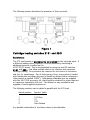
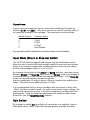
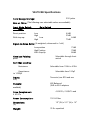
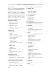
VK-P12SE
WARRANTY REGISTRATION FORM
Unit Serial Number:
_______________________________________
Customer Name:
_______________________________________
Address:
_______________________________________
_______________________________________
Date of Purchase:
_______________________________________
Purchased From:
Dealer Name:
_______________________________________
Address:
_______________________________________
_______________________________________
IMPORTANT NOTE:
In order to receive the full five-year product warranty, please
mail this completed form together with a copy of your sales
receipt to Balanced Audio Technology at the address below,
within thirty days of purchase.
Failure to do so will result in the product being warrantied for
one year from the date of manufacture.
1300 First State Blvd. Wilmington DE 19804 Tel: 302-999-8855 Fax: 302-999-8818
VK-P12SE
Special Edition
Balanced Phono Stage
Owner's Manual
1300 First State Blvd. Wilmington DE 19804 Tel: 302-999-8855 Fax: 302-999-8818
NOTE:
Your VK-P12SE Phono Preamplifier was preset at the factory to the
following configuration:
Input Mode:
Direct
Gain:
High
Input Resistive Loading:
47kΩ
Input Capacitive Loading:
None
Please refer to the chapter on configuration switch setting for information
on optimizing the unit parameters.
Introduction
Thank you for your purchase of the Balanced Audio Technology Special
Edition VK-P12SE balanced phono stage. Please read this owner's manual to
obtain the full benefit of the VK-P12SE in your system. It will provide you with
the needed safety information and operating procedures for this exceptional
unit.
WARNINGS :
To prevent the possibility of serious injury, electrical shock or fire:
DO NOT operate with the cover removed.
DO NOT expose to rain or moisture.
DO NOT defeat the ground power-plug.
DO NOT replace fuse with anything other than the same type and rating as
supplied by the factory.
Package Contents
Included in the box should be the following:
Description
Quantity
VK-P12SE Balanced phono stage
Power Cord
1
Spare Fuse (See Fuse Protection)
XLR Input Shorting Plugs
2
Torx Wrench (T-10)
Spare Top Cover Screws
5
User’s Manual
1
1
1
1
Save all the packaging material in a safe dry area for the unlikely event
that you need to return the VK-P12SE to the factory for service.
Reseating Tubes
Normally, reseating tubes upon delivery is not required. However, if
any tubes have noticeably drifted out of position due to unusually high
transportation stress, it will be advisable to reseat the tubes. Use the
supplied Torx wrench to remove the top cover.
Reseat the tubes in their sockets and reinstall the top cover.
NOTE: When using the Torx wrench, make sure it is fully inserted so that the
screw head is not stripped.
Physical Placement
It is recommended that you provide for at least 6" of free space around the
unit for proper ventilation.
Mount the unit on a hard surface with proper ventilation underneath.
Do not stack the VK-P12SE phono stage on top of other units, nor vice
versa.
General Description of VK-P12SE Phono Preamplifier
The VK-P12SE balanced all-tube phono stage is designed to provide the
maximum possible performance while operating in conjunction with the wide
verity of phono cartridges available today. The unit offers unmatched
versatility in system configuration by providing the following features:
- Wide range of user-selectable gains from 44dB to 79dB (See
Specifications section
for choices)
- Built-in high-quality step-up transformers that can be used with very
low output
phono cartridges.
- Selectable cartridge loading for both resistance and capacitance
- Absolute polarity reversal switch
Please refer to the Configuration Switches section of this manual for
information on how to configure the VK-P12SE phono stage for optimal
performance in your system.
Connecting the VK-P12SE to Your System
Cartridge Input
The back panel of the VK-P12SE phono stage is equipped with two sets of
input connectors:
RCA input connectors
XLR input connectors
Either set can be used for connection. This gives the user the flexibility in
connecting the phono cartridge cable to the VK-P12SE. Whenever possible,
the balanced XLR inputs should be used. They provide the best possible
performance. Please contact the factory regarding the best ways of
connecting your tonarm to the VK-P12SE.
NOTE: Connecting to RCA Inputs:
When connecting your cartridge to the VK-P12SE RCA inputs, it is
necessary to install the supplied shorting plugs into the unused
XLR inputs.
Output Connection
The VK-P12SE is equipped with XLR output connectors. Any high quality set
of balanced interconnects can be used to connect the VK-P12SE to your
balanced preamplifier.
Single-ended preamplifiers can be connected to the VK-P12SE output
through the use of XLR-to-RCA adapters, available from BAT.
Description of Controls
Power Switch
The power switch toggles between two positions: OFF and ON. Putting the
unit in the OFF position (even for a short period of time) will reset the soft
start and mute circuits.
The VK-P12SE will then require about 45 seconds to return back to normal
operation.
When you turn the unit ON, the VK-P12SE will automatically go through a
gentle power-on sequence. At the end of this sequence the unit will
automatically unmute. However, since the source volume may be unknown at
this time, it is advisable to turn the volume control on your preamplifier fully
counterclockwise and place the mute switch in the "Mute" position before
turning the VK-P12SE ON.
Phase Switch
The Phase switch on the front panel of the VK-P12SE allows the user to
compensate for recordings made in inverted polarity. It toggles between
two positions: 0o and 180o. The LED will light when the unit is put in its 180o
state. With this switch in its 0o position, the VK-P12SE performs as a noninverting preamplifier. Switching into the 180o position will invert the
absolute phase of the signal.
It is important to note, however, that in both 0 o and 180 o
positions of the Polarity switch the signal passes through exactly
the same signal path elements and components.
Output Muting
The output of the VK-P12SE phono stage has a mute relay that disables it for
about 45 seconds every time the unit is turned ON.
When the unit is powered up it automatically self-mutes until the proper
operating points of the circuitry are reached. It will then go into normal play
mode.
Changing the power switch position from ON to OFF even for short time, will
make the unit reset its power sequencing circuit and mute its output. It will
then require about 45 seconds for the unit to become operational again.
Configuration Switches
WARNINGS:
Please make sure that the VK-P12SE is turned OFF and your
preamplifier is in MUTE before changing the state of any internal
configuration switches in VK-P12SE.
Hazardous voltages are present on the unit’s printed circuit
board. DO NOT operate the VK-P12SE with its top cover removed.
This section describes the setting of internal configuration switches that are
located inside the VK-P12SE phono preamplifier. In order to access these
switches, do the following:
1. Turn the VK-P12SE OFF and disconnect the power cord from the power
line receptacle.
2. Remove the top cover, using the supplied Torx T-10 wrench.
Figure 1 depicts the locations of the VK-P12SE internal configuration
switches. These include:
1. Left and right channel cartridge loading switches S101 and S201
2. Direct/Step-Up input mode switches S102 and S202
3. Gain switch S2
The following section describes the operation of these controls.
Figure 1
Cartridge loading switches S101 and S201
Resistance:
The 47K load resistor is permanently connected to the cartridge input. If
a different loading value is desired, it can be obtained by switching in
additional resistors, installed on the
VK-P12SE PC board. This is accomplished by using the two DIP switches,
S101 and S201, that allow multiple choices for resistive and capacitive
cartridge loading. Four positions are reserved for the choice of resistance
and four for capacitance. Out of each group of four, one position is loaded
with female pins and allows the user to install any desired value component
(this position is marked “USER”). Gold-plated solderable pins are supplied
with the VK-P12SE accessory kit, that should be attached to either resistors
or capacitors supplied by the user. This allows for easy installation and
upgrade of user-supplied components.
The following resistors can be added in parallel with the 47K load:
Switch position
Resistor Value
1
2
3
4
100 Ohm
1K
10K
User-Defined
Any parallel combination of the these values is also allowable.
Capacitance:
Various values of capacitors can be connected in parallel to the input via
switches S101 and S201. With these switches in the OFF position, there is
no capacitive loading to the cartridge. The capacitance choices include:
Switch Position
Capacitor Value
5
6
7
8
100pF
470pF
1000pF
User-Defined
Any possible parallel combination of these values is also allowable.
Input Mode (Direct or Step-Up) Switch
The VK-P12SE comes equipped with internal step-up transformers, which
allow the user to achieve the best possible signal-to-noise ratio and dynamic
range in any system configuration, including systems with very low output
moving coil cartridges (down to .1mV or less).
By changing the position of the S102 and S202 switches, user may choose
between Direct and Step-Up input modes. In Direct mode the cartridge is
connected directly to the vacuum tube amplification stage. In the Step-Up
mode the cartridge signal is routed through the
step-up transformer, in order to boost it before it reaches the amplification
stage. This allows for an additional gain of 20dB.
It is recommended that for phono cartridges with the output of more than
.25mV, the Direct mode be used. For sources with lower output voltage, the
user should experiment in order to find the combination, providing the best
performance. Using the Step-Up transformers will usually provide a lower
noise floor (see the Specifications chapter).
Gain Switch
By moving the switch S2 from High to Low position, the amplifier’s gain is
reduced by about 15dB. While the High gain position provides the most
universal setting, it may be desired to reduce the overall system gain when
using some high output phono cartridges.
Fuse Protection
A blown fuse in the VK-P12SE is an indication of a serious problem. If a
replacement fuse fails as well, no further attempts should be undertaken.
Please contact the factory for professional service.
The proper fuse ratings are as follows:
For 100-120 VAC Units:
2A 250V Slow Blow
For 200-240 VAC Units:
1.5A 250V Slow Blow
WARNING:
Factory supplied fuses should be only replaced with the same type
and rating parts.
Servicing
The Balanced Audio Technology VK-P12SE should require no service other
than changing tubes to maintain its high performance. The vacuum tubes
used in the VK-P12SE are high quality 6922’s and 6SN7’s rated for
approximately 5000 hours of use. Please direct any further service inquiries
to the factory.
Cleaning
To remove dust, occasionally wipe the front and top surfaces of your VKP12SE with a damp soft cloth. If fingerprints appear, you may use a mild,
non-alkaline soap solution. Do not use abrasive cleaners, as they may
damage the fine finish of the unit.
VK-P12SE Specifications
Total Energy Storage:
200 joules
Gain at 1kHz: (The following user-selectable values are available)
Input Mode Switch
Gain
Direct position:
With step-up:
Gain Switch
Low
High
High
44dB
59dB
Low
79dB
64dB
Signal-to-Noise Ratio: (A-weighted, referenced to 1mV)
Low position
High Position
With Step-Up
Absolute Polarity:
panel
75dB
78dB
86dB
Selectable through front
switch
Cartridge Loading:
Resistance:
Capacitance:
to 1000pF
Selectable from 100Ω to 47kΩ
Selectable from 100pF
Inputs:
XLR)
Two sets (one RCA and one
Outputs:
XLR Balanced
(XLR-to-RCA adapters
available)
Tube Complement:
4 6C45’s
Power Consumption:
Dimensions:
(D)
Weight:
4 6922’s, 2 6SN7’s and
150 VA Max
19” (W) x 5.5” (H) x 14”
35 lb. unpacked
Terms and Conditions
Five Year Limited Warranty
1. Limited Warranty
Upon receipt of the attached warranty registration form, Balanced Audio Technology
warrants the purchased product to be free from manufacturing, materials, and workmanship
defects for five years from date of original purchase, excepting vacuum tubes, subject to
the following conditions. Failure to return the enclosed registration form within 30
days from original purchase will result in a warranty period of one year from
the date of manufacture.
2. Vacuum Tubes
Vacuum tubes (including replacements under warranty) are warranted for one year from the
date of the original VK-P12SE purchase.
3. Limited to Original Purchaser
This warranty is for the sole benefit of the original purchaser of the covered product, and
may not be transferred to a subsequent purchaser of the product.
4. Conditions and Limitations
This warranty is subject to certain conditions and limitations, as follows. This warranty is
void and inapplicable if the product has not been used in accordance with the instructions
found elsewhere in this manual, or if it has been misused or abused, damaged by accident or
neglect, or in transport once in possession of the purchaser. The warranty is also void if the
product has been repaired, modified, or tampered with by anyone other than Balanced Audio
Technology or its specifically authorized agents.
5. Remedy
If this product contains a materials, manufacturing, or workmanship defect that cannot be
repaired at the dealership where the product was purchased, it must be packed in original
packaging and returned to Balanced Audio Technology via insured freight, at the owners
expense. If replacement packaging materials are required, they will be supplied by the
factory at a nominal charge. Returned products must be accompanied by a written
description of the defect, and a return authorization number (available from
the factory via phone or fax). Upon receipt of defective product, Balanced Audio
Technology agrees to repair the product without charge for parts (except vacuum tubes if
the unit is more than one year old), or labor. The product will then be returned via prepaid,
insured freight, with carrier at the sole determination of Balanced Audio Technology. This
constitutes the purchasers sole remedy.
6. Design Changes
Balanced Audio Technology reserves the right to modify its products or change
specifications at any time without obligation or liability to previous purchasers.
7. Miscellaneous
Any implied warranties relating to the above product shall be limited to the duration
of this warranty. This warranty does not extend to any incidental or consequential
costs or damages to the purchaser. This warranty gives you specific legal rights. You
may also have other rights which vary from state to state.