1
Original
Operating instruction
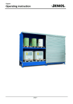
Systemcontainer
130406_BA_DE_005
page 1
Sep. 2010
Table of contents
1
General Instructions ........................................................................................................................................... 3
1.1
1.3. Legend, Explanation of symbols......................................................................................................... 3
1.2
Basic safety instructions ............................................................................................................................ 3
2
Safety instructions .............................................................................................................................................. 4
3
Intended use....................................................................................................................................................... 5
4
Product description............................................................................................................................................. 6
4.1
Design........................................................................................................................................................ 6
4.2
Technical Data........................................................................................................................................... 8
4.3
Approval..................................................................................................................................................... 9
5
Transport ..........................................................................................................................................................10
5.1
Transport securing devices and handling by crane.................................................................................10
5.2
Transport by fork-lift truck ........................................................................................................................11
6
Erection / Commissioning.................................................................................................................................11
6.1
Erection conditions ..................................................................................................................................11
6.2
Additional conditions for the storage of flammable substances outdoors. ..............................................11
6.3
Alignment and anchoring in the ground...................................................................................................12
6.4
Earthing ...................................................................................................................................................16
7
Operation..........................................................................................................................................................16
8
Malfunctions .....................................................................................................................................................17
9
Maintenance and Repair ..................................................................................................................................17
10
Putting out of operation................................................................................................................................18
11
Disposal .......................................................................................................................................................18
11.1
Approval...................................................................................................................................................19
11.2
Certificate supervision contract ...............................................................................................................21
11.3
Inspection report of specialist firm ...........................................................................................................22
11.4
Certificate SLV.........................................................................................................................................24
11.5
Control- and maintenance-plan ...............................................................................................................26
130406_BA_DE_005
page 2
Sep. 2010
1
General Instructions
1.1
1.3. Legend, Explanation of symbols
The following safety symbols are used in these operating instructions. Above all, these symbols are intended to
draw the attention of the reader to the adjacent safety instructions.
This symbol indicates that there are hazards to the life and health of persons.
The symbol indicates that there are hazards for the machine, material or environment.
This symbol identifies information provided to improve understanding of the product and correct
handling of the product.
This symbol warns of dangerous electrical voltage within the working area (e.g. electrical
distributors, terminal boxes, etc.)
This symbol warns of hazards caused by explosive atmospheres.
This symbol indicates suspended loads and their concomitant dangers.
This symbol indicates a possible risk of crushing
This symbol indicates a possible risk of crushing body parts (especially hands) by moving machine
parts or machine parts that are closing.
SEPARATE
INSTRUCTIO
NS
1.2
This point refers to additional operating instructions or regulations (enclosed or delivered
separately) required for operation or maintenance of accessories; these must be read and carefully
observed.
(safety instructions referring to these must always be observed).
Basic safety instructions
Keep this user manual in a safe place. It has been designed for practical use and should be
available to the user on site.
130406_BA_DE_005
page 3
Sep. 2010
This user manual applies to the Systemcontainer. It contains all the information needed regarding
correct startup, trouble-free operation, maintenance, removal from service and disposal.
The instructions in this user manual must be carefully followed and adhered to.
Any person who is involved in the installation, use, servicing or repair of the product is required to
have familiarized him/herself with the contents of the user manual and to have been trained and
instructed in its handling.
These instructions for use do not absolve the operator from the duty to issue special operating
instructions in accordance to the German GefStoffV and BetrSichV (hazardous substances regulation
and the regulation for industrial health and safety). The user manual us based on the safety data
sheet and a risk assessment. The prohibition regarding the storing together of certain substances
must be adhered to.
No changes, extensions or modifications may be made to the product without the manufacturer's
written authorisation.
National regulations and safety regulations have to be adhered to.
2
Safety instructions
The storage system may only be operated by skilled and instructed personnel. Potential hazards
have to be identified.
Unauthorized people are not allowed to enter the storage system.
The storage system may only be used for its intended purpose.
Handling of hazardous substances is only allowed while wearing the specified protective
equipment.
If the storage system is damaged, it has to be repaired immediately by an approved company
while observing the required safety measures.
In case of any damage the storage system must be put out of service.
There is the risk of bruises when using the door.
Only store materials for which the storage is designed.
The trading units for the materials must comply with the provisions for the Transportation of
Dangerous Goods.
130406_BA_DE_005
page 4
Sep. 2010
The trading units may only be opened for filling and emptying. They are only allowed to be
dispensed above the sump.
The following regulations and instructions, latest issues, have to be observed:
- BGV A1 and BGR 234
- The information leaflet “Rules of operation and conduct for the storage of water-hazardous
liquids" (put it up at a clearly visible position!)
- Construction supervision approval (if available)
Fire, naked flames or smoking are not allowed.
The system has to be checked regularly. For this purpose, refer to the Control and Maintenance
Plan
3
Intended use
The Systemcontainer is a storage system used to store hazardous substances and flammable liquids of the
classes R10, R11 and R12 in accordance with the ordinance on hazardous substances (later than 01 December
2010, these classes will be called H 224, H 225 and H 226 acc. to GHS).
The specified total volumes of the storage system must not be exceeded. The load capacity of the storage system
in the data sheet/on the type plate must also be observed. Make sure that the substances are only stored on the
grids. During storage, the total permissible storage volumes as well as the maximum permissible storage volume
of the largest storage unit must be met and observed, depending on the provided sump capacity.
Additionally, before use and after any change of the type of the stored media, it will be necessary to prove that the
material of the sump is resistant to the medium to be stored.
This proof can be provided:
- by DIN 6601 or
- by the BAM list
- as a proof of experience
Drums may only be placed into the storage system or removed from it, or lifted down, using suitable equipment
(e.g. drum grippers).
Substances are only permitted to be stored together when the risk assessment indicates that there are no hazards
caused by possible reactions or physical influences. Otherwise, the substances must be stored separately. The
substances must be stored in a way that all trade units and the sump can be viewed.
Packagings and trading units must comply with the provisions for the transportation of dangerous goods.
130406_BA_DE_005
page 5
Sep. 2010
4
Product description
4.1
Design
The System Containers are designed as follows:
-
Frame structure made of rolled box sections according to structural analysis.
Side walls and roof made of galvanized steel sheets
Rear panels made of galvanized trapezoidal sheet sections
Sump made of steel (material S235 JR, material number: 1.0038 according to DIN EN 10025-2) and tested
using a leak test according to DIN EN-571-1
Optional sump insert made of stainless steel or plastics (PE HD)
Optionally, the front can be equipped with wing door, sliding door or roller shutter.
The earth connection of the basic body is ensured.
The surface of the steel parts is galvanized or one-colour painted on a 2K-PUR basis.
Foot plates are mounted to fix it to the bottom.
Model codes
3 G 3 14. O ST (Example)
Locking element
TE
ST
RT
= Wing door
= Sliding door
= Roller shutter
O
I
= with roof
= without roof
Lining
Container depth in m x 10 (without locking element)
Container width in m (rounded off to a whole number)
Type of storage
A
G
K
P
= Horizontal storage of drums
= Vertical storage of drums
= Storage of CTCs (IBCs)
= Storage of trading units and pallets
Number of storage levels
130406_BA_DE_005
page 6
Sep. 2010
130406_BA_DE_005
page 7
Sep. 2010
4.2
Technical Data
System Container, G model for vertical storage of drums, outdoors
Model
Shelf
width
(mm)
Shelf
depth
(mm)
1G 314
2G 314
3000
2 x 3000
3G 326
1G 626
1400
2 x 1250
2 x 1270
2 x 3000
1260
1900
25200
3470
7800
1750
15600
2220
1 x 2640
15600
3 x 1250
1800
2370
22800
2850
4200
16800
3 x 1250
2 x 1250
3G 626
8400
8400
1 x 2640
3000
Net weight
(kg)
1050
1 x 2640
1500
Shelf
load
(kg)
4200
12600
3 x 1250
1G 326
Net load
(kg)
3 x 1250
2 x 1250
3G 614
2G 626
750
2 x 1250
1310
1G 614
2G 326
Sump
capacity (l)
1 x 2640
3G 314
2G 614
Shelf
height
(mm)
3900
2800
3400
31200
4175
46800
6150
System Container, P model for the storage of pallets, outdoors
Model
2P 414
3P 414
2P 814
3P 814
1P 1214
2P 1214
Shelf
width
(mm)
Shelf
depth
(mm)
Sump
capacity (l)
2 x 1250
3900
2 x 3900
Shelf
height
(mm)
1100
3 x 1250
1310
2 x 1250
2100
3 x 1250
2640
3 x 3900
3200
2 x 1250
Net load
(kg)
Shelf
load
(kg)
Net weight
(kg)
10920
1580
16380
2210
21840
32760
5460
2880
4100
16380
4400
32760
5000
System Container, K model for the storage of CTCs/IBCs, outdoors
Model
1K 214
2K 214
1K 414
2K 414
1K 514
2K 514
Shelf
width
(mm)
2700
3380
2 x 2700
130406_BA_DE_005
Shelf
depth
(mm)
Shelf
height
(mm)
1310
1 x 2570
Sump
capacity (l)
2 x 1500
1 x 2570
2 x 1500
1 x 2570
2 x 1500
page 8
1000
1180
2000
Net load
(kg)
4725
9450
5915
11830
9450
18900
Shelf
load
(kg)
4725
5915
4725
Net weight
(kg)
1120
1400
1130
1600
1970
2400
Sep. 2010
1K 714
2K 714
1 x 2570
2 x 3380
11830
2400
2 x 1500
23660
5915
2110
2950
System Container, A model for the horizontal storage of drums, outdoors
Model
Shelf
width
(mm)
2A 314
3A 614
Shelf
height
(mm)
Sump
capacity
(l)
2 x 1130
3000
3A 314
2A 614
Shelf
depth
(mm)
1340
2 x 3000
470
3 x 750
2 x 1165
1000
3 x 750
Load
capacity
(kg/m2)
Shelf
load
(kg)
Net weight
(kg)
1150
350 kg/drum
platform
1250
2000
2330
System Container, H model, for variable storage, outdoors
Model
Shelf
width
(mm)
Shelf
depth
(mm)
Shelf
height
(mm)
Sump
capacity (l)
Net load
(kg)
Shelf
load
(kg)
Net weight
(kg)
2H 1214
3900
1310
1500
3200
38320
6385
5300
Net load
(kg)
Shelf
load
(kg)
Net weight
(kg)
System Container, G-I model for the vertical storage of drums, indoors
Model
Shelf
width
(mm)
Shelf
depth
(mm)
Sump
capacity (l)
1 x 1250
2G 314.I
1 x 500
3000
2 x 1250
3G 314.I
1310
2G 614.I
2 x 3000
3G 614.I
4.3
Shelf
height
(mm)
1 x 500
12600
1450
4200
1 x 1250
2 x 1250
960
750
1 x 500
1 x 500
8400
16800
2600
25200
2630
1500
Approval
System Containers are admitted for use by the local construction authority and local water
authority with No. Z-38.5.120.
130406_BA_DE_005
page 9
Sep. 2010
There are proofs of stability available for the System Container which are the basis of
the approval.
Load assumptions:
5
Wind load:
0.5 kN/m2according to DIN 1055
(refer to tables: Dimensions and loads)
Snow load:
0.96 kN/m2according to DIN 1055
Transport
Before transport, make sure that the permissible total height and width are not exceeded.
5.1
Transport securing devices and handling by crane
Only empty System Containers are allowed to be transported!
Before starting transport activities, fasten the container on the specified lashing points.
To transport the System Containers with crane eyes, the lifting angle of the ropes may not exceed
60°. Refer to the image "Lashing of ropes/chains".
130406_BA_DE_005
page 10
Sep. 2010
Container models:
214/314/ 414/ 326/ 426
Container models:
514/ 614/ 714/ 814/ 626/ 826
Image: Lashing of ropes/chains
5.2
Transport by fork-lift truck
System Containers may only be unloaded and transported with fork-lift trucks of sufficient load capacity. Make
sure that the forks are long enough to avoid tipping over.
Consider the maximum load capacity of the fork lift!
6
Erection / Commissioning
6.1
Erection conditions
System Containers may only be placed on even and paved surfaces. The foundation provided by the customer
must be able to discharge the indicated loads. The selection of concrete with regard to bearing capacity, fitness for
use and durability compliant to DIN EN 206 must be determined by the planner in accordance to the local
requirements (refer also in the foundation plan).
It may be required that an expert or a specialist firm has to prove the system before the
commissioning.
6.2
Additional conditions for the storage of flammable substances outdoors.
130406_BA_DE_005
page 11
Sep. 2010
For the erection of System Containers, the following installation instructions (refer to images 1 - 3) have to be
observed and kept to ensure natural ventilation:
Safety distances to the adjacent buildings have to be kept and protecting strips must be
established.
Flammable materials may only be stored passively in naturally ventilated System
Containers.
Image 1
Formation of blocks with max. 4 containers;
2 pieces each, in 2 rows after another
Image 2
Containers in a row without
limitation of piece number!
Image 3
2 containers placed next to each other
in a row against a wall!
6.3
Alignment and anchoring in the ground
130406_BA_DE_005
page 12
Sep. 2010
1. The container is set up at the desired place. To be able to reach the rear fixing points, a distance of 60 cm
should be kept to other buildings and the other facilities.
2. Remove the transport securing devices of the doors. In case of wing doors, they are in the middle - at the
bottom. In case of sliding doors, each sliding door element is secured outside, at the bottom, and additionally
outside, at the top.
Wing door - Transport securing device
Sliding door - Transport securing device, at the
bottom
3. The container has to be aligned horizontally and vertically using a spirit level. Also ensure that the doors are in
alignment.
Image: Correct position of the door alignment marks
For the alignment use shims which are laid under the foot plates.
4. After the container has been aligned, the dowel boreholes are to be drilled. Please find the required boreholes
in the images below.
Position and number of composite anchors, refer to Images 1 - 3:
130406_BA_DE_005
page 13
Sep. 2010
Image 1
Container models: 214/ 314/ 414/ 326/ 426-O
and OTE
Number of composite anchors: 4
Image 2
Container models: 514/ 614/ 714/ 814/ 626/ 826O, OTE and ORT
Number of composite anchors: 6
Image 3
Container models: 614/ 714/ 814/ 626/ 826-OST
Number of composite anchors: 7
5. Apply the dowels according to the manufacturer's instructions. Attach locking nut and washer and fasten the
nut.
1
2
3
1
Down comer - container
2
Foot plate
3
Screw connection
4
Composite anchor M16
5
Fixing nut M16
6
Washer
130406_BA_DE_005
4
5
6
page 14
Sep. 2010
Image: Detail of floor anchor with foot plate
130406_BA_DE_005
page 15
Sep. 2010
6.4
Earthing
For the storage of flammable substances, the System Containers have to be connected to earth (refer to image).
To do this, use the VbF accessory kit (item no.: 138099).
The earth connector at the customer's side is to be connected to the VbF accessory kit. You can also connect
round or flat steel earth connections.
Detail: Installation of flat-steel earth-connection
Detail: Installation of round-steel earth-connection
7
Operation
•
Open the doors for loading or unloading the stored goods. Secure the wing doors using
the storm hooks.
• In case of sliding doors make sure that no objects are in the closing edge when closing
the door.
• Use a suitable lifting gear (e.g. fork lift truck with drum grippers) to place the containers on
the grid or to unload them.
• When storing metal containers place them carefully on the grid (speed 1 m/s) to prevent
any possible sparks.
130406_BA_DE_005
page 16
Sep. 2010
•
•
During storage or removal, the trading units must be secured against tipping over. For
transport, also secure the trading units against tipping over.
When loading/unloading, pay attention to the shelf depth (refer to the Technical Data).
•
Store the goods that way that the sump can always checked visually from one position.
•
After the storage system has been used, close the doors immediately.
•
Lock the doors to avoid unauthorized access.
•
Observe the safety instructions.
•
Remove inadmissible snow loads from the storage system.
8
Malfunctions
Error
Cause
Action
Liquid in the sump
Rainwater
Get the storage system sealed.
Dispose the liquid from the sump
without damaging the environment.
Leaky container
Dispose the liquid from the sump
without damaging the environment.
Check the sump for damages.
Bent grid
Load too high
Replace the grid.
Check the storage system for
damages.
Doors are difficult to move
Hinges, rolling elements
Lubricate the components.
If it does not become better, replace
the components.
For questions or repairs contact our Denios specialists.
9
Maintenance and Repair
Switch the power supply off (if it exists) before starting maintenance and repair works and secure it
against accidental switching on by taking appropriate measures.
•
Please find hints for maintenance and repair in the Control and Maintenance Plan attached to these
operating instructions.
•
We recommend ordering a yearly maintenance service by the DENIOS AG.
•
Before performing the maintenance or repair works, cut off the access to the storage system for
unauthorized people! Post or place an information sign which informs about the maintenance and repair
works!
130406_BA_DE_005
page 17
Sep. 2010
•
When exchanging parts use only original replacement parts from the manufacturer!
10
Putting out of operation
If the storage system is damaged it has to be put out of service and labelled accordingly.
11
Disposal
The container is comprised of various components and parts which must be disposed or or recycled in compliance
to the local and legal regulations.
Before the disposal, any hazardous residue must be thoroughly cleaned off from the container!
Disassemble or dismount the single components of the container and arrange the components into the following
groups
•
Steel
•
Light metals
•
Non-ferrous heavy metal
•
Plastic
•
Electronic components and cable
•
Building materials/insulation material
Ensure that all of these components are disposed of correctly and professionally, and are thereby a part of the
recovered substance cycle.
130406_BA_DE_005
page 18
Sep. 2010
11.1
Approval
130406_BA_DE_005
page 19
Sep. 2010
130406_BA_DE_005
page 20
Sep. 2010
11.2
Certificate supervision contract
130406_BA_DE_005
page 21
Sep. 2010
11.3
Inspection report of specialist firm
130406_BA_DE_005
page 22
Sep. 2010
130406_BA_DE_005
page 23
Sep. 2010
11.4
Certificate SLV
130406_BA_DE_005
page 24
Sep. 2010
130406_BA_DE_005
page 25
Sep. 2010
11.5
Control- and maintenance-plan
130406_BA_DE_005
page 26
Sep. 2010