1
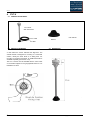
USERS MANUAL CV7 CV7 Standard CV7-V CV7-C CV7SF LCJ CAPTEURS 25 Allée des Cinq Continents ZA le ChêneFerré 44120 VERTOU – France Tél : 33(0)2 40 05 08 55 Email :[email protected] www.lcjcapteurs.com SIRET : 42493307500022 / RCS Nantes VAT : FR17424933075 Copyright © 2014 LCJ CAPTEURS EN 55022 EN55024 CV7 manual 2014 / English 1 CONTENT: 1 GENERAL INFORMATION AND SAFETY GUIDELINE ................................................................................................. 4 1.1 GENERAL RECOMMENDATIONS .................................................................................................................... 4 1.2 MAINTENANCE AND REPAIR .......................................................................................................................... 4 1.3 DISPOSAL ......................................................................................................................................................... 4 1.4 USE OF THIS MANUAL ..................................................................................................................................... 5 1.5 VALIDITY OF THIS MANUAL ............................................................................................................................ 5 1.6 LIMITED WARRANTY ........................................................................................................................................ 5 1.7 RESPONSABILITY ............................................................................................................................................ 5 2 INSTALLATION OF A CV7 WIND SENSOR ................................................................................................................... 6 2.1 TYPICAL INSTALLATION OVERVIEW .............................................................................................................. 6 2.2 SENSOR ALIGNEMENT .................................................................................................................................... 6 2.3 CONNECTIONS ................................................................................................................................................. 6 2.4 SET UP / COMMISSIONING.............................................................................................................................. 6 3 CV7 Standard .................................................................................................................................................................. 7 3.1 CONTENT OF DELIVERY ................................................................................................................................. 7 3.2 SENSOR ALIGNEMENT .................................................................................................................................... 7 3.3 DIMENSIONS..................................................................................................................................................... 7 4 CV7-V ............................................................................................................................................................................... 8 4.1 CONTENT OF DELIVERY ................................................................................................................................. 8 4.2 SENSOR ALIGNEMENT .................................................................................................................................... 8 4.3 DIMENSIONS..................................................................................................................................................... 8 5 CV7-C............................................................................................................................................................................... 9 5.1 CONTENT OF DELIVERY ................................................................................................................................. 9 5.2 SENSOR ALIGNEMENT .................................................................................................................................... 9 5.3 DIMENSIONS..................................................................................................................................................... 9 6 CANBUS OPTION ......................................................................................................................................................... 10 6.1 TYPICAL INSTALLATION OVEVIEW .............................................................................................................. 10 6.2 CONNECTIONS ............................................................................................................................................... 10 6.3 COMMISSIONING ........................................................................................................................................... 10 6.4 SENSOR ALIGNEMENT .................................................................................................................................. 10 6.5 CALIBRATION OF THE BAROMETER ............................................................................................................ 10 7 OPTION CANBUS-RM ................................................................................................................................................... 11 7.1 TYPICAL INSTALLATION OVERVIEW ............................................................................................................ 11 7.2 CONNECTIONS ............................................................................................................................................... 11 7.3 COMMISSIONING ........................................................................................................................................... 11 7.4 CALIBRATION OF THE MAST ANGLE SENSOR. MID-SHIP AND MAST ANGLE ENDS ............................. 11 7.5 DIMENSIONS OF THE CANBUS JUNCTION BOX ......................................................................................... 11 8 OPTION ST .................................................................................................................................................................... 12 8.1 TYPICAL INSTALLATION OVERVIEW ........................................................................................................... 12 8.2 CONNECTIONS ............................................................................................................................................... 12 8.3 COMMISSIONING ........................................................................................................................................... 12 8.4 DIMENSIONS................................................................................................................................................... 12 9 OPTION BG ................................................................................................................................................................... 12 9.1 TYPICAL INSTALLATION OVERVIEW ............................................................................................................ 12 9.2 CONNECTIONS ............................................................................................................................................... 12 9.3 COMMISSIONING ........................................................................................................................................... 12 9.4 DIMENSIONS................................................................................................................................................... 12 10 OPTION SIL (NEXUS NX2, SILVA and FI30) .............................................................................................................. 13 10.1 DIMENSIONS................................................................................................................................................... 13 2 Copyright © 2014 LCJ CAPTEURS 11 OPTION BARO .............................................................................................................................................................. 13 13 11.1 DIMENSIONS................................................................................................................................................... 13 12 USB OPTION ................................................................................................................................................................. 14 12.1 CONNECTIONS ............................................................................................................................................... 14 12.2 SPECIFICATIONS ........................................................................................................................................... 14 13 MOUNT ADAPTERS...................................................................................................................................................... 14 13.1 1” ADAPTOR .................................................................................................................................................... 14 13.2 MOUNT ON VERTICAL SURFACE ................................................................................................................. 14 14 SPECIFICATIONS ......................................................................................................................................................... 15 15 ADDENDUM .................................................................................................................................................................. 16 15.1 NMEA0183 INTERFACES ............................................................................................................................... 16 15.2 USING THE CONFIGURATION APPLICATION .............................................................................................. 17 15.3 MOUNTING TEMPLATE .................................................................................................................................. 18 16 CV7SF ............................................................................................................................................................................ 20 16.1 CONTENT OF DELIVERY ............................................................................................................................... 20 16.2 INSTALLATION ................................................................................................................................................ 20 16.3 SENSOR ALIGNEMENT .................................................................................................................................. 20 16.4 CONNECTIONS ............................................................................................................................................... 20 16.5 DIMENSIONS................................................................................................................................................... 20 17 CV7SF-USB ................................................................................................................................................................... 21 17.1 CONTENT OF DELIVERY ............................................................................................................................... 21 17.2 INSTALLATION ................................................................................................................................................ 21 17.3 SENSOR ALIGNEMENT .................................................................................................................................. 21 17.4 USB CONNECTION ......................................................................................................................................... 21 17.5 DIMENSIONS................................................................................................................................................... 21 Copyright © 2014 LCJ CAPTEURS 3 1 GENERAL INFORMATION AND SAFETY GUIDELINE 1.1 GENERAL RECOMMENDATIONS The LCJ Capteurs sensors are Ultrasonic wind vanes/anemometers with accurate factory calibration Install the sensor in in a location free from wind perturbation, usually on the mast head. Prepare the mast head for the mechanical installation. Align the North mark of the bracket in order to have the CV7-C sensor heading to the bow. The sensor’s fine alignment will be obtained with the calibration functions of your instrumentation or the LCJ Capteurs’ software calibration application (see 15.2). When necessary, install the interface junction boxes in a protected and dry location. Run the cable down to the display’s interface, avoiding locations where other cables or equipment may produce electromagnetic interferences (pilot’s ram, radio...) and cutit to the right length. The cable’s length can be adjusted as required providing junctions are made in the state of the art. Turn the power supply off before processing to any wiring work. You can turn power on again only once all installation and wiring is completed. We recommend lightly tinning the wires before connecting them to the screw terminals. Use only genuine accessories supplied by LCJ Capteurs. Do not attempt any modification to the unit. Never paint any part of the unit or alter its surface in any way. Warranty is void in case of non following the instructions of use, repair or maintenance without written authorisation. 1.2 MAINTENANCE AND REPAIR The CV7 sensors do not require any maintenance. Check the connections on a regular basis and make sure the junction boxes are dry and protected. If the Wind pages of your instruments do not display the wind data correctly, refer to the manufacturer’s manual and check the connections before asking for service to your LCJ Capteurs dealer. 1.3 DISPOSAL Equipments marked with the recycling symbol should be processed via a recognized recycling agency. By agreement, they may be returned to the manufacturerDo not mix electronic disposal with domestic or industrial refuse. 4 Copyright © 2014 LCJ CAPTEURS 1.4 USE OF THIS MANUAL This manual serves as a guideline for the safe and effective installation, operation and maintenance of the Ultrasonic Wind Sensors of the CV7 range from LCJ Capteurs. It is recommended to follow carefully the instructions contained herein. Keep this manual in a safe place! 1.5 VALIDITY OF THIS MANUAL All of the specifications, provisions and instructions contained in this manual apply solely to the following products: Part CV7 CV7-V CV7-C CV7SF CV7SF USB Canbus Canbus-RM Option ST Option BG Option baro Option USB Support Vertical Adapt 1’’ Description CV7 standard Ultrasonic Wind Sensor CV7 Ultrasonic Wind Sensor / Vertical CV7 high speed Ultrasonic Wind Sensor/ long carbon vertical arm CV7 / Wireless Ultrasonic Wind Sensor / NMEA0183 receiver CV7 / Wireless Ultrasonic Wind Sensor / receiver for USB CanBusinterface (NMEA2000) CanBus interface for rotating mast (NMEA2000) Interface for Raymarine ST Interface for B&G Junction box with baro sensor Junction box with USB connector Bracket for installation on a vertical surface 1’’standard adapter ( VHF or GPS type) 1.6 LIMITED WARRANTY The LCJ Capteursagainst manufacturing defects for a period of two years from the date of purchase. It is limited to the repair and/or replacement of the product. It does not cover installation costs and shipping costs of faulty units. A proof of purchase may be asked when filling the warranty request which must be received by writing. Once the warranty request is accepted by LCJ Capteurs, the unit must be sent to LCJ Capteurs’ address in France. LCJ Capteurs guarantees that each of their ultrasonic wind sensors are tested and calibrated before despatch. Operations not in compliance with the instructions described in the present manual may result to damage the unit or alter its performances. In such cases, the warranty is void. 1.7 RESPONSABILITY LCJ Capteurs do not accept responsibility for: Consequential damage to the use of a CV7 sensor Possible errors in the manuals and their results Copyright © 2014 LCJ CAPTEURS 5 2 INSTALLATION OF A CV7 WIND SENSOR 2.1 TYPICALINSTALLATIONOVERVIEW This diagram features a CV7 Standard. The typical installation is the same for CV7-V and CV7-C 2.3 CONNECTIONS Red wire + Power Blue wire - Power Yellow wire NMEA TX Green wire NMEA RX Connect to 12 V power supply (10 à 14 VDC). Connect the yellow and green wires to the NMEA input of the instrument. 2.4 SET UP / COMMISSIONING You can use your sensor immediately. Set up such as speed unit, temperature unit and data filtering can be set up with the application “configuration CV7”, downloadable fromwww.lcjcapteurs.com. Refer to 15.2 Utilisation du logiciel de configuration. 2.2 SENSORALIGNEMENT The CV7 sensor must be installed with the “Nord” mark on the bracket aligned to the geographical North for a fix installation on shore and to the bow on a vessel. Fine alignment can be performed with the application “configuration CV7” downloadable fromwww.lcjcapteurs.com 6 Copyright © 2014 LCJ CAPTEURS . 3 CV7 Standard 3.1 CONTENT OF DELIVERY CV7 with oblique arm 25 m cable Oblique bracket User manual 3.2 SENSOR ALIGNEMENT The oblique bracket is meant to be mounted on a horizontal surface. It is usually fixed on the mast head of a sailing boat. The arm points to the bow. CV7 sensor view from below 3.3 DIMENSIONS Copyright © 2014 LCJ CAPTEURS 7 CV7-V 4 CV7-V 4.1 CONTENT OF DELIVERY CV7 sensor With vertical arm 25 m cable User manual Bracket de câble 4.2 SENSOR ALIGNEMENT 4.3 DIMENSIONS A mark below the sensor indicates the alignment. The vertical bracket is designed for mounting on a horizontal surface, usually the mast head on a sailing boat. For mounting on the side of the mast, an additional bracket is available separately (see section 12.2). The CV7-V sensor must be installed with the “Nord” mark on the bracket aligned to the geographical North for a fix installation on shore 8 Copyright © 2014 LCJ CAPTEURS CV7 STANDARD 5 CV7-C 5.1 CONTENT OF DELIVERY CV7 sensor With vertical carbon arm User manual Bracket 25 m cable 5.2 SENSOR ALIGNEMENT 5.3 DIMENSIONS Weight: 200 gr (sensor + arm + bracket) A mark below the sensor indicates the alignment. The vertical bracket is designed for mounting on a horizontal surface, usually the mast head on a sailing boat. For mounting on the side of the mast, an additional bracket is available separately (see section 12.2). The CV7-C sensor must be installed with the “Nord” mark on the bracket aligned to the geographical North for a fix installation on shore 760 mm Copyright © 2014 LCJ CAPTEURS 9 6 CANBUS OPTION 6.1 TYPICAL INSTALLATION OVEVIEW The CanBus option is compatible with all CV7 sensors. Connectors are not supplied. 6.4 SENSOR ALIGNEMENT Fine alignment of the mast sensor can be achieved at sea. Sail on starboard and port to note the correction that needs to be applied from a tack to another. Place the rotary button (S1) in position 1 and use the “+” and “-“ keys to change the value read on the display. Adjust the value accordingly to the difference measured from a tack to another during sea trials. The wind angle will correctly read on the display. 6.5 CALIBRATION OF THE BAROMETER The atmospheric pressure sensor is calibrated against the nearest reference located on the shore level, such as aa weather station. The rotary button (S1) placed on position2 allows calibrating the atmospheric pressure. Once the button is in position 2, the value on the display can be adjusted using the “+” and “-“ keys to match the reference. Make sure your display is set to “mb” unit. 6.2 CONNECTIONS The CV7must be set for NMEA0183 interface (factory set). The CV7ultrasonic sensor is powered by the bus network.Open the junction box to access the connectors. The CanBus option allows connecting a CV7 to any instrument system featuring a NMEA2000 compatible interface. PGNs sent by the option: 59392, 60928, 126464, 126996, 130306, 130311, 130314 PGNs processed by the option: 59392, 59904; 60928 Power consumption : 2 LAN 6.3 COMMISSIONING Refer to the connected instruments’ manual for pages setup and all functions related to wind and atmospheric pressure functions.Once all wiring and connections are completed, turn the power on and check the alignment. It may be adjusted from your instrument’s setup menu. Alternatively, this can be done directly from the CanBus. 10 Copyright © 2014 LCJ CAPTEURS 7 OPTION CANBUS-RM 7.1 TYPICAL INSTALLATION OVERVIEW 7.4 CALIBRATION OF THE MAST ANGLE SENSOR. MID-SHIP AND MAST ANGLE ENDS Use the «- » and « +» keys to change a value that is previously selected with the switch button “S1”. In positions 3 to 6, the values read on the wind displays are the mast angles measures, used for calibration of the mast angle sensor. Calibration process: The CanBus-RM option is compatible with all CV7 sensors. Connectors and mast angle sensor are not supplied. 7.2 CONNECTIONS Open the junction box to access the connectors With the RM option, the CanBus junction box features an extra connection terminal for the mast angle sensor (potentiometer). PGNs sent by the option: 59392, 60928, 126464, 126996, 130306, 130311, 130314 PGNs processed by the option: 59392, 59904; 60928 Power consumption : 2 LAN 7.3 COMMISSIONING Refer to the connected instruments’ manual for pages setup and all functions related to wind and atmospheric pressure functions. Once all wiring and connections are completed, turn the power on and check the alignment. It may be adjusted from your instrument’s setup menu. Alternatively, this can be done directly from the CanBus. Position 6: identification of the potentiometer’s polarity (port-starboard values) Position 5: mid-ship. Place mast in mid-ship position and set the angle to 0° Position 4: port-end. Place the mast in port-end position and set the angle to the relevant value (theoretical or measured) Position 3: starboard-end. Place the mast in starboard-end position and set the angle to the relevant value (theoretical or measured) 7.5 WIND SENSOR ALIGNEMENT Fine alignment of the mast sensor can be achieved at sea. Sail on starboard and port to note the correction that needs to be applied from a tack to another. Place the rotary button (S1) in position 1 and use the “+” and “-“ keys to change the value read on the display. Adjust the value accordingly to the difference measured from a tack to another during sea trials. The wind angle will correctly read on the display. 7.6 CALIBRATION OF THE BAROMETER The atmospheric pressure sensor is calibrated against the nearest reference located on the shore level, such as aa weather station. The rotary button (S1) placed on position 2 allows calibrating the atmospheric pressure. Once the button is in position 2, the value on the display can be adjusted using the “+” and “-“ keys to match the reference. Make sure your display is set to “mb” unit. These values are automatically stored in the device’s memory. They can be fine adjusted after sea trials. 7.7 DIMENSIONS OF THE CANBUS JUNCTION BOX 130x80x30 mm / 150gr Copyright © 2014 LCJ CAPTEURS 11 8 OPTION ST 8.1 TYPICAL INSTALLATION OVERVIEW 8.2 CONNECTIONS This option allows the connection of a CV7 directly to the ROTAVECTA© input on your Raymarine instrument (ST30 Wind, ST50 Wind or ST60 Wind). Power the junction box and the CV7 sensor as indicated below. The green wire coming from the CV7 must be connected to the terminal marked “CV3F +”. The wires coming from the ROTAVECTA© are connected to the B and R terminal with matching colours. The yellow wire coming from the CV7 is dedicated to a serial connection to a PC for use of the setup application (see 15.2). Tight this wire with precaution for future use. Make sure it is correctly isolated. 8.3 COMMISSIONING 9 OPTION BG 9.1 TYPICAL INSTALLATION OVERVIEW 9.2 CONNECTIONS This option allows the connection of a CV7 directly to the MHU input on your B&G. Power the junction box and the CV7 sensor as indicated below.The yellow wire coming from the CV7 is dedicated to a serial connection to a PC for use of the setup application (see 15.2). Tight this wire with precaution for future use. Make sure it is correctly isolated. 9.3 COMMISSIONING Once all connections are completed, refer to the Raymarine manual for the sensor’s alignment. Once all connections are completed, refer to the B&G manual for the sensor’s alignment. 8.4 DIMENSIONS Dimensions : 131 x 58 x 37 mm 9.4 DIMENSIONS Dimensions : 131 x 58 x 37 mm 12 Copyright © 2014 LCJ CAPTEURS 10 OPTION SIL (NEXUS NX2, SILVA and FI30) 11 OPTION BARO 11.1 Screw terminal 11.2 10.1 DIMENSIONS Dimensions : 131 x 58 x 37 mm Copyright © 2014 LCJ CAPTEURS 11.3 DIMENSIONS Dimensions : 131 x 58 x 37 mm 13 12 USB OPTION 12.1 12.2 CONNECTIONS The junction box features a screw terminal and a standard USB cable. Open the box to complete the connections. The USB junction box is powered by the USB connection to the PC. Connect the wire coming from the CV7 as indicated on the diagram above. Plug the USB cable to the PC. The driver will automatically be installed by the Windows® system (Windows 7® and above). Alternatively, the latest version of the driver can be downloaded from the technical support section of the website (www.lcjcapteurs.com). It is an executable file. Double-click on the file to launch the installation. Once the CV7 is connected to the USB port, your relevant software will immediately identify the NMEA0183®sentences via an emulated COM port. 13 MOUNT ADAPTERS 13.1 1”ADAPTOR This optional accessory allows mounting a CV7 sensor on any standard antenna mounting bracket. External diameter: 40 mm Height: 50 mm 13.2 MOUNT ON VERTICAL SURFACE CV7-V base is compatible with standard brackets available on the market, such as the GLOMEX on feature on the picture below. . 12.3 SPECIFICATIONS Dimensions: 57 x 43 x 24 mm Weight: 20 g (without cable and connector) Cable length: 1.50 m Standard USB type A connector Screw terminal 14 Copyright © 2014 LCJ CAPTEURS 14 SPECIFICATIONS CV7 CV7-V CV7-C CV7SF Output data signal NMEA© or NEXUS© NMEA© or NEXUS© NMEA© or NEXUS© NMEA© Output update 2 per second 2 per second 4 per second Wind module sensitivity 0.25 Kt 0.25 Kt 0.25 Kt Wind module resolution 0.1 Kt 0.1 Kt 0.1 Kt Wind module dynamic 0.25 to 80 Kt 0.25 to 80 Kt 0.25 to 80 Kt 1 per sec. In daylight1 every 3 seconds Sunrise&sunset, 0.25 Kt 13 second 1 every night et coucher du soleil, 0.1 Kt 1 fois toutes les 13 sec. la nuit 0.25 to 80 Kt Direction sensitivity +/- 1° +/- 1° +/- 1° +/- 1° Direction resolution 1° 1° 1° 1° Power supply 8 to 33 VDC 8 to 33 VDC 8 to 33 VDC photovoltaic cells for transmitter 6.5 to 27 VDC for receiver Electrical consumption 9.5 mA 9.5 mA 9.5 mA autonomous for transmitter 5.8 mA for receiver Operating temperature range without iceing -15°C/55°C -15°C/55°C -15°C/55°C -10°C/55°C Connection line 25 m of cable 4 x 0,22 mm2 25 m of cable 4 x 0,22 mm2 25 m of cable 4 x 0,22 mm2 Radio transmitter 433 mHz Tx power : 10 dbm Message time : 25 ms Interconnection Direct +12 V 0V NMEA©+ NMEA©- Direct +12 V 0 V NMEA©+ NMEA©- Direct +12 V 0 V NMEA©+ NMEA©- Weight of the head 100 g 100 g 100 g Arm Oblique 30 cm arm Alu Ø 12 mm Vertical 30 cm arm Alu Ø 16 mm Vertical 75 cm carbon arm Ø 16 mm Receiver Superheterodyne ASK 433 MHz Sensitivity: -110 dbm Outputs via screw terminal -110gdbm 100 Sortie surbornier à Vertical 30 cm arm vis Alu Ø 16 mm Mounting base Bracket Bracket Bracket Bracket Total weight including arm and bracket 200 g 200 g 200 g 200 g Copyright © 2014 LCJ CAPTEURS 15 15 ADDENDUM 15.1 NMEA0183INTERFACES NMEA0183 : Output on a 4mA current loop. 4800 Bauds, no parity, 1 stop Bit Constant flow at 500 milliseconds (except CV7-C, at 266 milliseconds) Variable fields lengths, comma separator. Sentence prefix: $ End of sentence: CR,LF Examplesof typical sentences output by CV7, CV7-V, CV7-C : $IIMWV,225.0,R,000.0,N,A*38 $WIXDR,C,022.0,C,,*52 $PLCJ,5801,5F01,AA,4253,3341 $PLCJEA870,6D98,C500,0056,AC, « Wind » sentence: $IIMWV,226.0,R,000.0,N,A *0B CheckSum CV7 status.A :correct measure / V : incorrect measure Wind speed unit. N = knots Wind speed Reference Wind direction in degrees « Wind temperature » sentence: $WIXDR,C,022.0,C,,*52 CheckSum Unit°C Value with one decimal Typical sentence for CV7-BARO, CV7-V-BARO and CV7-C-BARO $WIMDA,,I,1.033,B,019.5,C Unit °Celsius Temperature value with one decimal Atmospheric pressure in Bar Sentence for LCJ CAPTEURS technical use only: $PLCJ,AAAA,BBBB,CC,,,,DDDD,EEEE $PLCJEFFFF,GGGG,HHHH,IIII,JJ Logging two minutes of NMEA sentences flow allows to makea proper diagnostic. 16 Copyright © 2014 LCJ CAPTEURS 15.2 USING THE CONFIGURATION APPLICATION Configuration of the CV7 sensor The “Configuration_CV7-C” software can be downloaded from www.lcjcapteurs.com Make the following serial connection: Colour code Function Red wire + power Blue wire - power SubD 9 points 5 (0 V) 2 (RX) Yellow wire Green wire 3,3 KOhms 3 (TX) 1 Extract the file in a folder of your choice and copy the shortcut on the desktop Double-click on the shortcut and select a COM port to use. Power the CV7. Set your configuration from choices offered by the application. Click on the “Programmation CV7” button to save the settings and follow instructions. Copyright © 2014 LCJ CAPTEURS 2 6 3 7 4 8 5 9 17 15.3 MOUNTING TEMPLATE WARNING! Check the scale when printing this document. Measure indications are in millimetres Vertical bracket: 18 Copyright © 2014 LCJ CAPTEURS Oblique bracket: Copyright © 2014 LCJ CAPTEURS 19 16 CV7SF 16.1 CONTENT OF DELIVERY CV7SF sensor With vertical arm User manual Receiver 16.2 INSTALLATION The CV7SF wind sensor is designed for operation outdoor, exposed to natural light. It must be installed in an area free from any air flow perturbation. Choose a location free from any obstacle and situated at least 150 cm from the ground. The radio signal maximum range is 200 meters. Best results are obtained in a 50 meters distance between the sensor and its receiver. The signal can be perturbated by materials such as carbon, aluminium, steel... A minimum distance of 10 meters between the arm and any conductive material is recommended. Specific environments may cause bad reception. Please contact our technical support in that case. 16.3 SENSOR ALIGNEMENT A mark below the sensor indicates the alignment. The vertical bracket is designed for mounting on a horizontal surface, usually the mast head on a sailing boat. For mounting on the side of the mast, an additional bracket is available separately (see section 12.2). The CV7 sensor must be installed with the “Nord” mark on the bracket aligned to the geographical North for a fix installation on shoreUse a compass, taking the deviation in account. 16.4 CONNECTIONS Open the receiver to access the connection terminal. The NMEA0183 data output is connected as shown below: 16.5 DIMENSIONS 16.6 The CV7SF is compatible with the Directive 1999/5/CE "R&TTE" 20 Copyright © 2014 LCJ CAPTEURS 17 CV7SF-USB 17.1 CONTENT OF DELIVERY CV7SF sensor With vertical arm User manual Receiver with cable and USB connector 17.2 INSTALLATION The CV7SF wind sensor is designed for operation outdoor, exposed to natural light. It must be installed in an area free from any air flow perturbation. Choose a location free from any obstacle and situated at least 150 cm from the ground. The radio signal maximum range is 200 meters. Best results are obtained in a 50 meters distance between the sensor and its receiver. The signal can be perturbated by materials such as carbon, aluminium, steel... A minimum distance of 10 meters between the arm and any conductive material is recommended. Specific environments may cause bad reception. Please contact our technical support in that case. 17.4 USB CONNECTION Plug the USBcable to the PC. The driver will automatically be installed by the Windows® system (Windows 7® and above). Alternatively, the latest version of the driver can be downloaded from the technical support section of the website (www.lcjcapteurs.com). It is an executable file. Double-click on the file to launch the installation. Once the CV7 is connected to the USB port, your relevant software will immediately identify the NMEA0183®sentences via an emulated COM port. 17.5 DIMENSIONS 17.3 SENSOR ALIGNEMENT A mark below the sensor indicates the alignment. The vertical bracket is designed for mounting on a horizontal surface, usually the mast head on a sailing boat. For mounting on the side of the mast, an additional bracket is available separately (see section 12.2). The CV7 sensor must be installed with the “Nord” mark on the bracket aligned to the geographical North for a fix installation on shoreUse a compass, taking the deviation in account. The CV7SF is compatible with the Directive 1999/5/CE "R&TTE" Copyright © 2014 LCJ CAPTEURS 21