1
Thor™ VM1 Vehicle-Mount Computer
with Microsoft® Windows® Embedded Standard 2009
User’s Guide
Disclaimer
Honeywell International Inc. (“HII”) reserves the right to make changes in specifications and other information contained in this
document without prior notice, and the reader should in all cases consult HII to determine whether any such changes have been
made. The information in this publication does not represent a commitment on the part of HII.
HII shall not be liable for technical or editorial errors or omissions contained herein; nor for incidental or consequential damages
resulting from the furnishing, performance, or use of this material.
This document contains proprietary information that is protected by copyright. All rights are reserved. No part of this document
may be photocopied, reproduced, or translated into another language without the prior written consent of HII.
© 2011-2014 Honeywell International Inc. All rights reserved.
Web Address: www.honeywellaidc.com
Trademarks
RFTerm is a trademark or registered trademark of EMS Technologies, Inc. in the United States and/or other countries.
Microsoft® Windows, ActiveSync®, MSN, Outlook®, Windows Mobile®, the Windows logo, and Windows Media are registered
trademarks or trademarks of Microsoft Corporation.
Intel® and Atom™ are trademarks or registered trademarks of Intel Corporation or its subsidiaries in the United States and other
countries.
Summit Data Communications, the Laird Technologies Logo, the Summit logo, and “Connected. No Matter What” are trademarks of Laird Technologies, Inc.
Wi-Fi®, WMM®, Wi-Fi Mutlimedia™, Wi-Fi Protected Access®, WPA™, WPA2™ and the Wi-Fi CERTIFIED™ logo are trademarks or registered trademarks of Wi-Fi Alliance.
The Bluetooth® word mark and logos are owned by the Bluetooth SIG, Inc.
Symbol® is a registered trademark of Symbol Technologies. MOTOROLA, MOTO, MOTOROLA SOLUTIONS and the Stylized
M Logo are trademarks or registered trademarks of Motorola Trademark Holdings, LLC and are used under license.
Freefloat, Link*One and Access*One are trademarks of Freefloat, Mölndalsvägen 30B, SE-412 63Gothenburg, Sweden.
RAM® and RAM Mount™ are both trademarks of National Products Inc., 1205 S. Orr Street, Seattle, WA 98108.
Qualcomm® is a registered trademark of Qualcomm Incorporated. Gobi is a trademark of Qualcomm Incorporated.
Verizon® is a registered trademark of Verizon Trademark Services LLC.
T-MOBILE® is a registered trademark of Deutsche Telekom AG.
AT&T® is a registered trademark of AT&T Intellectual Property.
SD and SDHC are trademarks or registered trademarks of SD-3C, LLC in the United States, other countries or both.
SanDisk® and CompactFlash® are trademarks of SanDisk Corporation, registered in the United States and other countries.
Transcend® is a registered trademark of Transcend Information, Inc.
ATP is a trademark of ATP Electronics, Inc.
Acrobat® Reader © 2014 with express permission from Adobe Systems Incorporated.
Other product names or marks mentioned in this document may be trademarks or registered trademarks of other companies
and are the property of their respective owners.
Patents
For patent information, please refer to www.hsmpats.com.
Table of Contents
Chapter 1 - Thor VM1 Agency Information
FCC Part 15 Statement........................................................................................................1-1
FCC 5GHz Statement ..........................................................................................................1-1
EMC Directive Requirements...............................................................................................1-1
Canada, Industry Canada (IC) Notices ................................................................................1-1
COFETEL ............................................................................................................................1-2
ANATEL (Brazil)...................................................................................................................1-2
Vehicle Power Supply Connection Safety Statement ..........................................................1-2
Li-Ion Battery........................................................................................................................1-2
RF Safety Notice ..................................................................................................................1-3
Bluetooth ..............................................................................................................................1-3
Honeywell Scanning & Mobility Product Environmental Information....................................1-3
CE Mark ...............................................................................................................................1-3
Dealer License - Republic of Singapore ..............................................................................1-3
Chapter 2 - Getting Started
Overview ..............................................................................................................................2-1
About this Guide ..................................................................................................................2-1
Out of the Box ......................................................................................................................2-1
Initial Setup for Thor VM1 ....................................................................................................2-2
Hardware Setup .............................................................................................................2-2
Software .........................................................................................................................2-2
Languages ...............................................................................................................2-2
First Boot ..................................................................................................................2-2
Software Setup.........................................................................................................2-2
Quick Mount Smart Dock .....................................................................................................2-2
Components.........................................................................................................................2-3
Front View ......................................................................................................................2-3
Back View with Quick Mount Smart Dock ......................................................................2-4
Access Panels...............................................................................................................2-4
Backlights and Indicators .....................................................................................................2-5
Display Backlight............................................................................................................2-5
Power Management .................................................................................................2-5
Backlight Brightness.................................................................................................2-5
Screen Blanking .......................................................................................................2-5
Keypad Backlight ...........................................................................................................2-5
Speaker Volume.............................................................................................................2-5
Power Up .............................................................................................................................2-6
Rebooting the Thor VM1 ................................................................................................2-7
Restart......................................................................................................................2-7
Tapping the Touch Screen with a Stylus .............................................................................2-7
Setup Terminal Emulation Parameters ................................................................................2-7
Cleaning the Touch Screen .................................................................................................2-8
Startup Help .........................................................................................................................2-8
i
Chapter 3 - Hardware Overview
System Hardware ................................................................................................................ 3-1
802.11a/b/g/n Wireless Client........................................................................................ 3-1
Central Processing Unit ................................................................................................. 3-1
Input/Output Components.............................................................................................. 3-1
System Memory............................................................................................................. 3-1
Video Subsystem........................................................................................................... 3-1
Audio Interface............................................................................................................... 3-1
Card Slots ...................................................................................................................... 3-2
CompactFlash (CF) Slot .......................................................................................... 3-2
Secure Digital (SD) Slot........................................................................................... 3-2
Bluetooth EZPair............................................................................................................ 3-2
WWAN ........................................................................................................................... 3-2
GPS ............................................................................................................................... 3-2
Power .................................................................................................................................. 3-2
Vehicle DC Power Supply.............................................................................................. 3-2
External AC Power Supply ............................................................................................ 3-3
Uninterruptible Power Supply ........................................................................................ 3-3
Safe Charging Temperature Range......................................................................... 3-3
Charging Timeout .................................................................................................... 3-3
Charging and Power Management .......................................................................... 3-3
Backup Battery .............................................................................................................. 3-3
Fuse............................................................................................................................... 3-4
Power Management Modes........................................................................................... 3-4
Full On Mode ........................................................................................................... 3-4
StandbyMode........................................................................................................... 3-4
Hibernate Mode ....................................................................................................... 3-4
Off Mode .................................................................................................................. 3-4
Power Controls .............................................................................................................. 3-5
Power Switch ........................................................................................................... 3-5
Power Button ........................................................................................................... 3-5
Auto On Behavior .................................................................................................... 3-5
External Connectors ............................................................................................................ 3-6
Serial Connector (COM1 and COM2)............................................................................ 3-6
Screen Blanking...................................................................................................... 3-6
USB Connector.............................................................................................................. 3-6
CANbus / Audio Connector............................................................................................ 3-7
Power Supply Connector ............................................................................................... 3-7
Antenna Connections .................................................................................................... 3-8
External Antenna Connector.................................................................................... 3-8
Internal 802.11 Antenna .......................................................................................... 3-8
Vehicle Remote Antenna ......................................................................................... 3-8
Keyboard Options................................................................................................................ 3-9
64-Key QWERTY Keyboard .......................................................................................... 3-9
IBM 3270 Overlay .................................................................................................... 3-9
IBM 5250 Overlay .................................................................................................. 3-10
Keypad LEDs............................................................................................................... 3-10
USB Keyboard / Mouse ............................................................................................... 3-10
ii
LED Functions ................................................................................................................... 3-10
System LEDs ............................................................................................................... 3-10
SYS (System Status) LED ..................................................................................... 3-11
UPS Status LED .................................................................................................... 3-11
SSD (Solid State Drive) LED ................................................................................. 3-11
Connection LEDs......................................................................................................... 3-12
WWAN LED ........................................................................................................... 3-12
Wi-Fi LED .............................................................................................................. 3-12
Bluetooth LED........................................................................................................ 3-12
Keyboard LEDs............................................................................................................ 3-13
2nd LED................................................................................................................. 3-13
Shift LEDs.............................................................................................................. 3-13
Ctrl LED ................................................................................................................. 3-13
Alt LED................................................................................................................... 3-13
Display............................................................................................................................... 3-13
Touch Screen .............................................................................................................. 3-13
Touch Screen Defroster............................................................................................... 3-14
Screen Blanking........................................................................................................... 3-14
Display Backlight Control............................................................................................. 3-14
Chapter 4 - Vehicle Mounting and Accessory Installation
Introduction........................................................................................................................ 4-15
Prepare for Vehicle Mounting ............................................................................................ 4-15
Quick Start ................................................................................................................... 4-15
Maintenance - Vehicle Mounted Devices .......................................................................... 4-15
Cleaning ............................................................................................................................ 4-16
Place Thor VM1 in the Dock.............................................................................................. 4-16
Dock I/O Pin Cover. ..................................................................................................... 4-17
Padlock ........................................................................................................................ 4-17
Laptop Security Cable ................................................................................................. 4-17
Install RAM Mount ............................................................................................................. 4-18
Components - RAM Mounting Kits .............................................................................. 4-18
Procedure - RAM Mount Assembly ............................................................................. 4-19
Torque Measurement ............................................................................................ 4-19
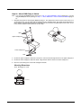
Step 1a – Attach RAM Ball to Vehicle ................................................................... 4-19
Step 1b – Mount RAM Clamp to Vehicle ............................................................... 4-20
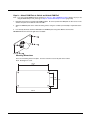
Step 1c – Attach RAM Plate to Vehicle and Attach RAM Ball ............................... 4-21
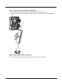
Step 2 – Attach RAM Mount Ball to the Thor VM1 Quick Mount Smart Dock ....... 4-22
Step 3 – Attach Thor VM1 Assembly to RAM Mount............................................. 4-23
Step 4 – Place the Thor VM1 into the Dock........................................................... 4-23
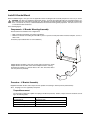
Install U Bracket Mount ..................................................................................................... 4-24
Components - U Bracket Mounting Assembly ............................................................. 4-24
Procedure - U Bracket Assembly................................................................................. 4-24
Torque Measurement ............................................................................................ 4-24
Mounting Positions ................................................................................................ 4-25
Step 1 - Install U Bracket to Vehicle ...................................................................... 4-25
Step 2 - Remove RAM Ball.................................................................................... 4-26
Step 3 - Attach Adapter Bracket ............................................................................ 4-26
iii
Connect Cables ................................................................................................................. 4-27
Strain Relief Cable Clamps.......................................................................................... 4-27
Connect Power ............................................................................................................ 4-28
Power Cable Cautions ................................................................................................. 4-28
12-48 VDC Vehicles (10-60 VDC Direct Connection)............................................ 4-29
60-144 VDC Vehicles (50-150 VDC Power Supply, Screws on Side of Lid) ......... 4-34
60-144 VDC Vehicles (50-150 VDC Power Supply, Screws on Top of Lid) .......... 4-38
VX6 / VX7 Adapter Cable ...................................................................................... 4-42
Thor VX8 / Thor VX9 Adapter Cable ..................................................................... 4-43
Screen Blanking..................................................................................................... 4-44
External AC/DC Power Supply .............................................................................. 4-47
Connect USB Host....................................................................................................... 4-47
Connect USB Client..................................................................................................... 4-48
Connect Serial Device ................................................................................................. 4-48
Connect a Tethered Scanner................................................................................. 4-48
Connect Headset Cable............................................................................................... 4-49
Adjust Headset / Microphone and Secure Cable................................................... 4-49
Connect CANbus Cable............................................................................................... 4-50
Install Remote Antenna ............................................................................................... 4-51
802.11 Remote Mount Antenna............................................................................. 4-51
WAN Remote Mount Antenna ............................................................................... 4-53
GPS Remote Mount Antenna ................................................................................ 4-53
Apply Touch Screen Protective Film ................................................................................. 4-54
Installation.................................................................................................................... 4-54
Removal....................................................................................................................... 4-54
Disconnect UPS Battery .................................................................................................... 4-55
Install SD Card .................................................................................................................. 4-56
Install SIM Card ................................................................................................................. 4-57
Replace Front Panel.......................................................................................................... 4-58
Replace UPS Battery......................................................................................................... 4-60
Chapter 5 - Software
Microsoft Windows Setup and Configuration....................................................................... 5-1
Drive C Folder Structure ................................................................................................ 5-1
Software Loaded on Drive C.................................................................................... 5-1
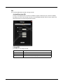
Control Panel....................................................................................................................... 5-3
About ............................................................................................................................. 5-3
Software................................................................................................................... 5-3
Versions................................................................................................................... 5-3
Network IP ............................................................................................................... 5-4
AutoOn........................................................................................................................... 5-5
Standard .................................................................................................................. 5-5
Ignition Control......................................................................................................... 5-5
Auto-On ................................................................................................................... 5-5
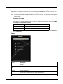
Bluetooth........................................................................................................................ 5-6
Bluetooth Devices.................................................................................................... 5-8
Discover................................................................................................................... 5-8
Settings.................................................................................................................. 5-10
iv
Reconnect.............................................................................................................. 5-12
About ..................................................................................................................... 5-13
Using Bluetooth ..................................................................................................... 5-14
Display ......................................................................................................................... 5-18
Power Options ............................................................................................................. 5-19
Select a Power Scheme ........................................................................................ 5-19
View UPS Battery Status ....................................................................................... 5-20
Hibernate ............................................................................................................... 5-22
Screen Control............................................................................................................. 5-23
Screen Blanking..................................................................................................... 5-24
Automatic Brightness Control ................................................................................ 5-24
Current Level ......................................................................................................... 5-24
Defroster Control ................................................................................................... 5-24
Screen Rotation ........................................................................................................... 5-25
Sounds......................................................................................................................... 5-25
System Rating (Windows Experience Index)............................................................... 5-26
Tablet PC Settings (Touch Screen Calibration)........................................................... 5-26
User Accounts ............................................................................................................. 5-26
Wi-Fi ............................................................................................................................ 5-26
Bar Code Readers............................................................................................................. 5-27
Scanner Wedge ........................................................................................................... 5-27
Touch Screen Calibration .................................................................................................. 5-27
BIOS .................................................................................................................................. 5-28
Accessing the BIOS Setup .......................................................................................... 5-28
Boot Order ................................................................................................................... 5-28
Exiting BIOS Setup ...................................................................................................... 5-28
Thor VM1 Recovery DVD .................................................................................................. 5-28
Upgrading the Thor VM1 ................................................................................................... 5-28
Automatic Firmware Update Utility .................................................................................... 5-29
Requirements .............................................................................................................. 5-29
Firmware Distribution Files .......................................................................................... 5-29
Update Process ........................................................................................................... 5-29
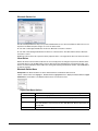
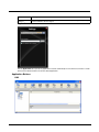
Configuration Cloning Utility (CCU) ................................................................................... 5-30
Configuration Cloning Utility GUI ................................................................................. 5-31
Menu Options ........................................................................................................ 5-32
Shortcuts................................................................................................................ 5-34
Modifying Settings ................................................................................................. 5-35
Using the CCU....................................................................................................... 5-36
Configuration Cloning Utility Command Line Interface ................................................ 5-37
Chapter 6 - Wireless Network Connections
Network Connections Control Panel.................................................................................... 6-1
Summit Wireless Network Configuration ............................................................................. 6-1
Important Notes ................................................................................................................... 6-1
Summit Client Utility ............................................................................................................ 6-1
Summit Tray Icon........................................................................................................... 6-1
Wireless Zero Config Utility ........................................................................................... 6-2
To Switch Control to the Wireless Zero Config Utility .............................................. 6-2
v
To Switch Control to SCU........................................................................................ 6-2
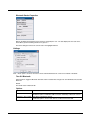
Main ............................................................................................................................... 6-3
Admin Login............................................................................................................. 6-3
Profile............................................................................................................................. 6-5
Buttons..................................................................................................................... 6-5
Profile Parameters ................................................................................................... 6-6
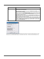
Status............................................................................................................................. 6-8
Diags.............................................................................................................................. 6-9
Global .......................................................................................................................... 6-10
Custom Parameter Option ..................................................................................... 6-11
Global Parameters................................................................................................. 6-11
Logon Options ....................................................................................................... 6-13
Sign-On vs. Stored Credentials ......................................................................................... 6-15
To Use Stored Credentials .......................................................................................... 6-15
To Use Sign On Screen............................................................................................... 6-16
To Use Windows Username and Password ................................................................ 6-16
Windows Certificate Store vs. Certs Path.......................................................................... 6-17
User Certificates .......................................................................................................... 6-17
Root CA Certificates .................................................................................................... 6-17
Certs Path.............................................................................................................. 6-17
Windows Certificate Store ..................................................................................... 6-17
Configuring the Profile ....................................................................................................... 6-18
No Security .................................................................................................................. 6-19
WEP............................................................................................................................. 6-20
LEAP............................................................................................................................ 6-21
PEAP/MSCHAP........................................................................................................... 6-22
PEAP/GTC................................................................................................................... 6-24
WPA/LEAP .................................................................................................................. 6-26
EAP-FAST ................................................................................................................... 6-27
EAP-TLS...................................................................................................................... 6-29
WPA PSK .................................................................................................................... 6-31
Certificates......................................................................................................................... 6-31
Generate a Root CA Certificate ................................................................................... 6-32
Install a Root CA Certificate......................................................................................... 6-33
Generate a User Certificate ......................................................................................... 6-34
Exporting a User Certificate................................................................................... 6-35
Install a User Certificate............................................................................................... 6-36
Manually Initiate Certificate Installation ................................................................. 6-37
OneClick Internet............................................................................................................... 6-38
Preparing for Initial Use on the Thor VM1 ................................................................... 6-38
Install SIM Card ..................................................................................................... 6-38
Load Firmware....................................................................................................... 6-38
Activation ............................................................................................................... 6-38
Using OneClick Internet............................................................................................... 6-40
Connection Management....................................................................................... 6-40
Menu Buttons............................................................................................................... 6-41
Radio Button .......................................................................................................... 6-41
Statistics Button ..................................................................................................... 6-41
vi
Update Button........................................................................................................ 6-41
Help Button ............................................................................................................ 6-41
Settings Button ...................................................................................................... 6-42
Application Buttons ...................................................................................................... 6-49
SMS ....................................................................................................................... 6-49
Web Browser ......................................................................................................... 6-52
Email...................................................................................................................... 6-52
GPS ....................................................................................................................... 6-52
About ........................................................................................................................... 6-53
System Requirements ........................................................................................... 6-53
OneClick Internet Connection Manager....................................................................... 6-55
Connection Management....................................................................................... 6-56
Information Buttons................................................................................................ 6-57
Chapter 7 - Key Maps
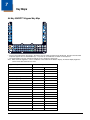
64-Key QWERTY Keypad Key Map .................................................................................... 7-1
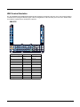
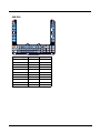
IBM Terminal Emulation ...................................................................................................... 7-5
IBM 3270 ....................................................................................................................... 7-5
IBM 5250 ....................................................................................................................... 7-6
Chapter 8 - Specifications and Reference Material
Technical Specifications ...................................................................................................... 8-1
Thor VM1 ....................................................................................................................... 8-1
Quick Mount Smart Dock............................................................................................... 8-1
Dimensions.......................................................................................................................... 8-2
Thor VM1 ....................................................................................................................... 8-2
Quick Mount Smart Dock............................................................................................... 8-2
Environmental Specifications .............................................................................................. 8-2
Thor VM1 and Quick Mount Smart Dock ....................................................................... 8-2
Network Card Specifications ............................................................................................... 8-3
Summit 802.11 a/b/g/n................................................................................................... 8-3
Bluetooth........................................................................................................................ 8-3
WWAN ........................................................................................................................... 8-3
Port and Connector Pinouts ................................................................................................ 8-4
Power Supply Connector ............................................................................................... 8-4
COM1 and COM2 Connector ........................................................................................ 8-4
USB Connector.............................................................................................................. 8-5
USB Y Cable............................................................................................................ 8-5
CANbus / Audio Connector............................................................................................ 8-6
Headset Adapter Cable ........................................................................................... 8-6
CANbus Y Cable...................................................................................................... 8-7
Hat Encoding ....................................................................................................................... 8-8
Chapter 9 - Customer Support
Product Service and Repair................................................................................................. 9-1
Technical Assistance........................................................................................................... 9-1
Limited Warranty ................................................................................................................. 9-1
vii
viii
1
Thor VM1 Agency Information
Thor VM1 mobile computers meet or exceed the requirements of all applicable standards organizations for safe operation.
However as with any electrical equipment, the best way to ensure safe operation is to operate them according to the agency
guidelines that follow. Read these guidelines before using your Thor VM1.
This documentation is relevant for the following Thor models: VM1W.
!
RISK OF EXPLOSION IF BATTERY IS REPLACED BY AN INCORRECT TYPE. The battery should be disposed of by
a qualified recycler or hazardous materials handler. Do not incinerate the battery or dispose of the battery with general
waste materials.
FCC Part 15 Statement
This device complies with FCC Rules, part 15. Operation is subject to the following two conditions:
1. This device may not cause harmful interference, and
2. This device must accept any interference received, including interference that may cause undesired operation.
NOTE - This equipment has been tested and found to comply with the limits for a Class A digital device, pursuant to Part 15 of
the FCC Rules. These limits are designed to provide reasonable protection against harmful interference when the equipment is
operated in a commercial environment. This equipment generates, uses, and can radiate radio frequency energy and, if not
installed and used in accordance with the instruction manual, may cause harmful interference to radio communications. Operation of this equipment in a residential area is likely to cause harmful interference in which case the user will be required to correct the interference at his own expense.
Caution - Changes or modifications made to this equipment not expressly approved by Honeywell may void the FCC authorization to operate this equipment.
FCC 5GHz Statement
LAN devices are restricted to indoor use only in the band 5150-5250 MHz.
For the band 5600-5650 MHz, no operation is permitted.
!
When using IEEE 802.11a wireless LAN, this product is restricted to indoor use, due to its operation in the 5.15- to 5.25GHz Frequency range. The FCC requires this product to be used indoors for the frequency range of 5.15 GHz to 5.25
GHz to reduce the potential for harmful interference to co-channel mobile satellite systems. High-power radar is allocated
as the primary user of the 5.25- to 5.35-GHz and 5.65- to 5.85-GHz bands. These radar stations can cause interference
with and/or damage to this device.
EMC Directive Requirements
This is a Class A product. In a domestic environment this product may cause radio interference in which case the user may be
required to take adequate measures.
Canada, Industry Canada (IC) Notices
This Class A digital apparatus complies with Canadian RSS-GEN issue 3:2010 and RSS-210 issue 8:2010.
Operation is subject to the following two conditions: (1) this device may not cause interference, and (2) this device must accept
any interference, including interference that may cause undesired operation of the device.
Radio Frequency (RF) Exposure Information
The radiated output power of the Honeywell Thor VM1 is below the Industry Canada (IC) radio frequency exposure limits. The
Honeywell Thor VM1 should be used in such a manner such that the potential for human contact during normal operation is
minimized.
This device has been certified for use in Canada. Status of the listing in the Industry Canada’s REL (Radio Equipment List) can
be found at the following web address: Additional Canadian information on RF exposure also can be found at the following web
address: Canada, avis d'Industry Canada (IC)
1-1
Cet appareil numérique de classe A est conforme aux normes canadiennes RSS-GEN numéro 3:2010 et RSS-210 numéro
8:2010.
Son fonctionnement est soumis aux deux conditions suivantes : (1) cet appareil ne doit pas causer d'interférence et (2) cet
appareil doit accepter toute interférence, notamment les interférences qui peuvent affecter son fonctionnement.
Informations concernant l'exposition aux fréquences radio (RF)
La puissance de sortie émise par de le Honeywell Thor VM1 est inférieure à la limite d'exposition aux fréquences radio d'Industry Canada (IC). Utilisez le Honeywell Thor VM1 de façon à minimiser les contacts humains lors du fonctionnement normal.
Ce périphérique est homologué pour l'utilisation au Canada. Pour consulter l'entrée correspondant à l’appareil dans la liste
d'équipement radio (REL - Radio Equipment List) d'Industry Canada rendez-vous sur: Pour des informations supplémentaires
concernant l'exposition aux RF au Canada rendez-vous sur : ANATEL (Brazil)
Este equipamento opera em caráter secundário, isto é, não tem direito a proteção contra interferência prejudicial, mesmo de
estações do mesmo tipo, e não causar interferência a sistema operando em caráter primário.
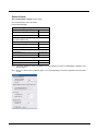
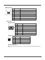
COFETEL
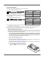
ANEXO CUMPLIMIENTO REGULATORIO NOM-121-SCT1-2009
EQUIPO: Terminal montada en vehículo
MARCA: Honeywell
MODELO: VM1 W
Para su uso en México, la operación de este equipo está sujeta a las siguientes dos condiciones: (1) es posible que este equipo
o dispositivo no cause interferencia perjudicial y (2) este equipo o dispositivo debe aceptar cualquier interferencia, incluyendo la
que pueda causar su operación no deseada.
Este equipo ha sido diseñado para operar con las antenas que enseguida se enlistan y para una ganancia máxima de antena
de 2.0 y 1.0 dBi @ 2.4 GHz WLAN; 4.0 y 5.0 dBi @ 5 GHz WLAN; -1.5 dBi @ 2.4 GHz para Bluetooth. Siendo únicas las antenas con que cuenta la terminal. El uso con este equipo de antenas no incluidas en esta lista o que tengan una ganancia mayor
que lo especificado quedan prohibidas. La impedancia requerida de la antena es de 50 ohms.1
Marca
Modelo
Tipo
Ganancia
LARSEN
R380500314
Dipolo, Banda Dual
2.0 y1.0 dBi @ 2.4 GHz WLAN
LARSEN
R380500314
Dipolo, Banda Dual
4.0 y 5.0 dBi @ 5 GHz WLAN
ANATEL (Brazil)
Este equipamento opera em caráter secundário, isto é, não tem direito a proteção contra interferência prejudicial, mesmo de
estações do mesmo tipo, e não causar interferência a sistema operando em caráter primário.
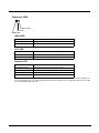
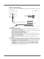
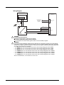
Vehicle Power Supply Connection Safety Statement
WARNING - For proper and safe installation, the input power cable must be connected to a fused circuit on the vehicle. If the
supply connection is made directly to the battery, the fuse should be installed in the positive lead within 5 inches of the battery’s
positive (+) terminal. The fused circuit requires a maximum time delay (slow blow) fuse with a current rating as noted below.
• For 12VDC input, use a 10A slow blow fuse that has a DC voltage rating greater than 12VDC.
• For 24VDC input, use a 6A slow blow fuse that has a DC voltage rating greater than 24VDC.
• For 36VDC input, use a 4A slow blow fuse that has a DC voltage rating greater than 36VDC.
• For 48VDC input, use a 3A slow blow fuse that has a DC voltage rating greater than 48VDC.
Note: For North America, a UL Listed fuse is to be used
Li-Ion Battery
When disposing of the Thor VM1 UPS battery, the following precautions should be observed: The battery should be disposed of
properly. The battery should not be disassembled or crushed. The battery should not be heated above 212°F (100°C) or incinerated.
1-2
Safety requirements restrict the temperature at which the Li-Ion UPS battery can be charged. Charging is disabled if the ambient temperature is outside of the 0ºC to 35ºC safe charging range. In order to maintain UPS charge the Thor VM1 should have
power applied while the unit is within the safe charging range for at least an hour each day.
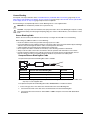
RF Safety Notice
This device is intended to transmit RF energy. For protection against RF exposure to humans and in accordance with
FCC rules and Industry Canada rules, this transmitter should be installed such that a minimum separation distance of at
least 20 cm (7.8 in.) is maintained between the antenna and the general population. This device can only be co-located
with FCC ID:TWG-SDCPE15N.
Bluetooth
Class II
Honeywell Scanning & Mobility Product Environmental Information
Refer to www.honeywellaidc.com/environmental for the RoHS / REACH / WEEE information.
CE Mark
The CE marking on the product indicates that this device is in conformity with the following directives:
• 1995/5/EC R&TTE
• 2011/65/EU RoHS (Recast)
In addition, complies to 2006/95/EC Low Voltage Directive, when shipped with recommended power supply.
European contact:
Hand Held Products Europe BV
Nijverheidsweg 9-13
5627 BT Eindhoven
The Netherlands
Honeywell shall not be liable for use of our product with equipment (i.e., power supplies, personal computers, etc.) that is not CE
marked and does not comply with the Low Voltage Directive.
Part
Number
1177
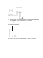
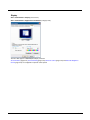
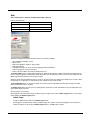
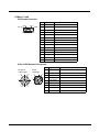
Dealer License - Republic of Singapore
Republic of Singapore - Dealer License Number DA104647 complies with IDA Standards.
Complies with
IDA Standards
DA104647
WWAN is not available in Singapore.
1-3
1-4
2
Getting Started
Overview
The Thor VM1 Vehicle Mount Computer (VMC) is a rugged, vehicle mounted computer running a Microsoft® Windows® Embedded Standard 2009 operating system and capable of wireless data communications from a fork-lift truck or any properly configured vehicle. Wireless communications are supported over a 802.11 WLAN network and, optionally, over a WWAN network.
The Bluetooth® module supports Bluetooth printers and scanners.
!
CAUTION - Before shipping the Thor VM1, be sure to Disconnect UPS Battery (page 4-55) .
The Thor VM1 is designed for use with a vehicle Quick Mount Smart Dock. The dock installs in the vehicle and connects to
vehicle power. The dock provides conditioned input power for the Thor VM1. Peripheral connections are on the dock. The Thor
VM1 is designed to easily be removed from the dock with a latch on the lower rear of the Thor VM1 housing. Since the dock
remains attached to the vehicle, the Thor VM1 computer can easily be moved from one vehicle equipped with a dock to another
vehicle equipped with a dock.
The Thor VM1 contains a UPS battery which, when fully charged, can power the Thor VM1 for a minimum of 30 minutes. This
can be when the Thor VM1 is not attached to a Quick Mount Smart Dock or when the Thor VM1 is attached to a dock but the
vehicle power is interrupted, such as when the vehicle battery is being changed.
Contact Technical Assistance (page 9-1) for information on the latest upgrades for your Thor VM1.
THOR
SYS
VM1
UPS
Wi Fi
SSD
About this Guide
This user’s guide has been developed for a Thor VM1 with a Microsoft® Windows® Embedded Standard 2009 operating system.
Out of the Box
The following items may be packaged separately:
• Thor VM1
• Quick Mount Smart Dock (includes 10-60VDC power cable)
• RAM or U-Bracket vehicle mount kit
2-1
If you ordered additional accessories for the Thor VM1, verify they are also included with the order. Keep the original packaging
material in the event the Thor VM1 should need to be returned for service. For details, see Product Service and Repair (page 91).
Initial Setup for Thor VM1
This page lists a quick outline of the steps you might take when setting up a new Thor VM1. More instruction for each step is
listed later in this guide.
Contact Technical Assistance (page 9-1) if you need additional help.
Hardware Setup
1. Install RAM Mount (page 4-18) or Install U Bracket Mount (page 4-24) to the vehicle.
2. Place Thor VM1 in the Dock (page 4-16).
3. Connect Cables (page 4-27) for any peripherals.
4. Connect Power (page 4-28).
5. Secure all cables in Strain Relief Cable Clamps (page 4-27).
6. Press the Power Switch (page 3-5) on the dock to the on position.
7. Press the Power Button (page 3-5) on the Thor VM1.
Software
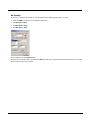
Languages
The Thor VM1 may be shipped with an English only operating system. Contact Technical Assistance (page 9-1) to
order a Thor VM1 Recovery DVD (page 5-27) in a different language. The language installed is identified on the Software tab of the About (see page 5-3) control panel.
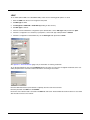
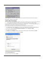
First Boot
When a new Thor VM1 starts up a EULA (End User License Agreement) may be displayed on the touch screen. It
remains on the screen until the Accept or Decline button is tapped with a stylus.
Tap the Accept button to accept the EULA terms and the Thor VM1 continues the startup process. The EULA is not
presented to the user again.
Tap the Decline button to decline the EULA and the Thor VM1 reboots. It will continue to reboot until the Accept button is tapped with the stylus.
Software Setup
Hardware setup should be completed before starting software setup.
1. If prompted, perform Touch Screen Calibration (page 5-26).
2.
Select a Power Scheme (page 5-18) and set timers.
3. Adjust Speaker Volume (page 2-5).
4. Pair Bluetooth (page 5-6) devices
5. Set Wireless client parameters using the Summit Client Utility (page 6-1).
6. Set terminal emulation parameters.
Quick Mount Smart Dock
The Thor VM1 assembly consists of two parts, the Thor VM1 computer and the Quick Mount Smart Dock.
The Thor VM1 contains an internal UPS battery that, once fully charged, powers the Thor VM1 for a minimum of 30 minutes
when the unit is not mounted in the dock.
The dock provides:
2-2
• A mount for the Thor VM1 computer. The dock attaches to a vehicle via a RAM or U-bracket mount or to a RAM table stand
for use in an office environment.
• Conditioned power for the Thor VM1. The dock accepts 10-60VDC power input directly or 50-150VDC power input with a DC/
DC converter.
• COM1 and COM2 serial connections for a tethered scanner, printer, PC connection, etc.
• USB host connection via an adapter cable.
• CANbus connection via an adapter cable.
• Headset connection via an adapter cable. When a headset is not attached, the microphone and speakers on the Thor VM1
are active.
• Strain relief cable mounts.
• Mobility of the Thor VM1, since the dock remains attached to the vehicle the Thor VM1 computer can easily be moved from
one vehicle equipped with a dock to another.
External antenna connectors may be present on the back of the Thor VM1. The connectors may include:
• 802.11 antenna connectors, used when the Thor VM1 is not equipped with internal antennas.
• External GPS antenna connector, when the Thor VM1 is equipped with GPS.
• External WWAN antenna connectors, when the Thor VM1 is equipped with WWAN. Optional WWAN radio (available in North
America, Europe, New Zealand, and Australia only).
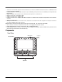
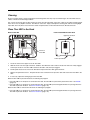
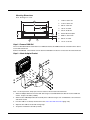
Components
Front View
Microphone
Ambient
Light
Sensor
Power Button
SYS
Wi Fi
UPS
SSD
Speakers
2-3
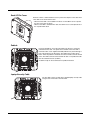
Back View with Quick Mount Smart Dock
Antenna Connectors
Strain Relief
Clamps
RAM Ball
SIM Card
Access Panel
SD Card
Access
Panel
Fuse
COM1 Connector
Power
Connector
COM2 Connector
USB Connector
Power
Switch
Provision for
Laptop Security
Cable
CANbus/Audio
Connector
Provision for Padlock
Quick Release Handle
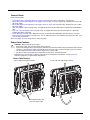
Access Panels
SD Card Access Panel with door removed
SIM Card Access Panel with door removed
CompactFlash
Hard Drive
SIM Card Slot
for WWAN Radio
SD (Secure Digital)
Memory Card Slot
UPS Battery
Disconnect
SSD
Access Panel Door is labeled with
2-4
and
SD
Access Panel Door is labeled with
.
SIM
.
Backlights and Indicators
Display Backlight
There are several configuration options for the Thor VM1 display backlight:
Power Management
The display backlight is controlled by power management. When the user activity timer expires, the display backlight is
turned off. Timeouts can be set for the available power management schemes.
See Power Options (page 5-18) for configuration options.
Backlight Brightness
The intensity of the display backlight can be manually configured:
• Use the 2nd + F7 keppress to increase backlight brightness or the 2nd + F8 keypress to decrease backlight
brightness.
Refer to the Screen Control (page 5-22) panel for the current display brightness level.
Screen Blanking
The Thor VM1 can be configured to blank (blackout) the display while the vehicle is in motion.
Refer to the Screen Control (page 5-22) panel for information.
Keypad Backlight
The integrated keypad backlight follows the display backlight. If the display backlight is on, the keypad backlight is on.
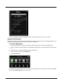
Speaker Volume
The speaker volume can be adjusted via the Thor VM1 keypad:
• Use the 2nd + F9 keppress to increase speaker volume or the 2nd + F10 keypress to decrease speaker volume.
The current volume level can be viewed on the Sounds (page 5-24) control panel or via the system tray speaker icon.
These items can also be used to adjust speaker volume
2-5
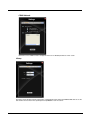
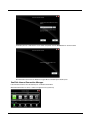
Power Up
!
If a USB drive, such as a thumb drive is attached to the Thor VM1, the device attempts to boot from the USB drive and
cannot. Please remove the USB drive and power up the Thor VM1 again.
The Quick Mount Smart Dock has a power switch on the back.
The “On” side of this rocker switch has a raised bump to allow the state of the switch to be determined when the switch may not
be easily viewed, for example, after the dock is mounted in a vehicle.
After external power has been connected and the Thor VM1 has been mounted in the dock, press the side of the power switch
with the raised bump to pass power from the dock to the Thor VM1.
Next locate the power button on the front of the Thor VM1.
Press the power button to turn the Thor VM1 on. When the Windows desktop is displayed or an application begins, the power up
sequence is complete.
See Power Controls (see page 3-5) for more information.
2-6
Rebooting the Thor VM1
!
If a USB drive, such as a thumb drive is attached to the Thor VM1, the device attempts to boot from the USB drive:
• If the USB drive contains a bootable sector, the Thor VM1 boots from the USB drive.
• If the USB drive does not contain a bootable sector, the Thor VM1 does not boot. Remove the USB drive and boot
the Thor VM1 again.
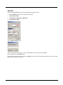
Restart
Restart performs a controlled shutdown of the Thor VM1 and then restarts the device.
• Use the Ctrl + Alt + Del keypress sequence to start the task manager. Tap the Shut Down button and select
Restart from the pull-down list. Tap the OK button to restart the Thor VM1..
• Select Start > Shut Down > Restart and tap OK to restart the Thor VM1
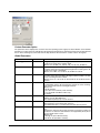
Tapping the Touch Screen with a Stylus
Note: Always use the point of the stylus for tapping or making strokes on the touch screen.
Never use an actual pen, pencil, or sharp/abrasive object to write on the touch screen.
Hold the stylus as if it were a pen or pencil. Touch an element on the screen with the tip of the stylus then remove the stylus from
the screen.
Firmly press the stylus into the stylus holder when the stylus is not in use.
Using a stylus is similar to moving the mouse pointer then left-clicking icons on a desktop computer screen.
Using the stylus to tap icons on the touch screen is the basic action that can:
•
•
•
•
•
•
•
Open applications
Choose menu commands
Select options in dialog boxes or drop-down boxes
Drag the slider in a scroll bar
Select text by dragging the stylus across the text
Place the cursor in a text box prior to typing in data
Place the cursor in a text box prior to retrieving data using a scanner/imager.
A right click is generated by tapping the mouse icon , usually located in the upper right hand corner of the screen. After
tapping, the mouse icon highlights the right button. The next touch screen tap is treated as a right click. The mouse icon
returns to the left button highlighted so subsequent taps are treated as left clicks.
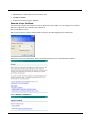
Note: If the mouse icon is not displayed, this feature can be enabled by tapping the PenMount icon
in the System Tray. From
the menu that pops up, tap the Right Button to enable the mouse icon. When this option is enabled, a checkmark is
displayed in the menu.
A stylus replacement kit is available.
When a dialog box is too large for the display, tap and drag the dialog box up or down or from side to side to view the remainder
of the dialog box.
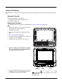
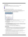
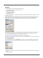
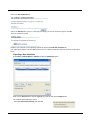
Setup Terminal Emulation Parameters
Note: The instructions below are for Honeywell RFTerm. If a different terminal emulation software is installed on your Thor VM1
refer to the documentation for that software.
Before you make a host connection, you will, at a minimum, need to know:
• the alias name or IP address (Host Address) and
• the port number (Telnet Port) of the host system to properly set up your host session.
1. Make sure the mobile client network settings are configured and functional. If you are connecting over wireless LAN
(802.11x), make sure your mobile client is communicating with the Access Point.
2. From Start > Program, run RFTerm or tap the RFTerm icon on the desktop.
3. Select Session > Configure from the application menu and select the “host type” that you require. This will depend on the
type of host system that you are going to connect to; i.e., 3270 mainframe, AS/400 5250 server or VT host.
2-7
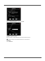
4. Enter the “Host Address” of the host system that you wish to connect to. This may either be a DNS name or an IP address
of the host system.
5. Update the telnet port number, if your host application is configured to listen on a specific port. If not, just use the default
telnet port.
6. Select OK.
7. Select Session > Connect from the application menu or tap the “Connect” button on the Tool Bar. Upon a successful
connection, you should see the host application screen displayed.
To change options such as Display, Colors, Cursor, Bar Code, etc., refer to these sections in the RFTerm Reference Guide for
complete descriptions of these and other features.
Cleaning the Touch Screen
Note: These instructions are for components made of glass. If there is a removable protective film sheet on the display, remove
the film sheet before cleaning the screen.
Keep fingers and rough or sharp objects away from the bar code reader scanning aperture and the mobile device touch screen.
If the glass becomes soiled or smudged, clean only with a standard household cleaner such as Windex® without vinegar or use
isopropyl alcohol. Dampen the cloth with the cleaner and then wipe the surface.
Do not use paper towels or harsh-chemical-based cleaning fluids since they may result in damage to the glass surface. Use a
clean, damp, lint-free cloth.
Do not scrub optical surfaces. If possible, clean only those areas which are soiled. Lint and particulates can be removed with
clean, filtered canned air.
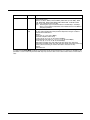
Startup Help
Contact Technical Assistance (page 9-1) if you need more help.
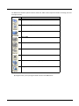
Touch screen is not accepting stylus Press Ctrl+Esc to force the Start Menu to appear. Use the tab, backtab and arrow keys
taps or needs recalibration.
to move the cursor from element to element.
See Touch Screen Calibration (page 5-26).
Thor VM1 seems to lockup as soon There may be slight delays while the wireless client connects to the network, authorizaas it is rebooted.
tion for voice-enabled applications complete, and Bluetooth relationships establish or reestablish.
When an application begins, the Thor VM1 is ready for use.
2-8
3
Hardware Overview
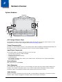
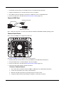
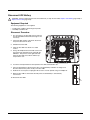
System Hardware
Antenna Connectors
CompactFlash
Hard Drive
SIM
Card
CF Slot
SIM Slot
SD Slot
Secure
Digital
Memory
Card
Serial
Connector
COM1
Serial
Connector
COM2
USB
Connector
CANbus/
Audio
Connector
Power
Connector
802.11a/b/g/n Wireless Client
The Thor VM1 has an 802.11a/b/g/n network card that supports diversity with two internal or external antennas. Power
management for the network card is configured with the Summit Client Utility (page 6-1).
Central Processing Unit
The CPU is a 1.6 GHz Intel Atom processor. The operating system is Microsoft Windows Embedded Standard 2009. The
OS image is stored on an internal CompactFlash memory card and is loaded into DRAM for execution.
Input/Output Components
The Thor VM1 supports the following I/O components of the core logic:
•
•
•
•
•
Two 9-pin RS-232 serial ports, COM1 and COM2.
One slot for SD memory card.
CompactFlash (CF) memory card drive.
Integrated keyboard.
Ports available via adapter cables: USB host port, CANbus, Audio. USB client port is not supported with Windows
Embedded Standard 2009.
System Memory
Main system memory is 2 GB SDRAM.
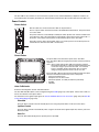
Video Subsystem
The Thor VM1 video subsystem consists of a color TFT display. The video subsystem complies with the VESA VL bus
standard. The resolution of this display is pixels. This resolution complies with the VGA graphics industry standard.
The display supports screen blanking to eliminate driver distraction when the vehicle is in motion.
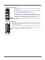
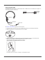
Audio Interface
Speakers are located on the bottom front of the Thor VM1. A headset adapter cable provides a connection for headset
operation. When a headset is plugged into the adapter cable, the main speakers are disabled.
3-1
A microphone is located at the upper right of the Thor VM1 display, near the Thor VM1 emblem. When a headset is
plugged into the adapter cable, the internal microphone is disabled.
Card Slots
CompactFlash (CF) Slot
The CF ATA slot is not hot swappable. The Thor VM1 must be powered down to insert or remove an ATA card. Since
the operating system is stored on the CF ATA card, the Thor VM1 cannot operate without the ATA card.
Secure Digital (SD) Slot
The SD slot accepts an SD memory card. The SD card is hot swappable.
Bluetooth EZPair
The Thor VM1 contains Bluetooth version 2.0 with Enhanced Data Rate (EDR) up to 3.0 Mbit/s over the air. Bluetooth
device connection (or pairing) can occur at distances up to 32.8 ft (10 meters) Line of Sight. The wireless client retains
wireless connectivity while Bluetooth is active.
The user cannot select PIN authentication or encryption on connections from the Thor VM1. However, the Thor VM1 supports authentication requests from pairing devices. If a pairing device requests authentication or encryption, the Thor VM1
displays a prompt for the PIN or passcode. Maximum encryption is 128 bit. Encryption is based on the length of the user’s
passcode.
Bluetooth simultaneously supports one printer as a slave Bluetooth device and one scanner, either as a slave or as a master Bluetooth device.
• The LED on the Bluetooth scanner illuminates during a scanning operation.
• Bar code data captured by the Bluetooth scanner can be manipulated by the settings in the optional Freefloat Link*One
application.
• Multiple beeps may be heard during a bar code scan using a mobile Bluetooth scanner; beeps from the mobile Bluetooth
scanner as the bar code data is accepted/rejected, and other beeps from the Thor VM1 during final bar code data
manipulation.
WWAN
WWAN (Wireless Wide Area Networking) is available on the Thor VM1. A slot is provided for a SIM card.
GPS
GPS (Global Positioning System) is available on the Thor VM1.
Power
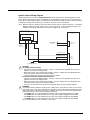
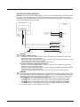
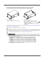
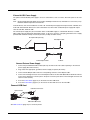
Vehicle DC Power Supply
Vehicle power input for the Thor VM1 dock is 10V to 60V DC and is accepted without the need to perform any manual operation within the Thor VM1 dock, see 12-48 VDC Vehicles (10-60 VDC Direct Connection) (page 4-29). The dock provides
a conditioned power output for the Thor VM1. By using a specified DC/DC power supply, input voltage of 50-150V DC can
be accepted, see 60-144 VDC Vehicles (50-150 VDC Power Supply, Screws on Top of Lid) (page 4-38) or 60-144 VDC
Vehicles (50-150 VDC Power Supply, Screws on Top of Lid) (page 4-38).
Power input is fused for protection and the fuse is externally accessible, see Fuse (page 3-4).
External AC Power Supply
If DC power is not available – for example, in an office environment – an optional external Universal Input Power Supply can
be used to convert AC wall power to an appropriate DC level. AC to DC power input for the Thor VM1 is delivered to the
Quick Mount Smart Dock via an optional external power supply and adapter cable. See External AC/DC Power Supply
3-2
(page 4-47).
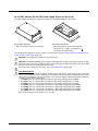
Uninterruptible Power Supply
The Thor VM1 contains an internal UPS battery. The user can Replace UPS Battery (page 4-60).
The UPS battery is automatically charged when the Thor VM1 is placed in a powered dock, provided the safe charging temperature conditions below are met.
When external power is removed, the UPS automatically powers the Thor VM1 with no user intervention. When running on
UPS power, the power management timeouts may be different than when vehicle power is applied.
The UPS allows the Thor VM1 to continue operation when not mounted in a dock or when the vehicle battery is being
swapped. When fully charged the UPS battery is designed to power the Thor VM1 for a minimum of 30 minutes at temperatures of -20ºC (-4ºF) or greater. For the extended temperature version of the Thor VM1, the UPS provides a minimum
of 10 minutes of operation between -20ºC (-4ºF) and -30ºC (-22ºF).
If operating on UPS power and the UPS battery becomes critically low, the Thor VM1 performs a controlled shutdown.
If there is no external power available, there must be 10% or greater power in the UPS battery or the Thor VM1 does not
power on.
The UPS status LED and the Battery Control Panel can be used to monitor the state of the UPS battery.
Safe Charging Temperature Range
The internal temperature of the Thor VM1 is the trigger for UPS battery charging.
• The UPS battery is not charged when the internal Thor VM1 temperature is below 0°C (32°F). This corresponds to
an ambient (room) temperature of approximately -10°C (-14°F).
• The UPS battery is not charged when the internal Thor VM1 temperature is above 45°C (113°F). This corresponds
to an ambient (room) temperature of approximately 35°C (95°F).
• If the UPS battery cannot be charged due to a temperature extreme, the UPS Status LED (page 3-11) is amber.
Move the Thor VM1 to a different location to charge the UPS battery.
When the Thor VM1 is operated in an environment where the UPS battery is not able to charge due to temperature
extremes, the Thor VM1 should be removed to a location within the safe charging temperature range during off hours.
A discharged UPS battery cannot protect against data loss in the event vehicle power is interrupted.
Charging Timeout
• A fully discharged UPS battery normally recharges in less than 4 hours when the Thor VM1 is in a powered dock and
within the safe charging temperature range.
• If the UPS battery is not charged before an 8 hour (or 4 hours for some earlier software revisions) timeout period
expires, the UPS Status LED (page 3-11) is amber.
• The charge timeout is reset if charging resumes upon application of external power.
• The charge timeout is reset if charging resumes when the Thor VM1 enters the permissible temperature range for
charging.
Charging and Power Management
• Charging of the UPS battery continues when the Thor VM1 is in power management (display off, suspend or
hibernate modes).
Backup Battery
The Thor VM1 has a permanent Lithium battery installed to maintain time, date and CMOS setup information for a minimum
of 90 days. The lithium battery is not user serviceable and should last five years with normal use before it requires replacement.
Note: The backup battery should only be changed by authorized service personnel.
3-3
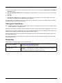
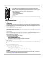
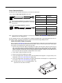
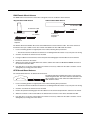
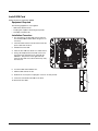
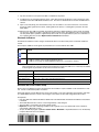
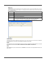
Fuse
The Thor VM1 uses an 8A time delay (slow blow), fuse that is externally accessible and user
replaceable. The fuse is located on the back of the Quick Mount Smart Dock. The fuse is accessed
by unscrewing the cap as indicated.
Should it need replacement, replace with same size, rating and type of fuse:
• Littelfuse 0215008.MXP
• Cooper Bussmann BK1/S506-8-R
• Bel Fuse 5HT 8-R
or equivalent.
Fuse has voltage on it even when power is off. Always disconnect input power before changing the
fuse.
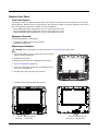
Power Management Modes
The Thor VM1 has four power modes: Full On, Standby, Hibernate and Off.
Full On Mode
When the Thor VM1 is attached to either vehicle power or an external power supply or is operating from the UPS battery and the power button is pressed, the Thor VM1 is in the On mode. In this mode, the keypad, touch screen and any
attached peripherals such as a scanner function normally. The display remains on until the display, standby or hibernate timer (if enabled) expires.
When in Full On mode, the status LED is solid green.
If the Thor VM1 is Full On, a press of the power button can be configured to put the unit in Standby. See the Advanced
(page 5-20) tab of the Power control panel.
StandbyMode
When the standby timer expires without a primary event occurring, the Thor VM1 transitions to Standby mode. Pressing the Power button exits Standby mode and transitions the Thor VM1 to Full On.
When in Standby mode, the status LED:
• blinks green very slowly if external power is attached.
• is off if external power is not attached.
System Standby Wakeup Events
The following event transitions the Thor VM1 from Standby to Full On Mode:
• Pressing and releasing the Power button
Hibernate Mode
When the Thor VM1 enters hibernate mode, all LEDs are off. Pressing the Power button returns the Thor VM1 to Full
On.
When in Hibernate Mode, the status LED:
• blinks green very slowly if external power is attached.
• is off if external power is not attached.
System Hibernate Wakeup Events
The following event transitions the Thor VM1 from Hibernate to Full On Mode:
• Pressing and releasing the Power button.
Off Mode
By default, the Thor VM1 turns off if the user presses the power button when the Thor VM1 is On. This behavior can
be configured on the Advanced (page 5-20) tab of the Power control panel.
3-4
The Thor VM1 is also off when it is not connected to a power source and the UPS battery is depleted. However, an
internal Real Time Clock (RTC) powered by an internal battery maintains the date and time while the Thor VM1 is off.
Power Controls
Power Switch
After all cables are connected, the Thor VM1 can be powered on.
There is a power switch located on the back of the Quick Mount Smart Dock. The power switch
is a rocker switch.
The power switch has a raised bump to identify the switch position even when it is hidden from
view. When the side of the switch with the raised bump is pressed, the power switch is On. If
the dock is connected to external power, the dock delivers power to the Thor VM1.
Generally, once the dock is powered On, there is no need to power it off. The dock power can
remain On even when the Thor VM1 is not attached.
Power Button
The power button is located at the top left of the Thor VM1.
If the Thor VM1 is Off, pressing the power button starts the power up
sequence.
Note: This assumes that the Thor VM1 is docked in a powered
Quick Mount Smart Dock or that the internal UPS battery has
a sufficient charge to power the Thor VM1. If no external
power is available and the UPS battery does not have a
charge, pressing the power button causes no action.
If the Thor VM1 is On, pressing the power button performs the option
selected in the Advanced tab of the Power control panel:
• Ignore power button press
• Prompt the user to select action
• Shut down (default, an orderly shutdown is performed)
• Standby
• Hibernate
Auto On Behavior
Select the desired Ignition Control / Auto On behavior.
The Thor VM1 Auto On options can be configured using the AutoOn (page 5-5) control panel. Please refer to that section for more details on the options below.
For information on the Ignition input signal see Vehicle 10-60VDC Direct Power Connection (page 4-29) and Auto-On
Control Wiring Diagram (page 4-32).
Standard
The Thor VM1 is turned on and off manually by the user using the power button on the front of the device.
Ignition Control
The Thor VM1 is turned on automatically when a signal is received via the Ignition Input wire, which is part of the
DC Power Cable.
Auto-On
The Thor VM1 automatically powers up when power is provided.
3-5
External Connectors
Power the Thor VM1 off before attaching a cable to any port (serial, USB, Audio/CAN, etc.).
The external I/O connectors for the Thor VM1 are located on the right side of the Quick Mount Smart Dock (when viewed from
the back).
The Power Supply Connector (page 3-7) is on the left side of the dock (when viewed from the back).
Antenna connectors are located on the top rear of the Thor VM1.
Serial Connector (COM1 and COM2)
The COM1 and COM2 connectors are D-9 male connectors located on the back of the Quick
Mount Smart Dock.
Power the Thor VM1 off before attaching a cable to any port (serial, USB, Audio/CAN, etc.).
The serial connectors are industry-standard RS-232, PC/AT standard 9–pin “D” male connector. See COM1 and COM2 Connector (page 8-4) for connector pinout detail.
Pin 9 is configured to provide +5V for an external bar code scanner.
See Connect Serial Device (page 4-48) for more information.
If a COM port is not being used for a scanner, it can be used for Screen Blanking (page 444) when the vehicle is in motion.
Screen Blanking
The screen blanking signal can be provided either by a Honeywell Screen Blanking Box or a user supplied switch or
relay. See Screen Blanking (page 4-44) for information on connecting screen blanking accessories.
USB Connector
The USB connector is a D-9 female connector located on the back of the Quick Mount Smart
Dock. See USB Connector (page 10-5) for connector pinout detail.
Power the Thor VM1 off before attaching a cable to any port (serial, USB, Audio/CAN, etc.).
The USB client port is not supported with Windows Embedded Standard 2009 operating systems.
See Connect USB Host (page 4-33) for more information.
3-6
CANbus / Audio Connector
The CANbus/Audio connector is a D-15 male connector located on the back of the Quick
Mount Smart Dock.
The connector supports a headset adapter cable or a CANbus cable. The Thor VM1 does
not support connecting audio and CANbus simultaneously.
See CANbus / Audio Connector (page 8-6) for connector pinout detail.
A headset cable attaches to the CANbus / Audio connector and provides a quick connect
connection for a headset. See Connect Headset Cable (page 4-49) for more information.
The CANbus Y cable has a 9 pin F SAE J1939 (Deutsch) and 9 pin M SAE J1939 (Deutsch)
connector. See Connect CANbus Cable (page 4-50) for more information.
The CANbus interface is a virtual COM port. This port can be accessed using standard Windows API calls.
Power Supply Connector
Power is supplied to the Thor VM1 through the power connector. Additionally this assembly provides a connection point for the vehicle’s chassis ground to be connected internally to the conductive chassis of the computer.
The Thor VM1 internal power supply can accept DC input voltages in the range of 10 to 60 Volts
DC.
See Power Supply Connector (page 8-4) for connector pinout detail. See Connect Power (page 428) for more information on connecting power to the Thor VM1.
3-7
Antenna Connections
1
2
3
4
The Thor VM1 is equipped with an 802.11 radio and can be ordered with
internal antennas or external remote mount antennas. When the Thor
VM1 is ordered with internal antennas, the external antenna connectors
are not used. GPS and WWAN are optional on the Thor VM1 and require
external remote mount antennas.
1. WI-FI (MAIN) (Red label) 802.11 Main External Antenna Connector
2. WI-FI (AUX) (Yellow label) 802.11 Auxiliary External Antenna
Connector
3. GPS (Green label) GPS Antenna Connector
4. MOBILE NET (Blue label) WWAN Antenna Connector
External Antenna Connector
When the Thor VM1 is ordered with the internal antenna option, the 802.11 antenna connectors on
the back are not connected to the 802.11 radio. Instead the internal antenna connector is connected
to the 802.11 radio.
Remove the rubber cap, if present, from the antenna connector before connecting an external
antenna.
Internal 802.11 Antenna
If the internal 802.11 antenna option is ordered, antennas are mounted inside the Thor VM1. The internal antennas
are not user accessible.
Vehicle Remote Antenna
The external antennas can be remotely mounted on the vehicle. See Install Remote Antenna (page 4-51) for instructions. External antenna kits are available for the 802.11 Wi-Fi radio, GPS and WWAN.
3-8
Keyboard Options
The 2nd, ALT, CTRL and Shift keys (when present) are sticky keys. The Keyboard LEDs (page 3-13) identify the active sticky
modifier mode state of the keyboard.The Thor VM1 has an integrated keypad with five programmable keys and an available
external keyboard.
64-Key QWERTY Keyboard
SYS
UPS
SSD
The Thor VM1 has a QWERTY keyboard, available with a standard overlay, an IBM 3270 overlay or an IBM 5250 overlay.
• Because the keyboard only has 64 keys, all functions are not visible (or printed on the keyboard). Therefore the Thor
VM1 keyboard supports what is called hidden keys -- keys that are accessible but not visible on the keyboard.
• The keyboard does not have a NumLock indicator or key. NumLock is always On.
The Thor VM1 keyboard keys are backlit.
• By default, the keyboard backlight follows the display backlight. When the display backlight is on, the keyboard backlight
is on.
• If the display backlight brightness is increased (or decreased) the keyboard backlight brightness is increased (or
decreased).
• The keyboard backlight and the display share the same timer, which is configured in the Power Options (page 5-18)
control panel.
IBM 3270 Overlay
SYS
UPS
SSD
3-9
IBM 5250 Overlay
SYS
UPS
SSD
Keypad LEDs
See Keyboard LEDs (page 3-13) for details.
USB Keyboard / Mouse
A standard USB keyboard or mouse can be attached to the Thor VM1 using the appropriate adapter cable.
The Y cable attaches to the Thor VM1 and provides a USB connector. Please refer to documentation provided with the
USB keyboard or mouse for more information on their operation.
LED Functions
System LEDs
Connection LEDs
SYS
UPS
WiFi
SSD
2nd LED
Shift/CapsLock LED
Shift/CapsLock LED
Ctrl LED Alt LED
System LEDs
SYS (System Status) LED
SYS
UPS (Uninterruptible Power Supply) LED
SSD (Solid State Drive) LED
3 - 10
UPS
SS D
SYS (System Status) LED
LED Behavior
System State
Solid Green
• On
• On but Display Off
Green blinking very slowly
External power present
(1/2 sec. on, 4 1/2 sec. off)
• Standby
Off
External power present
• Hibernate
• Off
Off
External power not present
• Hibernate
• Standby
• Off
Green blinking slowly
External power present
(1/2 sec. on, 1 1/2 sec. off)
CPU temperature less than -20ºC, Heater warming CPU for 30 sec.
Green blinking slowly
External power not present
(1/2 sec. on, 1 1/2 sec. off)
CPU temperature less than -20ºC, Need to move unit to warmer environment
UPS Status LED
The behavior of the UPS LED depends if external power is connected or not.
External Power Present
LED Behavior
Off
Status
• No UPS charging
• UPS charged
Solid Green
UPS charging
Solid Amber
• Any charging fault
• Out of Safe Charging Temperature Range (page 3-3) Charging only occurs between
approximately -10°C and 35°C ambient temperature.
• No UPS present
• Charging Timeout (page 3-3) Not fully charged after 4 or 8 hours depending on
software revision.
External Power Not Present
LED Behavior
Off
Status
• Unit off
• UPS not present
Solid Amber
UPS supplying power and discharging
Solid Red
Approximately 2 minutes runtime until shutdown
SSD (Solid State Drive) LED
LED Behavior
Status
Flashing Green
SSD read or write activity
Off
No SSD read or write activity
3 - 11
Connection LEDs
Wi Fi
Bluetooth LED
Wi-Fi LED
WWAN LED
WWAN LED
LED Behavior
Status
Solid Green
Indicates a WWAN connection to a network
Off
Indicates no WWAN connection
Wi-Fi LED
LED Behavior
Status
Solid Green
Indicates a connection with an IP address to an Access Point
Off
Indicates no connection to an Access Point
Bluetooth LED
LED Behavior
Blue Blinking Slowly
Status
Bluetooth is paired but not connected to a device
Blue Blinking Medium
Bluetooth is paired and connected to a device
Blue Blinking Fast
Bluetooth is discovering Bluetooth devices
Off
Bluetooth hardware has been turned off
The Bluetooth LED blinks once every 6 seconds when the Bluetooth client is paired but not connected. It blinks once
for a very short time every 2 seconds when paired and connected. It blinks every second when in discovery. The LED
is off when the Bluetooth client is off.
3 - 12
Keyboard LEDs
The keyboard LEDs are located near the specified key.
2nd LED
LED Behavior
Solid Green
Off
Status
• Indicates the 2nd modifier key is active. 2nd mode is invoked for the next keypress only.
• Pressing the 2nd key a second time exits this modifier mode and turns off the LED.
2nd mode is not invoked.
Shift LEDs
There is one LED next to each Shift key. Both LEDs indicate the status of Shift mode and Caps Lock mode.
LED Behavior
Status
Blinking Green
• Indicates the keypad is in Shift mode. Shift mode is invoked for one keypress.
• Pressing the Shift key places the system in Shift mode.
• To exit Shift mode, press the Shift key again.
Solid Green
• When solid Green, indicates the keypad is in Caps Lock mode. Caps Lock mode is
invoked until canceled.
• Pressing the 2nd key followed by the Shift key places the system in Caps Lock mode.
• To exit Caps Lock mode, press 2nd + Shift again.
Off
Neither Shift or Caps Lock mode is invoked.
Ctrl LED
The Ctrl key is not present on the 12-key keypad.
LED Behavior
Solid Green
Off
Status
• Indicates the Ctrl modifier key is active. Ctrl mode is invoked for the next keypress only.
• Pressing the Ctrl key a second time exits this modifier mode and turns off the LED.
Ctrl mode is not invoked.
Alt LED
The Alt key is not present on the 12-key keypad.
LED Behavior
Solid Green
Off
Status
• Indicates the Alt modifier key is active. Alt mode is invoked for the next keypress only.
• Pressing the Alt key a second time exits this modifier mode and turns off the LED.
Alt mode is not invoked.
Display
The display is a thin-film transistor display capable of supporting WSVGA graphics modes. Display size is 800 x 480 pixels.
The display covering is designed to resist stains. The touch screen allows signature capture and touch input. The display supports screen blanking to eliminate driver distraction when the vehicle is in motion.
Touch Screen
The touch screen is a Resistive Panel with a scratch resistant finish that can detect touches by a stylus, and translate them
into computer commands. In effect, it simulates a computer mouse. Only Delrin or plastic styluses should be used. A right
mouse click is simulated by touching and holding the screen for the appropriate time interval.
When a dialog box is too large for the display, tap and drag the dialog box up or down or from side to side to view the
remainder of the dialog box.
Always use the point of the stylus for tapping or making strokes on the display. Never use an actual pen, pencil, sharp or
abrasive object to write on the touch screen.
3 - 13
An extra or replacement stylus may be ordered.
A replaceable touch screen protective film is available when the Thor VM1 is used in an abrasive environment. Contact
Technical Assistance (page 9-1) for availability.
Touch Screen Defroster
Extended temperature versions of the Thor VM1 contain a touch screen defroster. The touch screen defroster can be disabled when not needed via the Screen Control (page 5-22) panel. The defroster trip point is configurable. The defroster is
always disabled when the device is operating from UPS battery power.
Screen Blanking
Screen blanking (blackout) can be enabled when the vehicle is in motion. See Screen Blanking (page 4-44) for hardware
setup and Screen Control (page 5-22) for software setup to enable screen blanking. Once screen blanking is enabled, the
display is blanked out any time when the cable sends the signal the vehicle is in motion. If the cable is removed, screen
blanking is disabled and the display remains on.
Display Backlight Control
The display brightness on a Thor VM1 equipped with an outdoor display can be configured to automatically adjust depending on the ambient light level via Screen Control (page 5-22).
Note: When automatic brightness control is enabled, the manual display brightness controls described below have no
effect.
The display brightness can be adjusted manually, via the keypad:
• Use the 2nd + F7 keypress to increase backlight brightness and the 2nd + F8 keypress to decrease backlight brightness.
3 - 14
4
Vehicle Mounting and Accessory Installation
Introduction
The Thor VM1 is designed to be mounted to a Quick Mount Smart Dock in a vehicle with either a RAM mount or U Bracket system. A power cable is provided with the Thor VM1 dock. Optional communication cables are available.
Vehicle mounting brackets are specifically designed for vehicle mount applications. The vehicle mounted assembly restrains the
Thor VM1 and isolates it from shock and vibration. A RAM metal table stand is available to secure the Thor VM1 and dock when
in an office environment, for example.
The vehicle mount holds the Quick Mount Smart Dock and the Thor VM1 attaches to the dock. The dock remains attached to
the vehicle, however, the Thor VM1 has a quick release located on the lower rear side that allows the Thor VM1 to easily be
removed from the dock. The Thor VM1 can be operated for a minimum of 30 minutes from an internal UPS battery when not
attached to a dock. The Thor VM1 can be transferred from one dock equipped vehicle to another for easy portability. The dock
provides accessory attachment and conditioned power for the Thor VM1.
Overhead, dash and roof support pillar mounting is via a RAM Mount or U-bracket accessory which includes all the hardware
required for vehicle mounting.
Never put the Thor VM1 into the vehicle mounted assembly until the assembly is securely fastened to the vehicle.
Prepare for Vehicle Mounting
The Thor VM1 should be secured to an area in the vehicle where it:
•
•
•
•
Does not obstruct the driver's vision or safe vehicle operation.
Will be protected from rain or inclement weather.
Will be protected from extremely high concentrations of dust or wind-blown debris.
Can be easily accessed by a user seated in the driver's seat while the vehicle is not in operation.
Quick Start
The following list outlines, in a general way, the process to follow when mounting the Thor VM1 in a vehicle. Refer to the following sections in this document for more details.
1. Install RAM Mount (page 4-18) or Install U Bracket Mount (page 4-24) to the vehicle.
2. Place Thor VM1 in the Dock (page 4-16).
3. Adjust the Thor VM1 to the best viewing angle.
4. Install Remote Antenna (page 4-51) if necessary.
5. Connect Cables (page 4-27) for any peripherals.
6. Connect vehicle power:
•
•
•
•
•
12-48 VDC Vehicles (10-60 VDC Direct Connection) (page 4-29)
60-144 VDC Vehicles (50-150 VDC Power Supply, Screws on Top of Lid) (page 4-38)
60-144 VDC Vehicles (50-150 VDC Power Supply, Screws on Side of Lid) (page 4-34).
Thor VX8 / Thor VX9 Adapter Cable (page 4-43)
VX6 / VX7 Adapter Cable (page 4-42)
7. Secure all cables in Strain Relief Cable Clamps (page 4-27).
The Thor VM1 is ready for use.
Maintenance - Vehicle Mounted Devices
Check the vehicle mounting hardware frequently and re-tighten if necessary.
If the vehicle mounting hardware and connections become broken, loose or cracked, the assembly must be taken out of service
and replaced. Contact Technical Assistance (page 9-1) for help.
4 - 15
Cleaning
Do not use paper towels or harsh-chemical-based cleaning fluids since they may result in damage to the Thor VM1 surfaces,
cables, connectors and mounting hardware.
Use a clean soft cloth to wipe any dirt, moisture or grease from the Thor VM1, connectors, cables or the vehicle mounting hardware. Do not use any liquid to clean the Thor VM1, or connectors. Spray or dampen the cleaning cloth with the cleaning liquid.
If possible, clean only those areas which are soiled. Lint/particulates can be removed with clean, filtered canned air.
Place Thor VM1 in the Dock
Back of Thor VM1
Front of Quick Mount Smart Dock
Upper Lip on Dock
Notch on
Thor VM1
Release Lever
Lower Lip on Dock
1. Locate the notch on the upper rear of the Thor VM1.
2. Slide this notch over the top lip of the dock. Slide the Thor VM1 from side to side on the dock to make sure it fully engages
on the lip of the dock. If the Thor VM1 cannot be slid side to side, the lip is engaged.
3. Pull the quick release lever on the Thor VM1 down and push the Thor VM1 against the dock.
4. Release the quick release lever. The quick release lever catches the lower lip on the dock and secures the Thor VM1 to the
dock.
5. If necessary, adjust the viewing angle of the Thor VM1.
When the Thor VM1 is placed in the dock, the following may happen:
• If the Thor VM1 is off and power is connected to the dock, the Thor VM1 may boot when placed in the dock. See AutoOn
(page 5-5).
• If the Thor VM1 is on and power is connected to the dock, the Thor VM1 power management timers may change when the
Thor VM1 is placed in the dock. See Power Schemes (page 5-18).
When the Thor VM1 is removed from the dock, the following may happen:
• If the Thor VM1 is on and power is connected to the dock, the Thor VM1 power management timers may change when the
Thor VM1 is placed in the dock. See Power Schemes (page 5-18).
4 - 16
Dock I/O Pin Cover.
The dock contains a tethered I/O Pin Cover to protect the I/O pins on the dock when
a Thor VM1 is not mounted in the dock.
• When the Thor VM1 is not installed in the dock, use the I/O Pin Cover to protect
the pins on the dock as shown.
• When a Thor VM1 is installed in the dock, the I/O Pin Cover can be placed out of
the way behind the dock.
Padlock
It may be desirable to secure the Thor VM1 in the dock so it cannot be
removed from the dock. The quick release handle on the Thor VM1 is
notched to allow a user supplied standard padlock to be placed through a
hole in the bracket on the back of the Thor VM1 in the location shown
below. Once the padlock is installed, the release handle cannot be moved
so the Thor VM1 cannot be removed from the dock. The padlock shackle
must be smaller than 3/16” (4.76mm).
A cable tie wrap can be used instead of a padlock if desired.
Laptop Security Cable
The Thor VM1 can be secured with a standard laptop security cable
using the slot on the back of the Thor VM1.
4 - 17
Install RAM Mount
CAUTION - This device is intended to transmit RF energy. For protection against RF exposure to humans and in accordance with FCC rules and Industry Canada rules, this transmitter should be installed such that a minimum separation distance of at least 20 cm (7.8 in.) is maintained between the antenna and the general population. This device is not to be
co-located with other transmitters.
Before installation begins, verify you have the applicable vehicle mounting bracket assembly components necessary, as shown
in the following figures.
Components - RAM Mounting Kits
In addition to the kits below, individual RAM mounting components are also available.
Each mounting kit contains:
RAM Ball (Size D) for back of Thor VM1 Quick Mount Smart Dock with
hardware (screws and washers) to attach RAM ball to dock
RAM Arm (Size D), length varies by kit selected
One of three mounting options:
• RAM Ball mount (Size D, may include 3 cone washers), or
• RAM Clamp mount (Size D), or
• RAM Plate mount with RAM Ball (Size D) with Hardware (cone washers
and nuts) to attach Ball to Plate
4 - 18
Procedure - RAM Mount Assembly
Equipment Needed: Sockets, screwdriver and a Torque wrench capable of measuring to 50 inch pounds (5.64±.56 N/m).
Note: Torquing tool is not supplied by Honeywell. Tools needed to attach the RAM Clamp Mount to the vehicle are not
supplied by Honeywell.
Torque Measurement
You will need a torquing tool capable of torquing to 20 inch pounds (1.10 N/m). Torque all screws and bolts according
to the following table:
For these nuts…
Torque to
10-32 lock nuts
17 - 20 in/lb (0-95 - 1.10 N/m)
Step 1a – Attach RAM Ball to Vehicle
Note: If you are using the RAM clamp mount, please go to Step 1b – Mount RAM Clamp to Vehicle (page 4-20). If
you are using the RAM plate mount, please go to Step 1c – Attach RAM Plate to Vehicle and Attach RAM Ball
(page 4-21).
1. Determine the position for mounting the RAM ball base. Be sure to position the RAM bracket to allow access to
the switches and ports on the bottom of the Thor VM1.
2. Attach the RAM ball base to the vehicle mounting surface using three or four 1/4 bolts (not included) or equivalent
fasteners. If the mounting kit includes cone washers, use those as illustrated below.
IMPORTANT: Mount to the most rigid surface available.
Mounting Dimensions
Note: Drill and tap holes for three 1/4 bolts. Drawing not to scale.
60º
60º
3.69" / 93.73 mm
2.75" / 69.85 mm
120º
120º
4 - 19
Step 1b – Mount RAM Clamp to Vehicle
Note: If you are using the RAM ball mount, please go to Step 1a – Attach RAM Ball to Vehicle (page 4-19). If you are
using the RAM plate mount, please go to Step 1c – Attach RAM Plate to Vehicle and Attach RAM Ball (page 421).
1. Determine the position for mounting the RAM clamp mount. The clamp mount can be used on a beam (such as on
a fork lift truck) up to 2.5” (63.5 mm) wide and approximately 2” (50.8 mm) thick. The clamp may be attached to a
thicker beam by substituting longer bolts (not included). Be sure to position the RAM clamp mount to allow access
to the switches and ports on the bottom of the Thor VM1.
Bolts
Upper clamp piece
Lower clamp piece
Nuts
2. Position the upper clamp piece with ball on the beam. Place the bolts through the holes in the upper clamp piece.
3. Position the lower clamp piece below the beam. Align the bolts with the holes in the lower clamp piece.
4. Place the nylon locking nuts on the bolts and tighten the bolts.
Mounting Dimensions
Note: Drawing not to scale.
2.56” /
65.02mm
4 - 20
1.84” (46.74mm)
Step 1c – Attach RAM Plate to Vehicle and Attach RAM Ball
Note: If you are using the RAM ball mount, please go to Step 1a – Attach RAM Ball to Vehicle (page 4-19) If you are
using the RAM clamp mount, please go to Step 1b – Mount RAM Clamp to Vehicle (page 4-20).
1. Determine the position for mounting the RAM ball plate. Be sure to position the RAM plate to allow access to the
switches and ports on the bottom of the Thor VM1.
2. Attach the RAM ball plate to the vehicle mounting surface using four 1/4 bolts (not included) or equivalent fasteners.
3. If not already attached, attach the RAM ball to the RAM ball plate using three M6 nuts and washers.
IMPORTANT: Mount to the most rigid surface available.
Mounting Dimensions
There are 4 mounting holes in the plate. Use four 1/4 bolts to secure the plate to the vehicle.
Note: Drawing not to scale.
176 mm
6.99”
76mm 2.99”
100mm 3.94”
200 mm
7.87”
4 - 21
Step 2 – Attach RAM Mount Ball to the Thor VM1 Quick Mount Smart Dock
1. Turn the Thor VM1 off before attaching the RAM mount ball.
2. Place the Thor VM1 face down on a stable surface.
3. Position the RAM ball on the rear of the Thor VM1 dock, aligning the holes on the back of the Thor VM1 dock with
the holes on the RAM ball base. Attach with four M5 screws, flat washers and lock washers.
4 - 22
Step 3 – Attach Thor VM1 Assembly to RAM Mount
1. Slip the Size D RAM arm over the ball on the vehicle RAM mount (RAM Ball mount shown).
2. Insert the ball on the dock into the RAM arm and tighten the knob on the RAM arm using the supplied RAM
wrench.
Step 4 – Place the Thor VM1 into the Dock
If the Thor VM1 is not already mounted to the dock, Place Thor VM1 in the Dock (page 4-16)
4 - 23
Install U Bracket Mount
Before installation begins, verify you have the applicable vehicle mounting bracket assembly components necessary, as shown
CAUTION - This device is intended to transmit RF energy. For protection against RF exposure to humans and in accordance with FCC rules and Industry Canada rules, this transmitter should be installed such that a minimum separation distance of at least 20 cm (7.8 in.) is maintained between the antenna and the general population. This device is not to be
co-located with other transmitters.
in the following figures.
Components - U Bracket Mounting Assembly
The U bracket kit is available in two configurations:
• With a U Bracket included for new vehicle installations
• Without a U Bracket for installing the Thor VM1 in place of a previous Honeywell vehicle mounted computer, such as a
VX6 or VX7.
U Bracket (only included in kits for new installations)
Adapter Bracket (includes screws, flat washers and lock washers to attach
Adapter Bracket to Thor VM1 and to attach Adapter Bracket to existing
U Bracket (for example, to a vehicle where a VX1, VX2, VX4, VX5, VX6 or
VX7 was previously installed)
Procedure - U Bracket Assembly
Equipment Needed: Sockets and a Torque wrench capable of measuring to 50 inch pounds (5.64±.56 N/m).
Note: Torquing tool is not supplied by Honeywell.
Torque Measurement
You will need a torquing tool capable of torquing to 35-50 inch pounds (1.10 N/m). Torque all screws and bolts according to the following table:
For these bolts…
4 - 24
Torque to
1/4-20x5/8 Bolts
50 in/lb (5.6 N/m)
M5x16mm Bolts
35 in/lb (4.0 N/m)
1/4 Bolts (user supplied)
50.0±5 in/lb (5.64±.56 N/m)
Mounting Positions
The adapter bracket can be mounted in a high or low position, depending on viewing position, as shown below.
[
Additionally, the slotted U bracket allows the Thor VM1 to be mounted vertically or tilted forward or backward for best
viewing angle.
Step 1 - Install U Bracket to Vehicle
1. Position the bracket to allow access to the switches and ports on the bottom of the Thor VM1.
2. Attach the bottom mounting bracket to the vehicle mounting surface using a minimum of four 1/4 bolts (or equivalent) fasteners.
Note: 1/4 bolts and washers not included. It is recommended to use lock washers and flat washers on the fasteners.
IMPORTANT: Mount to the most rigid surface available.
After the bottom bracket has been attached to a rigid surface, you are ready to assemble the Thor VM1 bracket configuration.
4 - 25
Mounting Dimensions
Note: Drawing not to scale.
1. 14.40 in / 359.2 mm
1
2. 12.10 in / 307.3 mm
2
3
3. 6.05 in / 153.6 mm
4
4. 1.02 in / 25.9 mm
5. 3.38 in / 85.85 mm
5
6. Vehicle Mount Footprint
9
8
6
7
7. 0.406 in / 10.312 mm
8. 0.88 in / 22.3 mm
9. 1.25 in / 31.75 mm
Step 2 - Remove RAM Ball
If the Thor VM1 Quick Mount Smart Dock has a RAM ball attached, the RAM ball must be removed from the dock to
use the U Bracket mount.
Remove the RAM ball. The hardware used to attach the RAM ball to the dock is not reused for the U bracket mount.
Step 3 - Attach Adapter Bracket
Note: For the steps below, always place the lock washer on the bolt before the flat washer.
1. Attach the Adapter Bracket to the Thor VM1 dock using four each M5x16mm bolt, M5 lock washer and M5 flat
washer. Torque to 35 in/lbs (4.0 N/m).
2. Attach the Thor VM1/Adapter Bracket assembly to the U Bracket using 4 each 1/4-20x5/8 bolt, 1/4 lock washer
and 1/4 flat washer.
3. If the Thor VM1 is not already mounted to the dock, Place Thor VM1 in the Dock (page 4-16).
4. Adjust the Thor VM1 to the desired viewing angle.
5. Torque the 14-20 bolts to 50 in/lbs (5.6 N/m).
4 - 26
Connect Cables
There are many cables available for the Thor VM1 including power cables, and data/ communication cablesThor VM1.
Strain Relief Cable Clamps
Equipment Required: Phillips screwdriver (not supplied by Honeywell)
There are five strain relief cable clamps secured to the Thor VM1 Quick Mount Smart Dock.
Use the strain relief clamps to secure audio, power, and I/O cables attached to the Thor VM1 dock.
1. Determine the proper strain relief cable clamp. There are three sizes of cable clamps on the Thor VM1 which should
be matched to the cable to be secured. For example, the largest clamp (on the left when viewing the back of the Thor
VM1) is designed to secure the power cable.
2. Remove the strain relief clamp from the Thor VM1 by turning the screw counterclockwise. Put the screw aside in a
safe location.
3. Slide the strain relief clamp over the cable.
4. Using a Phillips screwdriver and the screw that was removed, refasten the clamp holding the cable to the Quick Mount.
Do not stretch the cable. Leave enough slack in the cable to allow it to be connected and disconnected easily when
needed.
5. Continue in this manner until all cables are secured to the Thor VM1 dock.
4 - 27
Connect Power
Power options include:
• 12-48 VDC Vehicles (10-60 VDC Direct Connection) (see page 4-29) - Direct connection to vehicle power.
• 60-144 VDC Vehicles (50-150 VDC Power Supply, Screws on Side of Lid) (see page 4-34) - Requires the use of a DC/
DC power supply.
• 60-144 VDC Vehicles (50-150 VDC Power Supply, Screws on Top of Lid) (see page 4-38) - Requires the use of a DC/
DC power supply.
• VX6 / VX7 Adapter Cable (see page 4-42) - For applications where the Thor VM1 replaces a previously installed VX6 or
VX7.
• Thor VX8 / Thor VX9 Adapter Cable (see page 4-43) - For applications where the Thor VM1 replaces a previously
installed Thor VX8 or Thor VX9.
• Screen Blanking (see page 4-44) - Optional connection to blank the Thor VM1 display while the vehicle is in motion.
• External AC/DC Power Supply (see page 4-47) - For use when DC power is not available to power the Thor VM1, such
as in an office environment.
See Power Supply Connector (page 8-4) for connector pinout
Power Cable Cautions
!
CAUTION - When routing the power cable:
• Route power cable away from the outside of the fork truck.
• Choose a mounting location so that the power cable does not extend outside the vehicle and that provides sufficient
clearance so that the power cable (especially the dock connector end) is not pressed against part of the vehicle.
• Use the proper Strain Relief Cable Clamps (page 4-27) to secure cable.
• The power cable is less flexible in low temperature environments. Avoid sharp bends.
Regularly inspect power cable for damage, especially in low temperature environments. Contact Technical
Assistance (page 9-1) for replacement cable options.
Power Cable Routing
Power cable with straight connector
Avoid sharp bends in this
area of the power cable
4 - 28
Power cable with right-angle connector
12-48 VDC Vehicles (10-60 VDC Direct Connection)
!
CAUTION - For installation by trained service personnel only.
!
Use caution when routing the power cable. See Power Cable Cautions (page 4-28).
!
Fuse Requirements
WARNING - For proper and safe installation, the input power cable must be connected to a fused circuit on the
vehicle. If the supply connection is made directly to the battery, the fuse should be installed in the positive lead
within 5 inches of the battery’s positive (+) terminal. The fused circuit requires a maximum time delay (slow blow)
fuse with a current rating as noted below.
• For 12VDC input, use a 10A slow blow fuse that has a DC voltage rating greater than 12VDC.
• For 24VDC input, use a 6A slow blow fuse that has a DC voltage rating greater than 24VDC.
• For 36VDC input, use a 4A slow blow fuse that has a DC voltage rating greater than 36VDC.
• For 48VDC input, use a 3A slow blow fuse that has a DC voltage rating greater than 48VDC.
Note: For North America, a UL Listed fuse is to be used
Power Cable Identification
The DC power cable (included with the dock) is one of the two styles below:
Power cable with right angle connector and 6 wires:
!
Twist the red and red/white wires together and twist the
black and black/white wires together before connecting to
vehicle power.
Wire Color
Connection
Red
DC + (10-60 VDC)
Red/White
DC + (10-60 VDC)
Black
DC -
Black/White
DC -
Green
Ground
Blue
Ignition Input (optional)
Wire Color
Connection
Red
DC + (10-60 VDC)
Black
DC -
Green
Ground
Blue
Ignition Input (optional)
Power cable with straight connector and 4 wires:
Note: Correct electrical polarity is required for safe and proper installation. See the figures below for additional wire
color-coding specifics.
The Thor VM1 DC input wires (Red, Red/White DC+ and Black, Black/White DC-) and the Blue ignition input wire are
galvanically isolated. The Green ground input is used for electrostatic discharge (ESD) protection.
Vehicle 10-60VDC Direct Power Connection
1. The Thor VM1 must not be mounted in the Quick Mount Smart Dock. The power switch on the dock must be
turned Off. The power cable must be UNPLUGGED from the dock.
2. While observing the Fuse Requirements (see page 4-29), connect the power cable as close as possible to the
actual battery terminals of the vehicle (if using unswitched power).
3. Use proper electrical and mechanical fastening means for terminating the cable. Properly sized “crimp” type
electrical terminals are an accepted method of termination. Please select electrical connectors sized for use
with 20AWG (0.81mm2) conductors.
4. Refer to the wiring diagrams following this section for wire colors and connections:
• Ignition Control Wiring Diagram (page 4-31)
4 - 29
• Auto-On Control Wiring Diagram (page 4-32)
• Manual Control Wiring Diagram (page 4-33)
5. Route the power cable the shortest way possible removing any left-over cable. The cable is rated for a maximum temperature of 105°C (221°F). Therefore, when routing this cable it should be protected from physical
damage and from surfaces that might exceed this temperature. Cable should be protected from physical
damage from moving parts. Do not expose the cable to chemicals or oil that may cause the wiring insulation
to deteriorate. Always route the cable so that it does not interfere with safe operation and maintenance of the
vehicle.
6. Provide mechanical support for the cable by securing it to the vehicle structure at approximately one foot intervals, taking care not to over tighten and pinch conductors or penetrate outer cable jacket.
7. Connect the watertight connector end of the power cable to the Thor VM1 Quick Mount Smart Dock power
connector by aligning the connector pins to the power connector; push down on the watertight connector and
twist it to fasten securely.
8. Secure the power cable to the Thor VM1 using the Strain Relief Cable Clamps (page 4-27).
9. Place Thor VM1 in the Dock (page 4-16)
10. If using the Screen Blanking (page 4-44) feature, install the screen blanking box or switch.
11. Press the Power Switch (page 3-5) on the back of the Thor VM1 dock.
12. Press the Power Button (page 3-5) on the front of the Thor VM1 to turn on the Thor VM1.
Once installation is complete, remember to start the Thor VM1 and configure the Auto-On behavior.
See the AutoOn (page 5-5) control panel.
4 - 30
Ignition Control Wiring Diagram
Ignition wire must be connected and Ignition Control must be selected on the AutoOn (page 5-5) control
panel. When switched vehicle power is available the Thor VM1 ignition signal wire can be connected (less
than 1mA over input voltage range) to the switched circuit to allow the Thor VM1 to power on when the vehicle
is switched on and go into shut down (see note below) when the vehicle is switched off.
Note: When the vehicle is switched off, the Thor VM1 treats this event as a power button press. The default
Windows setting for a power button press is to power the device off, however additional options are
available on the Advanced tab of the Power Options (page 5-18) control panel.
Existing Circuitry On Vehicle
Quick Mount
Smart Dock
Battery
Main Switch
+Vo
-Vo
Ignition
Fuse - See
Warning
statement below
Cable for optional
screen blanking
connection
COM1 or COM2
Connector
Red/White (if present)
Red
Black/White (if present)
Black
Circular
Power
Connector
Green
Blue
See Caution statement below
.
!
CAUTION
For battery powered vehicles:
• Red wire is connected to battery positive. If there is a red wire and a red/white wire, twist them
together and connect to battery positive.
• Black wire must be connected to battery negative. If there is a black wire and a black/white wire,
twist them together and connect to battery negative.
• Green wire must be connected to the vehicle chassis ground.
For internal combustion engine powered vehicles:
• Red wire is connected to battery positive. If there is a red wire and a red/white wire, twist them
together and connect to battery positive.
• Black wire must be connected to battery negative. If there is a black wire and a black/white wire,
twist them together and connect to battery negative.
• Green wire is connected to the vehicle chassis ground, which can also be battery negative.
!
WARNING
For proper and safe installation, the input power cable must be connected to a fused circuit on the vehicle. If the supply connection is made directly to the battery, the fuse should be installed in the positive
lead within 5 inches of the battery’s positive (+) terminal. The fused circuit requires a maximum time
delay (slow blow) fuse with a current rating as noted below.
• For 12VDC input, use a 10A slow blow fuse that has a DC voltage rating greater than 12VDC.
• For 24VDC input, use a 6A slow blow fuse that has a DC voltage rating greater than 24VDC.
• For 36VDC input, use a 4A slow blow fuse that has a DC voltage rating greater than 36VDC.
• For 48VDC input, use a 3A slow blow fuse that has a DC voltage rating greater than 48VDC.
Note: For North America, a UL Listed fuse is to be used.
4 - 31
Auto-On Control Wiring Diagram
Auto-On must be selected on the AutoOn (page 5-5) control panel. The vehicle supply connections should
be made to vehicle switched power to allow the terminal to automatically power-up when vehicle power is
switched on or when the power switch on the back of the dock is placed in the On position. The Ignition wire
is not used and should be left disconnected.
Existing Circuitry On Vehicle
Quick Mount
Smart Dock
Battery
Main Switch
+Vo
-Vo
Fuse - See
Warning
statement below
Cable for optional
screen blanking
connection
COM1 or COM2
Connector
Red/White (if present)
Red
Black/White (if present)
Black
Circular
Power
Connector
Green
Blue
(not connected)
See Caution statement below
4 - 32
.
!
CAUTION
For battery powered vehicles:
• Red wire is connected to battery positive. If there is a red wire and a red/white wire, twist them
together and connect to battery positive.
• Black wire must be connected to battery negative. If there is a black wire and a black/white wire, twist
them together and connect to battery negative..
• Green wire must be connected to the vehicle chassis ground.
For internal combustion engine powered vehicles:
• Red wire is connected to battery positive. If there is a red wire and a red/white wire, twist them
together and connect to battery positive.
• Black wire is connected to battery negative. If there is a black wire and a black/white wire, twist them
together and connect to battery negative.
• Green wire is connected to the vehicle chassis ground, which can also be battery negative.
!
WARNING
For proper and safe installation, the input power cable must be connected to a fused circuit on the vehicle. If the supply connection is made directly to the battery, the fuse should be installed in the positive
lead within 5 inches of the battery’s positive (+) terminal. The fused circuit requires a maximum time
delay (slow blow) fuse with a current rating as noted below.
• For 12VDC input, use a 10A slow blow fuse that has a DC voltage rating greater than 12VDC.
• For 24VDC input, use a 6A slow blow fuse that has a DC voltage rating greater than 24VDC.
• For 36VDC input, use a 4A slow blow fuse that has a DC voltage rating greater than 36VDC.
• For 48VDC input, use a 3A slow blow fuse that has a DC voltage rating greater than 48VDC.
Note: For North America, a UL Listed fuse is to be used.
Manual Control Wiring Diagram
Ignition wire must be left unconnected Standard must be selected from the AutoOn (page 5-5) control panel.
Existing Circuitry On Vehicle
Quick Mount
Smart Dock
Battery
Main Switch
+Vo
-Vo
Fuse - See
Warning
statement below
Cable for optional
screen blanking
connection
COM1 or COM2
Connector
Red/White (if present)
Red
Black/White (if present)
Black
Circular
Power
Connector
Green
Blue
(not connected)
See Caution statement below
!
CAUTION
For battery powered vehicles:
• Red wire is connected to battery positive. If there is a red wire and a red/white wire, twist them
together and connect to battery positive.
• Black wire must be connected to battery negative. If there is a black wire and a black/white wire, twist
them together and connect to battery negative.
• Green wire must be connected to the vehicle chassis ground.
For internal combustion engine powered vehicles:
• Red wire is connected to battery positive. If there is a red wire and a red/white wire, twist them
together and connect to battery positive.
• Black wire is connected to battery negative. If there is a black wire and a black/white wire, twist them
together and connect to battery negative.
• Green wire is connected to the vehicle chassis ground, which can also be battery negative.
!
WARNING
For proper and safe installation, the input power cable must be connected to a fused circuit on the vehicle. If the supply connection is made directly to the battery, the fuse should be installed in the positive
lead within 5 inches of the battery’s positive (+) terminal. The fused circuit requires a maximum time
delay (slow blow) fuse with a current rating as noted below.
• For 12VDC input, use a 10A slow blow fuse that has a DC voltage rating greater than 12VDC.
• For 24VDC input, use a 6A slow blow fuse that has a DC voltage rating greater than 24VDC.
• For 36VDC input, use a 4A slow blow fuse that has a DC voltage rating greater than 36VDC.
• For 48VDC input, use a 3A slow blow fuse that has a DC voltage rating greater than 48VDC.
Note: For North America, a UL Listed fuse is to be used.
4 - 33
60-144 VDC Vehicles (50-150 VDC Power Supply, Screws on Side of Lid)
This option requires DC/DC external power supply Honeywell Part no. 9000313PWRSPLY.
Shown With Lid Attached
Shown With Lid Removed
• Lid is secured with screws on the side of lid.
• Input and output connector blocks under lid.
• One positive (Vin+), negative (Vin-) and ground (
)
connection in input block.
• One positive (Vo+) and negative (Vo-) connection in
output block.
If the DC/DC power supply does not have screws in the side of the lid, see 60-144 VDC Vehicles (50-150 VDC Power
Supply, Screws on Top of Lid) (page 4-38).
4 - 34
!
CAUTION - For installation by trained service personnel only.
!
CAUTION - Usage in areas where moisture can affect the power supply connections should be avoided. The
power supply should be mounted in a dry location within the vehicle or placed in a suitable protective enclosure.
!
Use caution when routing the power cable. See Power Cable Cautions (page 4-28).
!
Fuse Requirements
WARNING - For proper and safe installation, the input power cable must be connected to a fused circuit on the
vehicle. If the supply connection is made directly to the battery, the fuse should be installed in the positive lead
within 5 inches of the battery’s positive (+) terminal. The fused circuit requires a maximum time delay (slow blow)
fuse with a current rating as noted below.
• For 60VDC input, use a 6A slow blow fuse that has a DC voltage rating greater than 60VDC.
• For 72VDC input, use a 6A slow blow fuse that has a DC voltage rating greater than 72VDC.
• For 96VDC input, use a 4A slow blow fuse that has a DC voltage rating greater than 96VDC.
• For 108VDC input, use a 4A slow blow fuse that has a DC voltage rating greater than 108VDC.
• For 120VDC input, use a 4A slow blow fuse that has a DC voltage rating greater than 120VDC.
• For 132VDC input, use a 3A slow blow fuse that has a DC voltage rating greater than 132VDC.
• For 144VDC input, use a 3A slow blow fuse that has a DC voltage rating greater than 144VDC.
Note: For North America, a UL Listed fuse is to be used,
Power Cable Identification
The DC power cable (included with the dock) is one of the two styles below:
Power cable with right angle connector and 6 wires:
!
Twist the red and red/white wires together and twist the
black and black/white wires together before connecting to
vehicle power.
Wire Color
Connection
Red (2 wires)
DC + (10-60 VDC)
Black (2 wires)
DC -
Green
Ground
Blue
Ignition Input (not used)
Wire Color
Connection
Red
DC + (10-60 VDC)
Black
DC -
Green
Ground
Blue
Ignition Input (not used)
Power cable with straight connector and 4 wires:
Note: Correct electrical polarity is required for safe and proper installation. See Wiring Diagram (page 4-37) for
additional wire color-coding specifics.
The Thor VM1 DC input wires (Red, Red/White DC+ and Black, Black/White DC-) and the Blue ignition input wire are
galvanically isolated. The Green ground input is used for electrostatic discharge (ESD) protection.
Vehicle 50-150VDC Power Connection
Please review the Wiring Diagram (page 4-37), before beginning power cable install. The Thor VM1must be powered off and the power cable disconnected from the Thor VM1. The last connection must be to the vehicle power
source before connecting the power cable to the Thor VM1.
1. Route the cable from the Thor VM1 to the DC/DC power supply. Route the power cable the shortest way possible. The cable is rated for a maximum temperature of 105°C (221°F). When routing this cable, it should be
protected from physical damage and from surfaces that might exceed this temperature. Do not expose the
cable to chemicals or oil that may cause the wiring insulation to deteriorate. Always route the cable so that it
does not interfere with safe operation and maintenance of the vehicle.
2. Cut the cable to length and strip the wire ends.
3. Remove the lid from the DC/DC power supply.
4. Connect the stripped end of the positive wires (red and red/white twisted together or a single red wire) to the
output block. See Power Cable Identification (page 4-35).
5. Connect the stripped end of the negative wires (black and black/white twisted together or a single black wire)
to the output. See Power Cable Identification (page 4-35).
Note: The input block has VIN+, VIN- and GND terminals. The
output block has VO+ and VO- terminals.
4 - 35
6. Connect the ground (green) wire from the Thor VM1 to the GND terminal on the input side of the DC/DC
power supply.
7. Route the wiring from the DC/DC power supply to the vehicle’s electrical system. Do not connect to vehicle
power at this time.
8. Strip the wire ends and connect to the input side of the DC/DC power supply.
9. Use looms and wire ties to secure all wiring as shown.
10. Reattach the cover with the screws.
11. Connect the DC/DC power supply to the vehicle’s electrical system as directed below:
!
For battery powered vehicles:
VIN+ is connected to battery positive.
ViN- must be connected to battery negative.
GND must be connected to the vehicle chassis ground.
For internal combustion engine powered vehicles:
VIN+ is connected to battery positive.
ViN- is connected to battery negative.
GND is connected to the vehicle chassis ground, which can also be battery negative.
12. While observing the Fuse Requirements (see page 4-34) connect the power cable as close as possible to the
actual battery terminals of the vehicle. When available, always connect to unswitched terminals in the vehicle
fuse panel, after providing proper fusing.
ATTENTION: For uninterrupted power, electrical supply connections should not be made at any point
after the ignition switch of the vehicle.
13. Use proper electrical and mechanical fastening means for terminating the cable. Properly sized “crimp” type
electrical terminals are an accepted method of termination. Select electrical connectors sized for use with
18AWG (1mm2) conductors.
14. Provide mechanical support for the cable by securing it to the vehicle structure at approximately one foot intervals, taking care not to over tighten and pinch conductors or penetrate the outer cable jacket.
15. Connect the watertight connector end of the power cable to the Thor VM1 Quick Mount Smart Dock power
connector by aligning the connector pins to the power connector; push down on the watertight connector and
twist it to fasten securely.Flip the power switch on the back of the dock to On.
16. Secure the power cable to the Thor VM1 using the Strain Relief Cable Clamps (page 4-27).
17. Place Thor VM1 in the Dock (page 4-16)
18. If using the Screen Blanking (page 4-44) feature, install the screen blanking box or switch.
19. Press the Power Switch (page 3-5) on the back of the Thor VM1 dock.
20. Press the Power Button (page 3-5) on the front of the Thor VM1 to turn on the Thor VM1.
Once installation is complete, remember to start the Thor VM1 and configure the Auto-On behavior.
See the AutoOn (page 5-5) control panel.
Note: Ignition control is not available for trucks over 60VDC.
4 - 36
Wiring Diagram
Existing Circuitry on Vehicle
Quick Mount
Smart Dock
Forklift Battery
Main Switch
+Vo
User supplied serial
cable for optional
screen blanking
connection,
see below
-Vo
Fuse - See
Warning
statement below
See Caution
statement
below
GND
VIN+
VIN-
COM1 or COM2
Connector
on Dock
Red/White (if present)
VO+
Red
Black/White (if present)
VO-
Black
Circular
Power
Connector
on Dock
Green
DC/DC
Power
Supply
Blue
(not connected)
!
CAUTION
For battery powered vehicles:
GND must be connected to the vehicle chassis ground.
For internal combustion engine powered vehicles:
GND is connected to the vehicle chassis ground, which can also be battery negative.
!
WARNING
For proper and safe installation, the input power cable must be connected to a fused circuit on the vehicle.
If the supply connection is made directly to the battery, the fuse should be installed in the positive lead within
5 inches of the battery’s positive (+) terminal. The fused circuit requires a maximum time delay (slow blow)
fuse with a current rating as noted below.
• For 60VDC input, use a 6A slow blow fuse that has a DC voltage rating greater than 60VDC.
• For 72VDC input, use a 6A slow blow fuse that has a DC voltage rating greater than 72VDC.
• For 96VDC input, use a 4A slow blow fuse that has a DC voltage rating greater than 96VDC.
• For 108VDC input, use a 4A slow blow fuse that has a DC voltage rating greater than 108VDC.
• For 120VDC input, use a 4A slow blow fuse that has a DC voltage rating greater than 120VDC.
• For 132VDC input, use a 3A slow blow fuse that has a DC voltage rating greater than 132VDC.
• For 144VDC input, use a 3A slow blow fuse that has a DC voltage rating greater than 144VDC.
Note: For North America, a UL Listed fuse is to be used
4 - 37
60-144 VDC Vehicles (50-150 VDC Power Supply, Screws on Top of Lid)
This option requires DC/DC power supply Honeywell Part no. VX89303PWRSPLY, shown below.
Shown With Lid Attached
Shown With Lid Removed
• Lid is secured with screws on the top of lid.
• Input and output connector blocks under lid.
• Two positive (+), negative (-) and ground ( )
connections per terminal block
If the DC/DC power supply does not have screws in the top of the lid, see 60-144 VDC Vehicles (50-150 VDC Power
Supply, Screws on Side of Lid) (page 4-34).
4 - 38
!
CAUTION - For installation by trained service personnel only.
!
CAUTION - The VX89303PWRSPLY power supply is sealed per IPXX. Usage in areas where moisture can affect
the power supply connections should be avoided. The power supply should be mounted in a dry location within
the vehicle or placed in a suitable protective enclosure.
!
Use caution when routing the power cable. See Power Cable Cautions (page 4-28).
!
Fuse Requirements
WARNING - For proper and safe installation, the input power cable must be connected to a fused circuit on the
vehicle. If the supply connection is made directly to the battery, the fuse should be installed in the positive lead
within 5 inches of the battery’s positive (+) terminal. The fused circuit requires a maximum time delay (slow blow)
fuse with a current rating as noted below.
• For 60VDC input, use a 6A slow blow fuse that has a DC voltage rating greater than 60VDC.
• For 72VDC input, use a 6A slow blow fuse that has a DC voltage rating greater than 72VDC.
• For 96VDC input, use a 4A slow blow fuse that has a DC voltage rating greater than 96VDC.
• For 108VDC input, use a 4A slow blow fuse that has a DC voltage rating greater than 108VDC.
• For 120VDC input, use a 4A slow blow fuse that has a DC voltage rating greater than 120VDC.
• For 132VDC input, use a 3A slow blow fuse that has a DC voltage rating greater than 132VDC.
• For 144VDC input, use a 3A slow blow fuse that has a DC voltage rating greater than 144VDC.
Note: For North America, a UL Listed fuse is to be used.
Power Cable Identification
The DC power cable (included with the dock) is one of the two styles below:
Power cable with right angle connector and 6 wires:
!
Twist the red and red/white wires together and twist the
black and black/white wires together before connecting to
vehicle power.
Wire Color
Connection
Red (2 wires)
DC + (10-60 VDC)
Black (2 wires)
DC -
Green
Ground
Blue
Ignition Input (not used)
Wire Color
Connection
Red
DC + (10-60 VDC)
Black
DC -
Green
Ground
Blue
Ignition Input (not used)
Power cable with straight connector and 4 wires:
Note: Correct electrical polarity is required for safe and proper installation. See Wiring Diagram (page 4-41) for
additional wire color-coding specifics.
The Thor VM1 DC input wires (Red, Red/White DC+ and Black, Black/White DC-) and the Blue ignition input wire are
galvanically isolated. The Green ground input is used for electrostatic discharge (ESD) protection.
Vehicle 50-150VDC Power Connection
Please review the Wiring Diagram (page 4-41), before beginning power cable install. The Thor VM1must be powered off and the power cable disconnected from the Thor VM1. The last connection must be to the vehicle power
source before connecting the power cable to the Thor VM1.
1. Route the cable from the Thor VM1 to the DC/DC power supply. Route the power cable the shortest way possible. The cable is rated for a maximum temperature of 105°C (221°F). When routing this cable, it should be
protected from physical damage and from surfaces that might exceed this temperature. Do not expose the
cable to chemicals or oil that may cause the wiring insulation to deteriorate. Always route the cable so that it
does not interfere with safe operation and maintenance of the vehicle.
2. Cut the cable to length and strip the wire ends.
3. Remove the lid from the DC/DC power supply.
4. Connect the stripped end of the positive wires (red and red/white twisted together or a single red wire) to the
output block. See Power Cable Identification (page 4-39).
5. Connect the stripped end of the negative wires (black and black/white twisted together or a single black wire)
to the output. See Power Cable Identification (page 4-39).
Note: The input and output blocks each have two + (plus), two –
(minus) and two (ground) connectors. Either connector
in the block can be used to connect the matching polarity
wire.
4 - 39
6. Route the wiring from the DC/DC power supply to the vehicle’s electrical system. Do not connect to vehicle
power at this time.
7. Strip the wire ends and connect to the input side of the DC/DC power supply.
8. Use looms and wire ties to secure all wiring as shown.
9. Reattach the cover with the screws.
10. Connect the DC/DC power supply to the vehicle’s electrical system as directed below
!
For battery powered vehicles:
+ is connected to battery positive.
- must be connected to battery negative.:
must be connected to the vehicle chassis ground.
For internal combustion engine powered vehicles:
+ is connected to battery positive.
- is connected to battery negative.
is connected to the vehicle chassis ground, which can also be battery negative.
11. While observing the Fuse Requirements (see page 4-38), connect the power cable as close as possible to the
actual battery terminals of the vehicle. When available, always connect to unswitched terminals in the vehicle
fuse panel, after providing proper fusing.
ATTENTION: For uninterrupted power, electrical supply connections should not be made at any point
after the ignition switch of the vehicle.
12. Use proper electrical and mechanical fastening means for terminating the cable. Properly sized “crimp” type
electrical terminals are an accepted method of termination. Select electrical connectors sized for use with
18AWG (1mm2) conductors.
13. Provide mechanical support for the cable by securing it to the vehicle structure at approximately one foot intervals, taking care not to over tighten and pinch conductors or penetrate the outer cable jacket.
14. Connect the watertight connector end of the power cable to the Thor VM1 Quick Mount Smart Dock power
connector by aligning the connector pins to the power connector; push down on the watertight connector and
twist it to fasten securely.Flip the power switch on the back of the dock to On.
15. Secure the power cable to the Thor VM1 using the Strain Relief Cable Clamps (page 4-27).
16. Place Thor VM1 in the Dock (page 4-16)
17. If using the Screen Blanking (page 4-44) feature, install the screen blanking box or switch.
18. Press the Power Switch (page 3-5) on the back of the Thor VM1 dock.
19. Press the Power Button (page 3-5) on the front of the Thor VM1 to turn on the Thor VM1.
Once installation is complete, remember to start the Thor VM1 and configure the Auto-On behavior.
See the AutoOn (page 5-5) control panel.
Note: Ignition control is not available for trucks over 60VDC.
4 - 40
Wiring Diagram
Existing Circuitry on Vehicle
Quick Mount
Smart Dock
Forklift Battery
Main Switch
+Vo
User supplied serial
cable for optional
screen blanking
connection,
see below
-Vo
Fuse - See
Warning
statement below
See Caution
statement below
+
-
COM1 or COM2
Connector
Red/White (if present)
+
Red
Black/White (if present)
-
Black
Power
Connector
Green
DC/DC
Power
Supply
Blue
(not connected)
!
CAUTION
For battery powered vehicles:
must be connected to the vehicle chassis ground.
For internal combustion engine powered vehicles:
is connected to the vehicle chassis ground, which can also be battery negative.
!
WARNING
For proper and safe installation, the input power cable must be connected to a fused circuit on the vehicle.
If the supply connection is made directly to the battery, the fuse should be installed in the positive lead within
5 inches of the battery’s positive (+) terminal. The fused circuit requires a maximum time delay (slow blow)
fuse with a current rating as noted below.
• For 60VDC input, use a 6A slow blow fuse that has a DC voltage rating greater than 60VDC.
• For 72VDC input, use a 6A slow blow fuse that has a DC voltage rating greater than 72VDC.
• For 96VDC input, use a 4A slow blow fuse that has a DC voltage rating greater than 96VDC.
• For 108VDC input, use a 4A slow blow fuse that has a DC voltage rating greater than 108VDC.
• For 120VDC input, use a 4A slow blow fuse that has a DC voltage rating greater than 120VDC.
• For 132VDC input, use a 3A slow blow fuse that has a DC voltage rating greater than 132VDC.
• For 144VDC input, use a 3A slow blow fuse that has a DC voltage rating greater than 144VDC.
Note: For North America, a UL Listed fuse is to be used.
4 - 41
VX6 / VX7 Adapter Cable
An adapter cable is available to attach the Thor VM1 to a vehicle previously equipped with a VX6/VX7 DC power cable.
The adapter cable has a 5-pin connector to match with the VX6/VX7 power supply cable on one end and a 6-pin connector to match to the Thor VM1 on the other end. This section assumes the VX6/VX7 power cable is properly connected to vehicle power. Refer to the VX6 or VX7 Vehicle Mounting Reference Guide for details.
!
CAUTION - Because the Thor supports 10-60 VDC power input, verify input voltages before using this adapter cable with an existing VX6 or VX7 power connection installation.
To Power Connector on Dock
To VX6/VX7 Power Supply Cable
When this adapter cable is used, there is no provision for an ignition switch input. Therefore the vehicle ignition monitoring function is not available when using this cable.
Connect to VX6 / VX7 Power Cable
1. Connect the cable to the Thor VM1 power cable by aligning the connector pins to the power connector; push
down on the watertight connector and twist it to fasten securely.
2. The cable is rated for a maximum temperature of 105°C (221°F). Therefore, routing this cable it should be
protected from physical damage and from surfaces that might exceed this temperature. Cable should be protected from physical damage from moving parts. Do not expose the cable to chemicals or oil that may cause
the wiring insulation to deteriorate. Always route the cable so that it does not interfere with safe operation and
maintenance of the vehicle.
3. Provide mechanical support for the cable by securing it to the vehicle structure at approximately one foot intervals, taking care not to over tighten and pinch conductors or penetrate outer cable jacket.
4. Connect the watertight connector end of the power cable to the Thor VM1 Quick Mount Smart Dock power
connector by aligning the connector pins to the power connector; push down on the watertight connector and
twist it to fasten securely.
5. Secure the power cable to the Thor VM1 using the Strain Relief Cable Clamps (page 4-27).
6. Place Thor VM1 in the Dock (page 4-16)
7. If using the Screen Blanking (page 4-44) feature, install the screen blanking box or switch.
8. Press the Power Switch (page 3-5) on the back of the Thor VM1 dock.
9. Press the Power Button (page 3-5) on the front of the Thor VM1 to turn on the Thor VM1.
4 - 42
Thor VX8 / Thor VX9 Adapter Cable
An adapter cable is available to attach the Thor VM1 to a vehicle previously equipped with a VX8/VX9 DC power cable.
The adapter cable has a 6-pin connector to match the VX8/XVX9 power supply cable on one end and a 6-pin connector to match the Thor VM1 on the other end. The cable also has bare wires for ground and ignition sense connection
plus a D9 cable to connect to a COM port on the Thor VM1 dock to provide a screen blanking signal. This section
assumes the VX8/VX9 power cable is properly connected to vehicle power. Refer to the VX8 or VX9 Vehicle Mounting
Reference Guide for details.
To COM port
on Dock
To VX8/VX9
Power Cable
To Power Connector
on Dock
To Ground and
Ignition Sense
Connect to Thor VX8 / VX9 Power Cable
1. Connect the cable to the Thor VX8/VX9 power cable by aligning the connector pins to the power connector;
push down on the watertight connector and twist it to fasten securely.
2. Connect the green wire to vehicle ground:
!
For battery powered vehicles:
The green wire must be connected to the vehicle chassis ground.
For internal combustion engine powered vehicles:
The green wire is connected to the vehicle chassis ground, which can also be battery negative.
3. If ignition control will be used, connect the blue wire to an ignition switched circuit (less than 1mA over input
voltage range). If ignition control is not used, the blue wire can be left disconnected,
4. If the VX8/VX9 cable is connected to a screen blanking box or switch, connect the D9 connector to a COM
port on the dock.
5. The cable is rated for a maximum temperature of 105°C (221°F). Therefore, when routing this cable it should
be protected from physical damage and from surfaces that might exceed this temperature. Cable should be
protected from physical damage from moving parts. Do not expose the cable to chemicals or oil that may
cause the wiring insulation to deteriorate. Always route the cable so that it does not interfere with safe operation and maintenance of the vehicle.
6. Provide mechanical support for the cable by securing it to the vehicle structure at approximately one foot intervals, taking care not to over tighten and pinch conductors or penetrate outer cable jacket.
7. Connect the watertight connector end of the power cable to the Thor VM1 Quick Mount Smart dock power
connector by aligning the connector pins to the power connector; push down on the watertight connector and
twist it to fasten securely.
8. Secure the power cable to the Thor VM1 using the Strain Relief Cable Clamps (page 4-27).
9. Place Thor VM1 in the Dock (page 4-16)
10. If using the Screen Blanking (page 4-44) feature, install the screen blanking box or switch if not previously
installed.
11. Press the Power Switch (page 3-5) on the back of the Thor VM1 dock.
12. Press the Power Button (page 3-5) on the front of the Thor VM1 to turn on the Thor VM1.
4 - 43
Screen Blanking
Prerequisite: The steps outlined in either 12-48 VDC Vehicles (10-60 VDC Direct Connection) (page 4-29), 60-144
VDC Vehicles (50-150 VDC Power Supply, Screws on Side of Lid) (page 4-34) or 60-144 VDC Vehicles (50-150 VDC
Power Supply, Screws on Top of Lid) (page 4-38) have been completed.
Screen blanking is accomplished by either a Screen Blanking Box or a user supplied switch.
!
CAUTION - For installation by trained service personnel only.
!
CAUTION - For proper and safe installation, the input power lead to the Screen Blanking Box requires a 3 Amp
maximum time delay (slow blow) high interrupting rating fuse. Note: For North America, a UL Listed fuse is to be
used.
Screen Blanking Cable
Refer to Screen Control (in the Windows Control Panel) to configure the Thor VM1 for screen blanking.
When routing any additional cables for screen blanking:
• Route the cable the shortest way possible removing any left-over cable
• Fuses and cabling are user supplied. Therefore, route these cables so they are protected from physical damage
and from surfaces that might exceed the cable's rated temperature threshold.
• Cable should be protected from physical damage from moving parts
• Do not expose the cable to chemicals or oil that may cause the wiring insulation to deteriorate
• Always route the cable so that it does not interfere with safe operation and maintenance of the vehicle.
• Provide mechanical support for the cable by securing it to the vehicle structure at approximately one foot
intervals, taking care not to over tighten and pinch conductors or penetrate outer cable jacket.
Honeywell Screen Blanking Box Cable
An optional Honeywell Screen Blanking Box Cable is available.
DB9 Female
Function with Screen Blanking Box
Wire color
1 -6, 9
Not Used
7 (RTS)
Connected to Screen Blanking Box, unswitched side Black (see note)
8 (CTS)
Connected to Screen Blanking Box, switched side
Gray (see note)
Note: Wire colors only apply to optional Honeywell Screen Blanking Box Cable, VM1080CABLE. Wire colors
may vary in a user-supplied cable.
The optional Honeywell Screen Blanking Box Cable, VM1080CABLE, is installed as follows:
1. Connect the gray wire of the cable to the switched side of the Screen Blanking Box.
2. Connect the black wire of the cable to the unswitched side of the Screen Blanking Box.
3. Connect the D9 serial connector to either COM1 or COM2 serial port on the Thor VM1 Quick Mount
Smart Dock.
4 - 44
User-Supplied Cable
A user-supplied cable can be used as well. Pins 7 and 8 must be connected as detailed below. No other pins
are to be connected.
PIN 5
PIN 8
PIN 1
PIN 7
DB9 Female
Function with Screen Blanking Box
Function with Switch
1 -6, 9
Not Used
Not Used
7 (RTS)
Connected to Screen Blanking Box, unswitched side
Connected to Switch
8 (CTS)
Connected to Screen Blanking Box, switched side
Connected to Switch
The user-supplied cable is installed as follows:
1. Connect the wire from Pin 8 of the cable to the switched side of the Screen Blanking Box or to a user-supplied switch.
2. Connect the wire from Pin 7 of the cable to the unswitched side of the Screen Blanking Box or to a usersupplied switch.
3. Connect the D9 serial connector to either COM1 or COM2 serial port on the Thor VM1 Quick Mount
Smart Dock.
Screen Blanking Box
Screen Blanking
Box Terminal
Connection
12-xxV
Input from vehicle motion sensing circuitry.
Please refer to label on Screen Blanking Box for allowable voltage input range.
GND
DC -
Unswitched
Switched
These two terminals are for connecting a serial cable:
• If using an optional Honeywell screen blanking cable, VM1080CABLE, connect the
gray wire to the switched side of the connection and connect the black wire to the
unswitched side.
• If using a user-supplied cable, the cable must be constructed so that Pin 7 (RTS)
connects to switched side of the connection and Pin 8 (CTS) connects to the
unswitched side.
It is assumed that the motion sensing circuitry in the illustrations below is powered by internal vehicle circuitry.
Please refer to the appropriate illustration below for Screen Blanking Box wiring diagrams.
!
CAUTION - Do not exceed the maximum input voltage, either 60 or 72VDC, specified on the Screen Blanking
Box label when using this configuration.
4 - 45
+Vi
GND
MOTION
CIRCUITRY
3A fuse
To -Vo on vehicle,
i.e. Negative
battery terminal
To pin 7 of COM1 or COM2
To pin 8 of COM1 or COM2
Note: The black and gray wire colors in the illustration only apply to the optional Honeywell Screen Blanking Box
Cable, VM1080CABLE. The wire colors may be different in a user-supplied cable.
Screen Blanking with Switch
In applications where it is impractical to use the screen blanking box due to vehicle voltage or lack of a motion
sensing signal, screen blanking can be controlled via a user supplied switch or relay that provides an electrical
conductive connection on vehicle motion.
To pins 7 and 8
of COM1 or COM2
port on dock
Pins 7 and 8 must be connected as shown in the illustration above. No other pins are to be connected.
4 - 46
External AC/DC Power Supply
The optional external AC/DC power supply is for use in environments, such as an office, where DC power is not available.
Note: The Honeywell-approved AC/DC Power Supply and Adapter Cable are only intended for use in a 25ºC (77ºF)
maximum ambient temperature environment.
In North America, this unit is intended for use with a UL Listed ITE power supply with output rated 10 – 60 VDC, minimum 15W. Outside North America, this unit is intended for use with an IEC certified ITE power supply with output
rated 10 – 60 VDC, minimum 15W.
The external power supply may be connected to either a 120V, 60Hz supply or, outside North America, to a 230V,
50Hz supply, using the appropriate detachable cordset. In all cases, connect to a properly grounded source of supply
provided with maximum 15 Amp overcurrent protection (10 Amp for 230V circuits).
AC Input Cable (US only)
DC Output Cable
To DC Output Cable
To Dock
Connect External Power Supply
1. Connect the provided detachable cordset (US only, all others must order cable separately) to the external
power supply (IEC 320 connector).
2. Plug cordset into appropriate, grounded, electrical supply receptacle (AC mains).
3. Connect the DC Output Cable end to the corresponding connector on the Adapter Cable.
4. Connect the watertight connector end of the Adapter Cable to the Thor VM1 Quick Mount Smart Dock Power
Connector by aligning the connector pins to the power connector; push down on the watertight connector and
twist it to fasten securely.
5. Press the Power Switch (page 3-5) on the back of the Thor VM1 dock.
6. Press the Power Button (page 3-5) on the front of the Thor VM1 to turn on the Thor VM1.
Connect USB Host
D9 Connector
USB Host Connector
USB Client Connector
See USB Connector (page 8-5) for connector pinouts.
4 - 47
1. Seat the D9 connector firmly over the USB Connector on the Quick Mount Smart Dock.
2. Tighten the thumbscrews in a clockwise direction. Do not over tighten.
3. The USB-host connector provides a connector for a USB device such as a USB thumb drive.
4. Secure the cables to the Thor VM1 with Strain Relief Cable Clamps (page 4-27).
Connect USB Client
USB Host Connector
D9 Connector
USB Client Connector
Note: USB client connection is not used on Thor VM1 with a Windows Embedded Standard operating system.
Connect Serial Device
Note: Pin 9 of the COM port is configured to provide +5V.
See COM1 and COM2 Connector (page 8-4) for connector pinouts.
1. Seat the cable end connector firmly over the serial COM port on the Quick Mount Smart Dock.
2. Turn the thumbscrews in a clockwise direction. Do not over tighten.
3. Secure the cables to the Thor VM1 with Strain Relief Cable Clamps (page 4-27).
4. Connect the other cable end to the desired serial device.
Connect a Tethered Scanner
1. The scanner cable is attached to either the COM1 or COM2 port on the Quick Mount Smart Dock.
2. Connect the serial cable for the scanner as directed above.
3. When the Thor VM1 is powered on, it provides power to the serial scanner.
4. Configure the Data Collection (DC) Wedge to manipulate scanned data as desired.
4 - 48
Connect Headset Cable
The CANbus/Audio connector supports a headset adapter cable or a CANbus cable. The Thor VM1 does not support connecting audio and CANbus simultaneously.
To headset
To Audio
connector
on dock
Headphones
Microphone
To Audio cable
See CANbus / Audio Connector (page 8-6) for connector pinouts.
1. Seat the D15 cable end connector firmly over the CANbus/Audio Connector on the Quick Mount Smart Dock.
2. Tighten the thumbscrews in a clockwise direction. Do not over tighten.
click!
3. Slide the cable ends together until they click shut. Do not twist or bend the connectors. The Thor VM1 internal
microphone and speakers are automatically disabled when the headset is connected.
Adjust Headset / Microphone and Secure Cable
The headset consists of an earpiece, a microphone, a clothing clip and a cable.
4 - 49
1. Do not twist the microphone boom when adjusting the microphone. The microphone should be adjusted to be
about two finger widths from your mouth.
2. Make sure the microphone is pointed at your mouth. Note the small “Talk” label near the mouthpiece. Make sure
the Talk label is in front of your mouth. The microphone cable can be routed over or under clothing.
3. Follow the safety guidelines below when wearing the headset.
Under Clothing
• Leave the cable exposed only at the top of the collar.
• Be sure to leave a small loop of cable to allow movement of your head.
Over Clothing
• Use clothing clips to hold the cable close to your body.
• Tuck the cable under the belt, but leave a small loop where it goes under the belt.
• Do not wear the cable on the front of your body. It may get in your way or get caught on protruding objects.
Connect CANbus Cable
The CANbus/Audio connector supports a headset adapter cable or a CANbus Y cable. The Thor VM1 does not support
connecting audio and CANbus simultaneously.
See CANbus / Audio Connector (page 8-6) for connector pinouts.
1. Seat the D15 cable end connector firmly over the CANbus/Audio Connector on the Quick Mount Smart Dock.
2. Tighten the thumbscrews in a clockwise direction. Do not over tighten.
3. The CANbus Y cable has a 9 pin F SAE J1939 (Deutsch) and 9 pin M SAE J1939 (Deutsch) connector. Connect the
appropriate cable connector as needed.
4 - 50
Install Remote Antenna
Remote antennas are available for the 802.11 WLAN radio, the WWAN radio and the GPS.
802.11 Remote Mount Antenna
The Remote Antenna Installation Kit consists of two brackets
(base plate and right angle), cable, and antenna. Tools are not
included.
The desired remote antenna bracket is mounted on the top of a
forklift, truck or other vehicle and cabled to the Thor VM1 inside
the vehicle.
The Vehicle Remote Mount Antenna cannot be used by devices
with an internal antenna.
Components and Mounting Diagram
Nut
Washer
Washer
Bracket
To antenna
Antenna
To antenna
Bracket
To antenna connector on computer
4 - 51
Typical Installation
Antenna
Vehicle Safety Cage
Mounting Bracket
Cable
Vehicle Mounted
Computer
Mounting Instructions
1. Attach and secure the desired mounting bracket to the highest point on the safety cage, following these precautions:
• The plate must be mounted so the antenna is not damaged while the vehicle or any of its parts are moving.
• The antenna mounting portion of the bracket must be parallel to the floor.
• If using two antennas, they must be mounted at least 12 inches (304.8mm) apart.
2. Attach the female connector of the coaxial cable to the antenna connector on the vehicle mounted Thor VM1.
3. Secure the whip antenna to the mounting bracket.
4. Connect the antenna cable to the whip antenna.
5. Use cable ties to secure the coaxial cable to the vehicle as necessary. Make sure the cable is routed so it is
not damaged by any moving parts of the vehicle.
6. Connect the cable to the antenna connector (Wi-Fi Main or Wi-Fi Aux) on the Thor VM1. If only one antenna
is used, be sure to connect it to the Wi-Fi Main connector.
7. Repeat the steps above for the second 802.11 antenna.
4 - 52
WAN Remote Mount Antenna
The WAN remote mount antenna can be either a magnetic mount or an adhesive mount antenna.
Magnetic Mount WAN Antenna
Adhesive Mount WAN Antenna
To extension cable
To extension cable
To antenna
To antenna
connector on
computer
To antenna
To antenna
connector on
computer
The Remote Antenna Installation Kit consists of the WAN antenna and an extension cable. The remote antenna is
mounted on the top of a forklift, truck or other vehicle and cabled to the Thor VM1 inside the vehicle.
1. Locate a mounting position on highest point on the vehicle, following these precautions:
• The antenna must be mounted so the antenna is not damaged while the vehicle or any of its parts are moving.
2. Clean the area where the antenna is to be mounted.
3. If using an adhesive mount antenna, remove the protective backing paper from the adhesive on the antenna.
4. Position the antenna on the vehicle.
5. Attach the one end of the coaxial cable to the antenna and the other end to the Mobile Net WWAN connector on
the vehicle mounted Thor VM1.
6. Use cable ties to secure the coaxial cable to the vehicle as necessary. Make sure the cable is routed so it is not
damaged by any moving parts of the vehicle.
GPS Remote Mount Antenna
The external GPS antenna is an adhesive mount antenna.
The Remote Antenna Installation Kit consists of the antenna
and an integrated cable. The remote antenna is mounted on the
top of a forklift, truck or other vehicle and cabled to the Thor
VM1 inside the vehicle.
1. Locate a mounting position on highest point on the vehicle, following these precautions:
• The antenna must be mounted so the antenna is not damaged while the vehicle or any of its parts are moving.
2. Clean the area where the antenna is to be mounted.
3. Remove the protective backing paper from the adhesive on the antenna and position the antenna on the vehicle.
4. Attach the connector on the coaxial cable to the GPS antenna connector on the vehicle mounted Thor VM1.
5. Use cable ties to secure the coaxial cable to the vehicle as necessary. Make sure the cable is routed so it is not
damaged by any moving parts of the vehicle.
4 - 53
Apply Touch Screen Protective Film
The optional Thor VM1 touch screen protective film is shipped in packs of 10. The protective film is flexible and treated with an
anti-glare coating on the outer surface.
The protective film is slightly larger than the Thor VM1 touch screen,
however the notches on the edge of the protective film (indicated by the
arrows) correspond to the display size of the Thor VM1. The protective
film is not adhesive. The corner edges are designed to fit between the
Thor VM1 display and the display housing to hold the protective film in
place.
A protective backing is applied to the rear surface of the protective film. A
pull tab is attached to the protective backing for easy removal of the protective backing from the film.
Pull Tab
Installation
1. Make sure the touch screen is clean and dry before installation. See Cleaning (page 4-16) for instructions on suitable
cleaning agents.
2. Pull the release tab to separate the protective backing from the rear of the protective film. Avoid touching the rear side
of the protective film while removing the liner.
3. Place the rear side of the protective film against the Thor VM1 display, roughly centering the protective film over the
display.
4. Slide the protective film until one corner can be slid back between the touch screen and the display housing as the
protective film is re-centered on the display. It may be necessary to press the edges of the protective film against the
display to ensure the entire edge slides under the display housing. It is easiest to start with one of the bottom corners.
5. Slide the protective film away from the other bottom corner. The film may bulge sligthly away from the Reference Guide
as it is being slid. Only slide the protective film enough so that the protective film can slide under the display housing on
that corner when the protective film is returned to center.
6. Repeat with each of the top corners, sliding the protective film away from the corner just enough that the protective film
can slide under the display housing when the protective film is returned to center.
7. It may be necessary to flex the protective film during the install, however use care not to flex the protective film so much
that the protective film kinks.
8. Once all corners are secure under the display housing, adjust the protective film, if necessary, so it is centered on the
touch screen.
Removal
1. To remove the protective film, slide the protective film in one direction until the edge clears.
2.
Lift up on the edge of the protective film so it does not slide between the touch screen and display housing when the
protective film is slid back to the center.
3. Repeat until all edges are free and remove the protective film.
4 - 54
Disconnect UPS Battery
!
CAUTION - The UPS battery must be disconnected before you ship the Thor VM1, Replace UPS Battery (page 4-60) or
Replace Front Panel (page 4-58).
Equipment Required
The following equipment is user-supplied:
• Torquing tool capable of measuring inch pounds
• #2 Phillips screwdriver bit
Disconnect Procedure
1. For convenience, the Thor VM1 can be removed
from the Quick Mount Smart Dock, though it is not
necessary.
2. If the Thor VM1 remains in the dock, disconnect
the power cable from the dock.
3. Shutdown the Thor VM1.
4. Place the Thor VM1 face down on a stable
surface.
5. Using a #2 Phillips bit loosen the M3 screws and
then remove the tethered access panel with the
SIM label. This panel is on the right hand side
when the Thor VM1 is face down with the top
away from the user.
6. Locate the small push button located just below the SIM card installation slot..
7. Press the push button to disconnect the UPS. The UPS battery maintains its charge but is
disconnected from the power circuitry of the Thor VM1.
8. Reattach the access panel, torquing the M3 screws to 4-5 inch pounds using a #2 Phillips bit.
9. When the Thor VM1 is attached to external power, the UPS battery is automatically
reconnected.
10. Restart the Thor VM1.
4 - 55
Install SD Card
An SD card slot is provided for storage expansion.
Equipment Required
The following equipment is user-supplied:
• Torquing tool capable of measuring inch pounds
• SD card - The following commercially available SD cards are recommended:
» Transcend® 2GB Industrial SD card (80X Speed) - TS2GSD80I
» ATP 4GB Industrial Grade SDHC card - AF4GSDI
• #2 Phillips screwdriver bit
Installation Procedure
1. For convenience, the Thor VM1 can be removed
from the Quick Mount Smart Dock, though it is not
necessary.
2. If the Thor VM1 remains in the dock, disconnect the
power cable from the dock.
3. Shutdown the Thor VM1.
4. Place the Thor VM1 face down on a stable surface.
5. Using a #2 Phillips bit loosen the M3 screws and
then remove the tethered access panel with the
SIM label. This panel is on the right hand side
when the Thor VM1 is face down with the top away
from the user.
6. Locate the SD card installation slot.
7. Slide the SD card into the slot. The label side (front) of the SD card faces toward the back of the
Thor VM1.
8. Reattach the access panel, torquing the screws to 4-5 inch pounds.
9. If removed, reinstall the Thor VM1 in the dock.
10. Restart the Thor VM1.
11. When using Windows explorer to view My Computer, the SD card is identified as Removable
Disk, usually Drive D:.
4 - 56
Install SIM Card
A SIM card may be required for WWAN.
Equipment Required
The following equipment is user-supplied:
• SIM card for desired carrier
• Torquing tool capable of measuring inch pounds
• #2 Phillips screwdriver bit
Installation Procedure
1. For convenience, the Thor VM1 can be removed
from the Quick Mount Smart Dock, though it is not
necessary.
2. If the Thor VM1 remains in the dock, disconnect the
power cable from the dock.
3. Shutdown the Thor VM1.
4. Place the Thor VM1 face down on a stable surface.
5. Using a #2 Phillips bit loosen the M3 screws and
then remove the tethered access panel with the
SIM label. This panel is on the right hand side
when the Thor VM1 is face down with the top away
from the user.
6. Locate the SIM card installation slot.
7. Slide the SIM card into the slot.
8. Reattach the access panel, torquing the screws to 4-5 inch pounds.
9. If removed, reinstall the Thor VM1 in the dock.
10. Restart the Thor VM1.
4 - 57
Replace Front Panel
Front Panel Options
The front panel of the Thor VM1 is field replaceable. The front panel assembly contains the keyboard, touch screen and
optional defroster. Should any of these components fail, the front panel assembly can easily be replaced to reduce downtime. The replacement front panel is available in several configurations:
• 64-key ANSI keyboard with standard touch screen or cold storage touch screen
• 64-key 3270 keyboard with standard touch screen or cold storage touch screen
• 64-key 5250 keyboard with standard touch screen or cold storage touch screen
Equipment Required
The following equipment is user-supplied:
• Torquing tool capable of measuring inch pounds
• #2 Phillips screwdriver bit
Replacement Procedure
!
CAUTION - Before replacing the Thor VM1 front panel, Disconnect UPS Battery (page 4-55).
1. Place the Thor VM1 on a clean, well-lit surface before performing the front panel replacement.
7
2
4
6
2. Shutdown the Thor VM1.
3. Remove the Thor VM1 from the Quick Mount Smart Dock.
4. Disconnect UPS Battery (page 4-55).
9
10
5. Loosen the fourteen (14) captive M3 screws holding the front
panel. Use a #2 Phillips bit.
6. Carefully lift the front panel away from the device
5
11
1
13
8
3
12
14
7. Carefully lift the front panel away from the device.
Slot on
Thor VM1
4 - 58
Wiring Connector
on Thor VM1
Slot on
Front Panel
Wiring Connector
on Front Panel
8. Position the replacement front panel so the tab on the back of the front panel lines up with the slot on the Thor VM1. Be
sure the two wiring connectors are also aligned.
9. Position the replacement front panel so wiring connector on the back of the front panel lines up with the connector on
the Thor VM1.
10. Gently press the front panel into place.
11. Tighten the fourteen (14) captive M3 screws. In the order shown in the top figure above, use a #2 Phillips bit and
torque the screws to 6-7 inch pounds.
12. Reinstall the Thor VM1 in the Quick Mount Smart Dock.
13. When the Thor VM1 is placed in the powered dock, the UPS battery automatically reconnects.
14. Restart the Thor VM1.
15. When restarted, the Thor VM1 automatically recognizes the keyboard type (12 or 64 keys).
16. If the defroster configuration has changed, use the Test button on the Peripherals (see page 5-86) control panel to update
the Thor VM1 defroster configuration.
4 - 59
Replace UPS Battery
The UPS battery in the Thor VM1 is field replaceable. Should the UPS battery fail, it can easily be replaced to minimize downtime.
Equipment Required
The following equipment is user-supplied:
• Torquing tool capable of measuring inch pounds
• #2 Phillips screwdriver bit
Replacement Procedure
!
CAUTION - Before replacing the Thor VM1 UPS battery, Disconnect UPS Battery (page 4-55).
1. Place the Thor VM1 on a clean, well-lit surface before
performing the front panel replacement.
7
2
4
6
2. Shutdown the Thor VM1.
3. Remove the Thor VM1 from the Quick Mount Smart
Dock.
4. Disconnect UPS Battery (page 4-55).
9
10
5. Loosen the twelve (12) captive M3 screws holding the
front panel. Use a #2 Phillips bit.
6. Carefully lift the front panel away from the device
5
1
11
13
Wiring
Connector
UPS
Battery
8
3
12
14
7. Note the orientation of the UPS battery. Lift the UPS
battery out of the battery well and place it outside the
well. Do not pull on the wires attaching the battery to
the Thor VM1 while lifting the battery.
8. Locate the retaining tab on the wiring connector for the
UPS battery. Press on the tab and gently disconnect
the UPS battery wiring from the Thor VM1.
Wiring Connector
with Release Tab
4 - 60
Foam
Pads
9. Remove the old battery and set it aside.
10. Inspect the battery well to verify the two foam pads are still in place.
11. Align the wiring connector on the new UPS battery with the connector on the Thor VM1. Gently press the connector
into place until the retaining tab snaps into place.
12. Place the UPS battery into the well. Note the orientation of the battery in the illustration below. The flat surface of the
battery points toward the bottom of the Thor VM1. Make sure all wires are inside the battery well so they are not
pinched when the front panel is reinstalled.
Slot on
Thor VM1
Wiring Connector
on Thor VM1
Slot on
Front Panel
Wiring Connector
on Front Panel
13. Position the front panel so the tab on the back of the front panel lines up with the slot on the Thor VM1. Be sure the two
wiring connectors are also aligned.
14. Gently press the front panel into place.
15. Tighten the fourteen (14) captive M3 screws. In the order shown in the top figure above, use a #2 Phillips bit and
torque the screws to 6-7 inch pounds.
16. Reinstall the Thor VM1 in the Quick Mount Smart Dock.
17. When the Thor VM1 is placed in the powered dock, the UPS battery automatically reconnects. The UPS battery
automatically begins charging from the powered dock.
18. Restart the Thor VM1.
4 - 61
4 - 62
5
Software
Microsoft Windows Setup and Configuration
After the system files are processed, Microsoft Windows begins to load. Windows maintains a System Registry and INI files.
Standard Windows configuration options apply to the Thor VM1. Configuration options are located in the System Tray or the
Control Panel:
• The System Tray contains icons for adjusting the time, date or volume level.
• The Control Panel contains icons for many other configuration options, such as Power Management, Regional and Language
Options, etc.
• The Control Panel icons are also used to add, delete or modify software installed on the Thor VM1.
Drive C Folder Structure
Microsoft Windows is installed in the \Windows folder. In addition, Microsoft Windows creates other folders and several
subfolders. For more information on the folder structure, please refer to commercially available Microsoft Windows OS reference guides.
Software Loaded on Drive C
The software loaded on the Thor VM1 computer consists of:
• BIOS
• Microsoft operating system (Windows Embedded Standard 2009)
• device drivers
• radio software, see Summit Client Utility (page 6-1)
• touch screen software
• keyboard wedge software, see Freefloat Link*One Wedge (page 5-2)
The software installed on the Thor VM1 is summarized below.
Note: Due to the complex folder structure and System Registry under Microsoft Windows, software should not be
removed manually. Instead use the Add or Remove Programs Windows Control Panel:
Microsoft Windows
Microsoft Windows is installed in the \Windows subfolder, which is the Windows default. In addition, Windows
places files in other folders and subfolders during installation. For more information, please refer to commercially
available Microsoft Windows OS user guides.
Device Drivers
Device drivers are installed for all installed hardware options, such as the display, touch screen, radios, etc. For
more information on Microsoft Windows device drivers, please refer to commercially available Windows OS reference guides.
Radio Software
The Thor VM1 is delivered with the radio software installed. Because the Thor VM1 uses a Microsoft Windows
operating system, the radio installation includes Windows device drivers.
Touch Screen Software
PenMount Universal software is installed for calibrating the touch screen. See Touch Screen Calibration (page 526) for more information.
RFTerm
Start > All Programs > Honeywell RFTerm
Optional terminal emulation software. The application can also be accessed by double-clicking the RFTerm desktop icon.
Summit Client Utility
Start > Control Panel > Wi-Fi
Manage wireless clients installed in the Thor VM1.
5-1
Freefloat Link*One Wedge
Link*One bar code decoder configuration software is installed on the Thor VM1. A pdf User’s Manual for Link*One
is included as part of the installation at C:\Program Files\Freefloat\Freefloat Link One. Refer to this manual or the
Freefloat website for information on configuring and using Link*One.
Freefloat Access*One TE (Optional)
Access*One terminal emulation software is available on the Thor VM1. A pdf User’s Manual for Access*One is
included as part of the installation at C:\Program Files\Freefloat\Freefloat Access One. Refer to this manual or the
Freefloat website for information on configuring and using Access*One..
5-2
Control Panel
Most control panel applets on the Thor VM1 are standard Microsoft Windows items.
The control panels and other functions listed below may differ from a standard Microsoft Windows equipped PC or laptop.
About
Software
Firmware Versions
The Software tab lists the firmware versions installed. The BIOS, EC and Screen MCU firmware versions are
shown on this tab.
Language
The Software tab displays the localized language version of the OS image. The language is identified as English
or + an additional language.
The Thor VM1 may be pre-loaded with an English only OS. Contact Technical Assistance (page 9-1) for information on ordering a recovery DVD with an additional language.
Versions
The Versions tab displays the versions of many of the software programs installed. Not all installed software is
included in this list and the list varies depending on the applications loaded on the Thor VM1. The Image line displays
the revision of the system software installed. Refer to the last three digits to determine the revision level.
Versions Tab and the Registry
The Versions tab displays program version details from the registry.
Customized information can be displayed by modifying the Registry using the Registry Editor. Use caution when
editing the Registry and make a backup copy of the registry before changes are made.
The registry settings for the Version tab are under HKEY_LOCAL_MACHINE \ Software \ LXE \ Version in the registry.
To add a user application to the Version panel, create a new string value under the HKLM\Software\LXE\Version
key. The string name should be the Application name to appear in the Version window. The data for the value
should be the version number to appear in the Version window.
Version strings can be equal to or less than 254 characters. Because the strings are displayed in a text box, any
number can be accommodated, up to the 64K byte text box limitation.
5-3
Network IP
MAC Address
The Network IP tab displays the MAC address of the network card(s) such as the Summit WLAN radio and the
Bluetooth module.
5-4
AutoOn
Start > Control Panel > AutoOn (Classic view)
Select the desired Ignition Control / Auto On behavior.
Standard
The Thor VM1 is turned on and off manually by the user using the power button on the front of the device.
• The power switch on the Quick Mount Smart Dock must be On and the Thor VM1 connected to external power.
• In the absence of external power the Thor VM1 can operate from a sufficiently charged UPS battery.
• The Ignition Input wire, which is part of the DC Power Cable, is left disconnected.
When the Thor VM1 is on, the behavior of the power button press is configurable using the control panel.
Ignition Control
The Thor VM1 is turned on automatically when a signal is received via the Ignition Input wire, which is part of the DC
Power Cable.
• The power switch on the Quick Mount Smart Dock must be On.
• The Ignition Input wire is connected to an appropriate source that provides a signal when vehicle ignition is turned
on. Please see Connect Power (page 4-28) for cautions and wiring instructions.
When the vehicle ignition is turned off, this is treated the same as a power button press. The behavior of the power
button press is configurable using the control panel.
Auto-On
The Thor VM1 automatically powers up when power is provided. This could be from switched vehicle power, the power
switch on the Quick Mount Smart Dock being placed in the On position or external AC power being applied.
• The power switch on the Quick Mount Smart Dock must be On for external power to control the device.
• The Ignition Input wire, which is part of the DC Power Cable, is left disconnected.
No action occurs when the power source is disconnected.
5-5
Bluetooth
Start > Control Panel > Bluetooth
Discover and manage pairing with nearby Bluetooth devices.
Factory Default Settings
Discovered Devices
None
Settings
Turn off Bluetooth
Disabled
Computer is connectable
Enabled
Computer is discoverable
Disabled
Prompt if devices request to Enabled
pair
Continuous search
Disabled
Filtered Mode
Enabled
Printed Port - COM7:
Disabled (unchecked) by default in both Filtered
and Non Filtered Modes. The option is dimmed in
Non Filtered Mode.
Logging
Disabled
Computer friendly name
System Computer Description
Reconnect
Report when connection
lost
Enabled
Report when reconnected
Disabled
Report failure to connect
Enabled
Clear Pairing Table on Boot Disabled
Auto Reconnect on Boot
Enabled
Auto Reconnect
Enabled
Bluetooth taskbar Icon state and Bluetooth device Icon states change as Bluetooth devices are discovered, paired, connected and disconnected. There may be audible or visual signals as paired devices re-connect with the Thor VM1.
• The default Bluetooth setting is On.
• The Thor VM1 cannot be discovered by other Bluetooth devices when the Computer is discoverable option is disabled
(unchecked) on the Settings panel.
• Other Bluetooth devices cannot be discovered if they have been set up to be Non-Discoverable or Invisible.
• When Filtered Mode is enabled, the Thor VM1 can pair with one Bluetooth scanner and one Bluetooth printer.
• When Filtered Mode is disabled, the Thor VM1 can pair with up to four Bluetooth devices.
• It is not necessary to disconnect a paired scanner and printer before a different scanner or printer is paired with the Thor
VM1.
• The target Bluetooth device should be as close as possible (up to 32.8 ft (10 meters) Line of Sight) to the Thor VM1 during
the pairing process.
Assumption: The System Administrator has Discovered and Paired targeted Bluetooth devices for the Thor VM1. The Thor
VM1 operating system has been upgraded to the revision level required for Bluetooth client operation. An application (or
API) is available that will accept data from serial Bluetooth devices.
5-6
Bluetooth Devices
The Bluetooth Devices tab displays any device previously discovered and paired with the Thor VM1.
Discover
Tap the Discover button to locate all discoverable Bluetooth devices in the vicinity. The Discovery process also queries
for the unique identifier of each device discovered.
Stop Button
Tap Stop at any time to end the Discover and Query for Unique Identifier functions.
Note: When an active paired device enters Suspend Mode, is turned Off or leaves the Thor VM1 Bluetooth
scanning range, the Bluetooth connection between the paired device and the Thor VM1 is lost. There may
be audible or visual signals as paired devices disconnect from the Thor VM1.
5-7
Bluetooth Device List
The discovered paired devices may or may not be identified with an icon. Discovered devices without an icon can
be paired. The Bluetooth panel assigns an icon to the device name.
An icon with a red background indicates the device's Bluetooth connection is inactive.
An icon with a white background indicates the device is connected to the Thor VM1 and the device's Bluetooth
connection is active.
Double-tap a device in the list to open the device properties menu. The target device does not need to be active.
Clear Button
Deletes all devices from the Device table that are not currently paired. A dialog box is presented, “Delete all disconnected devices?” Tap the Yes button to remove disconnected or deleted devices from the device table. The
devices are removed from the Device table after closing and reopening the Bluetooth window. Tap the No button
to make no changes.
Bluetooth Device Menu
Prerequisite: The Discover button has been clicked and there are Bluetooth devices listed.
Click on a device in the list to highlight it. Double-click the highlighted device to display the Bluetooth Device rightclick menu as shown below. The Bluetooth device does not need to be active.
Right-Click Menu Options
5-8
Pair as Scanner
Receive data from the highlighted Bluetooth scanner or Bluetooth imager.
Pair as Printer
Send data to the highlighted Bluetooth printer.
Disconnect
Stop the connection between the Thor VM1 and the highlighted paired Bluetooth device.
Delete
Remove an unpaired device from the Bluetooth device list. The highlighted device
name and identifier is removed from the Thor VM1 Bluetooth Devices panel after the
user taps OK.
Properties
More information on the highlighted Bluetooth device.
Bluetooth Device Properties
Data on the Bluetooth Properties panel cannot be changed by the user. The data displayed is the result of the
device Query performed during the Discovery process.
The Status dialog box reflects the current state of the highlighted device.
Settings
Note: These options can still be checked or unchecked whether Bluetooth connection is enabled or disabled.
Turn Off Bluetooth
Tap the button to toggle the Bluetooth client On or Off. The button title changes from Turn Off Bluetooth to Turn On
Bluetooth.
Default
The default value is Bluetooth On.
Options
Option
Computer is connectable
Information
This option is Enabled by default.
Disable this option to inhibit Thor VM1 connection initiated by a Bluetooth scanner.
Computer is discoverable This option is Disabled by default.
Enable this option to ensure other devices can discover the Thor VM1.
5-9
Option
Information
Prompt if devices request This option is Enabled by default.
to pair
A dialog box appears on the Thor VM1 screen notifying the user a Bluetooth device
requests to pair with the Thor VM1.
The requesting Bluetooth device does not need to have been Discovered by the Thor
VM1 before the pairing request is received.
Tap the Accept button or the Decline button to remove the dialog box from the screen.
In some cases, if a Bluetooth device is already paired this setting cannot be changed.
If this is the case, an error message is displayed and the option is not changed. The
Bluetooth device must be disconnected before changing this setting.
5 - 10
Continuous Search
This option is Disabled by default.
When enabled, the Bluetooth connection never stops searching for a device it has
paired with when the connection is broken (such as the paired device entering Suspend mode, going out of range or being turned off). When disabled, after being enabled, the Thor VM1 stops searching after 30 minutes.
Filtered Mode
This option is Enabled by default.
Determines whether the Bluetooth client discovers and displays all serial Bluetooth
devices in the vicinity (Filtered Mode is disabled/unchecked) or the discovery result
displays Bluetooth scanners and printers only (Filtered Mode is enabled/checked).
When Filtered Mode is disabled, the Thor VM1 can pair with up to four Bluetooth devices.
A Restart is required every time Filtered Mode is toggled on and off.
When in non-filtered mode, the Thor VM1 supports SPP only.
Printer Port - COM9
This option is Disabled by default.
This option assigns Bluetooth printer connection to COM9 instead of COM19. To enable this option, Filtered Mode must be enabled.
Logging
This option is Disabled by default.
When logging is enabled, the Thor VM1 creates bt_log.txt and stores it in the C:/Program Files\LXE\Bluetooth folder. Bluetooth activity logging is added to the text file as
activity progresses. A bt_log_bak.txt file contains the data stored by bt_log.txt prior
to reboot.
During a reboot process, the Thor VM1 renames bt_log.txt to bt_log_bak.txt. If a
file already exists with that name, the existing file is deleted, the new bt_log_bak.txt
file is added and a new bt_log.txt is created.
Computer Friendly Name
Default: Computer description (Control Panel > System > Computer Name tab).
The name, or identifier, entered in this space by the System Administrator is used exclusively by Bluetooth devices and during Bluetooth communication.
The Computer Description field is blank by default, so unless this field is modified before Bluetooth is installed, Computer Friendly Name is also blank, but can be edited
by the user.
Reconnect
Note: These options can still be checked or unchecked whether Bluetooth connection is enabled or disabled.
Options
Option
Report when connection
lost
Function
This option is Enabled (checked) by default.
There may be an audio or visual signal when a connection between a paired, active
device is lost.
A visual signal may be a dialog box placed on the display notifying the user the connection between one (or all) of the paired Bluetooth devices has stopped. Tap the ok
button to remove the dialog box from the screen.
Report when reconnected This option is Disabled (unchecked) by default.
There may be an audio or visual signal when a connection between a paired, active
device is made.
A visual signal may be a dialog box placed on the display notifying the user the connection between one (or all) of the paired Bluetooth devices has resumed. Tap the
ok button to remove the dialog box from the screen.
Report failure to reconnect
This option is Enabled (checked) by default.
The default time delay is 30 minutes. This value cannot be changed by the user.
There may be an audio or visual signal when a connection between a paired, active
device fails to re-connect. A visual signal may be a dialog box placed on the display
notifying the user the connection between one (or all) of the previously paired Bluetooth devices has failed.
Tap the X button or ok button to close the dialog box.
Possible reasons for failure to reconnect: Timeout expired without reconnecting; attempted to pair with a device that is currently paired with another device; attempted
to pair with a known device that moved out of range or was turned off; attempted to
pair with a known device but the reason why reconnect failed is unknown.
Clear Pairing Table on
Boot
This option is Disabled (unchecked) by default.
When enabled (checked), all previous paired information is deleted upon any reboot
sequence and no devices are reconnected.
When enabled (checked) “Auto Reconnect on Boot” is automatically disabled
(dimmed).
Auto Reconnect on Boot
This option is Enabled (checked) by default. All previously paired devices are reconnected upon any reboot sequence.
When disabled (unchecked), no devices are reconnected upon any reboot sequence.
5 - 11
Option
Auto Reconnect
Function
This option is Enabled (checked) by default. This option controls the overall mobile
Bluetooth device reconnect behavior.
When Auto Reconnect is disabled (unchecked), Auto Reconnect on Boot is automatically disabled and dimmed.
When Auto Reconnect is disabled (unchecked), no devices are reconnected in any
situation. The status of Auto Reconnect on Boot is ignored and no devices are reconnected on boot. The status of Clear Pairing Table on Boot controls whether the
pairing table is populated on boot.
When Auto Reconnect is enabled (checked) and Auto Reconnect on Boot is disabled (unchecked), devices are not reconnected on boot, but are reconnected in other
situations (example: return from out-of-range).
When Auto Reconnect is enabled (checked) and Clear Pairing Table on Boot is enabled (checked), devices are not reconnected on boot, but are reconnected in other
situations (example: return from out-of-range). The pairing table is cleared on boot.
The status of Auto Reconnect on Boot is ignored and the option is automatically disabled (unchecked) and dimmed.
About
This panel lists the assigned Computer Friendly Name (that other devices may discover during their Discovery and
Query process), the Bluetooth MAC address, and software version levels. The data cannot be edited by the user.
5 - 12
Using Bluetooth
Start > Control Panel > Bluetooth or Bluetooth icon in taskbar or Bluetooth icon on desktop
Tap the Bluetooth icon in the taskbar to open the Bluetooth EZPair application.
or
The Thor VM1 default Bluetooth setting is Enabled.
The Thor VM1 Bluetooth® module is designed to Discover and pair with nearby Bluetooth devices.
Prerequisite: The remote Bluetooth devices have been setup to allow them to be “Discovered” and “Connected/
Paired”. The System Administrator is familiar with the pairing function of the remote Bluetooth devices.
Bluetooth Devices Display - Before Discovering Devices
Note: When Filtered Mode is enabled, only Bluetooth printers or Bluetooth scanners/imagers are recognized and
displayed in the Bluetooth panel. All other Bluetooth devices are ignored.
Initial Configuration
1. Select Start > Control Panel > Bluetooth or tap the Bluetooth icon in the taskbar or on the desktop.
2. Tap the Settings Tab.
3. Change the Computer Friendly Name at the bottom of the Settings display. The Bluetooth Thor VM1 default
name is the Computer Description. Honeywell strongly urges assigning every Thor VM1 a unique name (up
to 32 characters) before Bluetooth Discovery is initiated.
4. Check or uncheck the Thor VM1 Bluetooth options on the Settings tab.
5. Tap the OK button to save your changes or the X button to discard any changes.
Subsequent Use
Note: Taskbar and Bluetooth device Icon states change as Bluetooth devices are discovered, paired, connected
and disconnected. A taskbar Bluetooth icon with a red background indicates Bluetooth is active and not
paired with any device. A device icon with a red background indicates a disconnected paired device.
1. Tap the Bluetooth icon in the taskbar or on the desktop to open the Bluetooth EZPair application.
2. Tap the Bluetooth Devices tab.
3. Tap the Discover button. When the Bluetooth module begins searching for in-range Bluetooth devices, the
button name changes to Stop. Tap the Stop button to cancel the Discover function at any time.
4. The discovered devices are listed in the Bluetooth Devices window.
5. Highlight a Bluetooth device in the Discovered window and double-tap to open the device properties menu.
6. Tap Pair as Scanner to set up the Thor VM1 to receive scanner data.
5 - 13
7. Tap Pair as Printer to set up the Thor VM1 to send data to the printer.
8. Tap Disconnect to stop pairing with the device. Once disconnected, tap Delete to remove the device name
and data from the Thor VM1 Bluetooth Devices list. The device is deleted from the list after the OK button is
clicked.
9. Upon successful pairing, the selected device may react to indicate a successful connection. The reaction
may be an audio signal from the device, flashing LED on the device, or a dialog box is placed on the Thor
VM1 display.
10. Whenever the Thor VM1 is turned On, all previously paired, live, Bluetooth devices in the vicinity are paired,
one at a time, with the Thor VM1. If the devices cannot connect to the Thor VM1 before the re-connect timeout time period expires (default is approximately 20 seconds for each paired device) there is no indication of
the continuing disconnect state if Report Failure to Reconnect is disabled.
Bluetooth Indicators
The Bluetooth taskbar Icon state changes as Bluetooth devices are discovered, paired, connected and disconnected.
There may be audible or visual signals as paired devices re-connect with the Thor VM1.
Taskbar
Icon
Legend
Thor VM1 is connected to one or more of the targeted Bluetooth device(s).
Thor VM1 is not connected to any Bluetooth device.
Thor VM1 is ready to connect with any Bluetooth device.
Thor VM1 is out of range of all paired Bluetooth device(s). Connection is inactive.
Note: When an active paired device enters Suspend Mode, is turned Off or leaves the Thor VM1 Bluetooth scan
range, the Bluetooth connection between the paired device and the Thor VM1 is lost. There may be audible
or visual signals as paired devices disconnect from the Thor VM1.
Bluetooth LED
Legend
Blue, blinking slowly
Bluetooth is active but not connected to a device.
Blue, blinking medium
Bluetooth is paired and connected to a device.
Blue, blinking fast
Bluetooth is discovering other Bluetooth devices.
Off
Bluetooth hardware has been turned off or does not exist in the Thor VM1.
Bluetooth Bar Code Reader Setup
Please refer to the Bluetooth scanner manufacturer’s User Guide; it may be available on the manufacturer’s web
site. Contact for Bluetooth product assistance.
Honeywell supports several different types of bar code readers. This section describes the interaction and setup
for a mobile Bluetooth laser scanner or laser imager connected to the Thor VM1 using Bluetooth functions.
Prerequisites
• If the Thor VM1 has a Bluetooth address identifier bar code label affixed, then Bluetooth hardware and software
is installed.
• The mobile Bluetooth laser scanner / laser imager battery is fully charged.
• The Thor VM1 is connected to AC or DC (vehicle) power.
• Important: The bar code numbering examples in this segment are not real and should not be created nor
scanned with a Bluetooth scanner.
• To open the EZPair program, tap Start > Control Panel > Bluetooth or tap the Bluetooth icon on the desktop
or tap the Bluetooth icon in the taskbar.
5 - 14
Locate the bar code label, similar to the one shown above, attached to the Thor VM1. The label is the Bluetooth
address identifier for the Thor VM1.
The mobile Bluetooth scanner / imager requires this information before discovering, pairing, connecting or disconnecting can occur.
Important: The Thor VM1 Bluetooth address identifier label should remain protected from damage (rips, tears,
spills, soiling, erasure, etc.) at all times. It may be required when pairing, connecting, and disconnecting new
Bluetooth bar code readers.
Thor VM1 with Label
If the Thor VM1 has a Bluetooth address bar code label attached, follow these steps:
1. Scan the Bluetooth address bar code label, attached to the Thor VM1, with the Bluetooth mobile scanner.
2. If this is the first time the Bluetooth scanner has scanned the Thor VM1 Bluetooth label, the devices are
paired. See section titled Bluetooth Beep and LED Indications (page 5-16). If the devices do not pair
successfully, go to the next step.
3. Open the EZPair panel (Start > Control Panel > Bluetooth).
4. Tap Discover. Locate the Bluetooth scanner in the Discovery panel.
5. Double-tap the stylus on the Bluetooth scanner. The right-mouse-click menu appears.
6. Select Pair as Scanner to pair the Thor VM1 with the Bluetooth mobile scanner.
The devices are paired. The Bluetooth bar code reader responds with a series of beeps and an LED flashes.
Refer to the following section titled Bluetooth Beep and LED Indications (page 5-16).
Note: After scanning the Thor VM1 Bluetooth label, if there is no beep and no LED flash from the Bluetooth
device, the devices are currently paired.
Thor VM1 without Label
If the Thor VM1 Bluetooth address bar code label does not exist, follow these steps to create a unique Bluetooth address bar code for the Thor VM1:
First, locate the Thor VM1 Bluetooth address by tapping Start > Control Panel > Bluetooth > About tab.
Next, create a Bluetooth address bar code label for the Thor VM1.
The format for the bar code label is as follows:
• Bar code type must be Code 128.
• FNC3 character followed by string Uppercase L, lowercase n, lowercase k, uppercase B and then the
Bluetooth address (12 hex digits, no colons). For example, LnkB0400fd002031.
Create and print the label.
Scan the Thor VM1 Bluetooth address bar code label with the Bluetooth bar code reader.
5 - 15
The devices are paired. The Bluetooth bar code reader responds with a series of beeps and LED flashes.
Note: After scanning the Thor VM1 Bluetooth label, if there is no beep and no LED flash from the Bluetooth
bar code reader, the devices are currently paired.
See Bluetooth Beep and LED Indications (page 5-16).
Bluetooth Beep and LED Indications
Beep Type from Bluetooth Device
Behavior
Acknowledge label
1 beep
Label rejected
2 beeps at low frequency
Transmission error
Beep will sound high-low-high-low
Link successful
Beep will sound low-medium-high
Link unsuccessful
Beep will sound high-low-high-low
LED on Bluetooth Device
Behavior
Yellow LED blinks at 2 Hz
Linking in progress
Off
Disconnected or unlinked
Yellow LED blinks at 50 Hz
Bluetooth transmission in progress
Yellow LED blinks at the same rate as the paging beep (1 Hz)
Paging
Green LED blinks once a second
Disabled indication
Upon startup, if the Bluetooth device sounds a long tone, this means the Bluetooth device has not passed its
automatic Selftest and has entered isolation mode. If the Bluetooth device is reset, the sequence is repeated.
Contact Technical Assistance (page 9-1) for assistance.
Bluetooth Printer Setup
The Bluetooth managed device should be as close as possible, in direct line of sight, with the Thor VM1
during the pairing process.
1. Open the Bluetooth EZPair Panel.
2. Tap Discover. Locate the Bluetooth printer in the Discovery panel.
3. Tap and hold the stylus (or double-tap) on the Bluetooth printer ID until the right-mouse-click menu
appears.
Select Pair as Printer to pair the Thor VM1 with the Bluetooth managed printer.
The devices are paired. The Bluetooth managed printer may respond with a series of beeps or LED flashes.
Please refer to the Bluetooth managed printer manufacturer’s User Guide; it may be available on the manufacturer’s web site. Contact Technical Assistance (page 9-1) for Bluetooth product assistance.
Note: If there is no beep or no LED flash from the Bluetooth managed printer, the Thor VM1 and the printer
are currently paired.
Easy Pairing and Auto-Reconnect
The Bluetooth module can establish relationships with new devices after the user taps the Discover button. It can
auto-reconnect to devices previously known but which have gone out of range and then returned within range (up
to 32.8 ft (10 meters) Line of Sight).
Note: Configuration elements are persistent and stored in the registry.
Setup the Bluetooth module to establish how the user is notified by easy pairing and auto-reconnect events.
5 - 16
Display
Start > Control Panel > Display (Classic View)
Start > Control Panel > Appearance and Themes (Category View)
The Thor VM1 supports a 800x480 pixel display resolution.
Screen Rotation (page 5-24), Screen Blanking (page 5-23), Defroster Control (page 5-23) and Automatic Brightness
Control (page 5-23) are configured on separate control panels.
5 - 17
Power Options
Select a Power Scheme
Power Schemes
Start > Control Panel > Power Options > Power Schemes tab (Classic View)
Start > Control Panel > Performance and Maintenance> Power Options > Power Schemes tab (Category
View)
Power schemes can be configured for when the Thor VM1 is attached to an external power supply or when operating from the UPS battery.
5 - 18
View UPS Battery Status
Power Meter
Start > Control Panel > Power Options > Power Schemes tab (Classic View)
Start > Control Panel > Performance and Maintenance> Power Options > Power Schemes tab (Category
View)
On the Power Meter tab, battery #1 refers to the UPS battery.
Shows power status: external power or UPS battery and the total battery power remaining before a recharge is
necessary.
5 - 19
Configure Power Button Behavior
Start > Control Panel > Power Options > Power Schemes tab (Classic View)
Start > Control Panel > Performance and Maintenance> Power Options > Advanced tab (Category View)
Advanced
The Advanced panel allows setting the power button behavior when the unit is on and the power button is
pressed. Options are:
• Do nothing
• Ask me what to do
• Stand by
• Shut down.
The default is to shut down. The Thor VM1 performs an orderly shut down when the power key is pressed
when this option is enabled.
5 - 20
Hibernate
Enable Hibernation
Start > Control Panel > Power Options > Hibernate tab (Classic View)
Start > Control Panel > Performance and Maintenance> Power Options > Hibernate tab (Category View)
By default, hibernate is disabled on the Thor VM1. The default can be changed on this page.
The disk space necessary for hibernation plus the free disk space on the hard drive are listed.
5 - 21
Screen Control
Start > Control Panel > Screen (Classic View)
Set screen properties for the Thor VM1.
Factory Default Settings
Screen Blanking (Blackout)
Enable screen blanking
Enabled
Screen on delay (ms)
1000
COM Port
COM1
Automatic Brightness Control
(for outdoor display only)
Enable automatic brightness control
Disabled
Low to medium light level (%)
25
Medium to high light level (%)
75
Current Level
LCD Brightness (%)
100 (see note)
Ambient Light (%)
(see note)
Defroster Control
Enable defroster
Disabled
Trip point (ºC)
40ºC
Note: If automatic brightness control is enabled for an outdoor display, the value for LCD brightness depends on the
Ambient Light %.
Note: There is no default value for Ambient Light % as it varies depending on the level of light where the Thor VM1 is
located.
5 - 22
Screen Blanking
Screen blanking allows the Thor VM1 display to automatically be turned off whenever the vehicle is in motion.
Use the Screen on delay to specify the period of time in ms (milliseconds) between when the vehicle stops and the
Thor VM1 screen turns on. For example, use the delay if the switch end of the cable is attached to the vehicle’s accelerator pedal. Release of the accelerator may mean the truck is coasting to a stop rather than stationary. Configure the
delay to allow time for the vehicle to coast to a stop. The default value is 1000 ms.
Specify the COM Port to which the screen blanking cable is attached. If a COM port is in use by another application,
that COM port is grayed out and cannot be selected for screen blanking.
!
Do not enable Screen Blanking until the cable is properly connected to the specified COM port.
To disable screen blanking, uncheck the Enable screen blanking checkbox.
See Screen Blanking (page 4-44) for hardware requirements.
Refer to the wiring instructions, including appropriate cautions and warnings, in the Connect Power (page 4-28) section.
Automatic Brightness Control
When the Thor VM1 is equipped with an outdoor display, automatic brightness control can be enabled. When
enabled, display brightness is based on ambient light detected by the ambient light sensor, located near the top right of
the display. The default is disabled. To enable, check the Enable automatic brightness control checkbox and specify the thresholds for display backlight transition.
When enabled, the thresholds can be entered for display brightness transitions.
• When a low level of ambient light is detected, the display backlight is set to low level.
• When the ambient light exceeds the threshold specified in Low to medium light level (%), the display backlight is
automatically increased to a medium level.
• When the ambient light exceeds the threshold specified in Medium to high light level (%), the display backlight is
automatically increased to a high level.
• Likewise if the Thor VM1 is returned to a lower ambient light area, the display backlight automatically transitions to
the appropriate lower display backlight level.
Current Level
Current levels of LCD brightness and ambient light are displayed as a percentage. Ambient light level is detected by
the light sensor, located near the top right of the display.
Defroster Control
Enable the touch screen defroster, if installed, and set the trip point. Settings are ignored if the defroster is not
installed.
If a defroster is installed, the defroster can be switched between the Enabled and Disabled states using the check
box. The default is Disabled (unchecked).
Specify the Defroster trip point. The default trip point is 40ºC/104ºF.
5 - 23
Screen Rotation
Start > Control Panel > Screen Rotation (Classic view)
The Screen Rotation panel provides options for rotating the display:
0 Degree - Returns screen to the default orientation.
90 Degree - Rotates the screen counter clockwise 90 degrees as compared to the default orientation.
180 Degree - Rotates the screen 180 degrees as compared to the default orientation.
270 Degree - Rotates the screen counter clockwise 270 degrees as compared to the default orientation.
Select the desired rotation and tap OK. The screen may briefly go blank during the rotation process.
Tap Close to dismiss the panel and keep the current screen rotation.
Sounds
Start > Control Panel > Sounds and Audio Devices (Classic View)
Start > Control Panel > Sounds, Speech and Audio Devices (Category View)
Use the slider bar to adjust the volume level as desired.
Alternatively:
• Tap the Volume icon, if present, in the taskbar and move the slider until the volume level is as desired.
• Use function keys - press the 2nd key then F9 to adjust volume up or 2nd then F10 to adjust volume down.
User Accounts
Note: The following applies to a Thor VM1 that is not part of a domain. When the Thor VM1 is part of a domain, the user
is prompted for credentials at Windows startup or log on.
The Thor VM1 is pre-configured with an administrator account named Administrator. By default, the Thor VM1 automatically logs onto the Administrator account at Windows startup.
5 - 24
If the user assigns a password to the Administrator account:
• The password is stored and used when the Thor VM1 logs onto the Administrator account at Windows startup. The user
is not prompted to enter a password.
• If the user logs off, the password must be manually entered to log back onto the Thor VM1.
• At the logon prompt, the user could specify a different user account (and password, if necessary) to log on, assuming the
account has been added to the Thor VM1.
• When the Thor VM1 is restarted, the Administrator account automatically becomes the active user account, regardless
of the active account before the restart.
If using the Windows Certificate Store (page 6-17) the user must assign a password to the active (Administrator) account.
Wi-Fi
Start > Control Panel > Wi-Fi (Classic view)
Provides a shortcut to access the 802.11a/b/g/n radio configuration utility.
Tap the Wi-Fi icon to access the Summit Client Utility (page 6-1).
5 - 25
Bar Code Readers
The Thor VM1 can use the following external bar code readers:
• Tethered hand-held scanners are tethered to a serial port or a USB host port (via a dongle cable) on the Thor VM1 Quick
Mount Smart Dock and are configured by scanning the engine-specific bar codes in the scanner manufacturer's programming
guide. The manufacturer's guides are usually shipped with the bar code reader.
• Wireless hand-held Bluetooth scanners are configured by scanning the engine-specific bar codes in the scanner
manufacturer's programming guide. The manufacturer's guides are usually shipped with the bar code reader.
• The body worn Bluetooth Ring Scanner module may be using a Symbol 4400 Ring Imager or a Symbol 955 Ring Scanner.
The BTRS module is configured by scanning the bar codes in the Bluetooth Ring Scanner Guide.
Scanner Wedge
Honeywell provides Freefloat Link*One for bar code decoding needs on the Thor VM1. Refer to the Freefloat website for
documentation on Freefloat Link*One.
Touch Screen Calibration
Start > Programs > PenMount Windows Universal Driver
To calibrate the touch screen, tap Start > Programs > PenMount Universal Driver > Utility > PenMount Control Panel.
Select PenMount 6000 USB and then tap Configure. Select Standard Calibration or Advance Calibration.
Advanced Calibration allows the user to select the number of calibration points. With either option, follow the on screen
instructions to touch the red square, hold the touch and then lift the stylus to complete the calibration process.
5 - 26
BIOS
The Microsoft Windows operating system is installed before shipping. The default BIOS parameters are configured at that time.
In most cases, it is unnecessary to modify the BIOS parameters.
Generally, it is only necessary to enter the BIOS setup to change the boot order of the drives.
This section is not intended to detail all features of the BIOS, instead it is intended to cover the most commonly used setup
options.
!
CAUTION - Be very careful when using this utility to modify BIOS Setup parameters. The Thor VM1 may generate unexpected results when incorrect or conflicting parameter values are entered. Selecting incorrect or invalid options may require the Thor VM1 to be returned for repairs.
The parameters should only be modified by Information Services personnel or the system administrator.
Accessing the BIOS Setup
When the Embedded BIOS screen (Phoenix Technologies) is displayed press the Del key to enter BIOS setup.
Use the arrow keys to move around the screen.
To access and modify the BIOS on the Thor VM1, an external keyboard must be attached.
Boot Order
To view or edit the boot order, select the Boot tab.
By default, the first device in the boot order is USB Hard Drive.
The second device is the Windows CE Image.
!
If a USB drive, such as a thumb drive is attached to the Thor VM1, the device attempts to boot from the USB drive:
• If the USB drive contains a bootable sector, the Thor VM1 boots from the USB drive.
• If the USB drive does not contain a bootable sector, the Thor VM1 does not boot. Remove the USB drive and boot
the Thor VM1 again.
Exiting BIOS Setup
To exit the BIOS setup, select the Exit tab and select one of these options:
• Save Setting and Restart
• Exit Setup without Saving Changes
• Reload Factory-Defaults and Restart
Thor VM1 Recovery DVD
A recovery DVD is available to restore the operating system on your Thor VM1 to the same state it had when it was shipped
from the factory. The recovery DVD may not reload all factory installed software. Recovery DVDs are available for English, Traditional Chinese, Simplified Chinese, Japanese, Korean, French, Spanish, Germain and Thai languages.
Contact Technical Assistance (page 9-1) for information on the recovery DVD and for assistance installing other factory loaded
software..
Upgrading the Thor VM1
There may be firmware and BIOS upgrades available for the Thor VM1. Contact Technical Assistance (page 9-1) for upgrade
information and instructions. In some cases, it may be necessary to upgrade firmware before upgrading the operating system.
Contact Technical Assistance (page 9-1) for upgraded firmware or operating system files. Follow the upgrade instructions provided by Technical Assistance.
!
The Thor VM1 must be connected to external power before upgrading the BIOS, firmware or operating systems.
If the Thor VM1 is operating on UPS battery power, the upgrade process does not initiate and the Thor VM1 is not upgraded.
5 - 27
Automatic Firmware Update Utility
Windows Embedded Standard 7 and Windows 7 Professional only.
The automatic firmware update utility provides an automated process to update the firmware on the Thor VM1. Firmware that
can be updated includes BIOS, EC (Embedded Controller) and Screen MCU (Micro Controller Unit). Firmware updates are distributed as cabinet (.cab) files. The .cab file contains the necessary firmware files (BIOS, EC and Screen MCU) and a utility to
install firmware files. The firmware update utility is installed as part of the factory software load. This utility can be used to
install newer firmware or to revert to older firmware.
It may be necessary to update firmware before installing an updated operating system.
Requirements
The automatic firmware update utility requires the hard drive (CompactFlash card) to have both C: and D: partitions. When
the Thor VM1 is shipped with either a Windows 7 Professional or Windows Embedded Standard 7 operating system, these
partitions are created during the manufacturing process.
The automatic firmware update utility is not supported for a Thor VM1 with a Windows Embedded Standard 2009 operating
system.
Firmware Distribution Files
The following software files must be copied to drive D: in the order listed. The files can be copied to the D: drive manually
or remotely. Contact Technical Assistance (see page 9-1) for upgrade files.
FWxxyyzz.cab - This file contains the firmware update files and a utility to verify version compatibility and install the firmware files. The file name is structured such that xx identifies the last digits of the BIOS firmware version, yy identifies the
Embedded Controller firmware version and zz identifies the screen MCU version.
UpdateFW.tag - The file that triggers the update utility to begin. Be sure to copy this file only after all the .cab file has been
copied. As soon as the Thor VM1 detects the presence of this file, the unit reboots in five seconds.
Update Process
1. Copy the files listed above to the D: drive. Copy the.cab file first then the .tag file.
!
Be sure to copy the updatefw.tag file to the D: drive last. The Thor VM1 begins the reboot process after detecting this
file.
2. The Thor VM1 automatically reboots and starts the update process after detecting the updatefw.tag file. No user
intervention is required to reboot the Thor VM1 or run the update utility after the reboot. The update utility operates in
a DOS screen.
3. If the update is not successful, the update is tried three more times.
4. If the update fails, drive D: is cleaned up leaving flashapp.exe, a flashlog.txt and a retry.tag file.
5. Review the flashlog.txt file. The log file lists what firmware (if any) has been installed. If an error has occurred during
the update process, it is detailed in the flashlog.txt file.
5 - 28
Configuration Cloning Utility (CCU)
Windows Embedded Standard 7 and Windows 7 Professional only.
This utility provides an automated process to read the configuration settings from one Thor VM1 and then apply those settings
to one or more other Thor VM1s with the same operating system. The Configuration Cloning Utility (CCU) is installed as part of
the factory software load. Configuration settings for the following items may be included:
• RFTerm
• EZ-Pair (Bluetooth)
• Honeywell Control Panels:
» Screen blanking
» USB powered in
» Enable/disable touch screen
» COM port pin 9 +5V or RI
» EWF and HORM (Windows Embedded Standard 7 only).
The CCU allows a configuration file (ccf file) to be created by:
• Reading the current program settings from the source Thor VM1
• Reading the default program settings from a ddf file.
If desired, settings can be modified (advanced user only) before saving the ccf file. If any changes have been made, the CCU
can also apply them to the source Thor VM1.
The configuration file can then be copied and deployed to the destination Thor VM1(s). Options include:
• Import changes only - Only those configuration settings which have been modified from their default value are applied to the
destination Thor VM1. All other settings on the destination Thor VM1 are left unchanged.
• Import changes and defaults - All configuration settings are applied to the destination Thor VM1. If a setting was modified on
the source Thor VM1 the modified value is applied to the destination Thor VM1. Otherwise the default value is applied for that
setting on the destination Thor VM1.
The Configuration Cloning Utility can be ran as a GUI or command line interface.
!
Before attempting to import settings from RFTerm (page 5-1), or Bluetooth (page 5-6) EZPair, open the program as an
administrator and make any desired changes before importing. These programs do not write to the system registry until
they have been opened as an administrator.
5 - 29
Configuration Cloning Utility GUI
To launch the Client Configuration Utility, locate the CCU icon either on the desktop or by selecting Start > All Programs >
Honeywell\Config Cloning and right click on the icon. Select Run as administrator to launch the CCU.
!
It is necessary to run the CCU as an administrator because the CCU must be able to access and make changes to
the Windows registry.
Rather than selecting to run as administrator each time, right click on the CCU icon and select Properties. Tap the
Compatibility tab and check Run this program as an administrator. This modification affects the current user only
unless Change settings for all users is tapped before changing the privilege level.
If a User Account Control message is displayed, you must allow the CCU to make changes to the computer.
5 - 30
Menu Options
File
The File menu contains information for working with the configuration files.
About
Displays version and copyright information for the Configuration Cloning Utility.
Open
Opens a configuration file. The CCU looks for configuration files in the C:\Windows\DDF folder. CCU can
open the following files types:
• ddf files - These files contain the factory default values for the software. These files are placed on the Thor
VM1 when the applicable software was installed or upgraded. Use this option if you wish to start a
configuration settings file based on the factory defaults.
• ccf files - These files contain the modified values for the software settings. These files are created with the
CCU . ccf files are encrypted for security. Once a ccf file is created on one Thor VM1 it can be copied to
other Thor VM1s to duplicate the configuration. An existing ccf file can be opened, modified, applied to the
Thor VM1, saved, saved with a different name, etc.
Close
Closes the open data file.
Save
Saves the open data file as a ccf file.
• If a ccf file was opened, it is saved with the same name and in the same location.
• If a ddf file was opened, a prompt is displayed for the name to assign to the new ccf file. By default a new
file is saved at C:\Windows\DDF though a different location can be specified.
Save As
Saves the open data file as a ccf. If a ccf file was opened, this option allows a new name or location for the
data file to be specified during the save process.
Exit
Exits the CCU. A prompt may be displayed if there are unsaved ccf changes.
Edit
Provides access to the standard Windows Cut, Copy and Paste functions. These functions can be used to manipulate the settings within the configuration file.
Registry
Reads values from and writes values to the system registry.
Import Settings
Imports the current settings from the Windows registry for the selected application(s). When selected, the
available programs from which settings can be read are displayed in a tree format.
Apply Settings
Applies the current settings to the Windows registry for the selected applications. During the process, a
Default all Non-Configured Parameters prompt is displayed:
• Tap Yes to set all parameters not configured in the ccf file to defaults on the destination device.
• Tap No to apply the values from the ccf file and leave all other parameters as-is on the destination device.
• Tap Cancel to exit with no changes to the destination device.
Upon completion, exit the CCU and reboot the Thor VM1 so changes can take effect.
User
Selects the desired user access level:
5 - 31
• Basic - Basic users can open files and import setting from the system registry. Basic users cannot modify
settings from an opened file or setting imported from the registry.. Basic users can apply setting to the system
registry.
• Advanced - Advanced users can open files and import settings registry. Advanced users can modify the values
from either an opened file or imported from the system registry. Advanced users can apply settings to the
system registry.
5 - 32
Shortcuts
The table below lists the valid shortcut key combinations within the CCU.
Shortcut key
Action
CTRL + A
Opens About screen
CTRL + O
Opens folder with CCF files (C:\Windows\DDF)
CTRL + C
Closes the open file (only valid when a ccf or ddf file
CTRL + S
Application is saved
CTRL + E
Application is closed
CTRL + X
Cuts the data
CTRL + C
Copies the selected data to the clipboard
CTRL + V
Pastes the data from the clipboard at the current location
CTRL + I
Displays import setting list
CTRL + L
Modified settings are applied
CTRL + B
Basic settings are displayed
CTRL + D
Advanced settings are displayed
5 - 33
Modifying Settings
Advanced user only. Basic user cannot view the expanded tree or modify settings.
When settings have been loaded (either from Registry > Import Settings or File > Open) the following screen is displayed.
The left side of the upper pane displays the current program settings that have been imported or are part of the open
ccf file. Click the + icon to expand the tree or the - icon to condense the tree. When the tree is expanded sufficiently to
view the settings, the settings are displayed in the right portion of the upper pane. When a parameter is selected, the
name of the parameter is highlighted in blue. The parameter name remains highlighted in blue (regardless of if the
value was changed or not) until the parameter name button is tapped a second time. Enter a new value for the parameter as desired. Depending on the parameter selected, the following entry types are available:
• Text box - This is an open entry field and a new value can be typed into the text box. Depending on the parameter,
there may be validity checking to ensure the entry in the text box is within the valid range.
• Pull-down list - A down arrow indicates the setting must be selected from a pull-down list of available values. Expand
the list and select the desired setting from the list of options.
• Button - Items with two choices (such as Off or On) are displayed as a button. Tapping the button switches the value
for the parameter.
When all desired parameter settings have been made, tap File > Save to save as a ccf file which can be used to deploy
these settings on another Thor VM1.
If the parameter setting changes should also be applied to this Thor VM1, select Registry > Import Settings. After
importing the settings, a reboot is necessary for the changes to take effect on the Thor VM1.
!
5 - 34
Do not attempt to modify programmable key settings within the CCU GUI. Instead, make all programmable key
changes using the Programmable Key (page 5-41) control panel before importing the OS Control Panel into the
CCU.
Using the CCU
Refer to the following examples for instructions on using the CCU.
Example 1: Import the current settings and save to a file
To import the current settings from the Thor VM1 running the CCU:
1. If you want to view the settings, tap User and select Advanced.
2. Tap Registry > Import settings.
3. Select the desired program(s) from which to import the settings.
4. Select File > Save then specify a file name and tap Save to save the settings to a ccf file.
5. The ccf file can be used to configure another Thor VM1. See Example 4.
Example 2: Modify settings on the current device and save to a file
To modify the settings on the Thor VM1 running the CCU:
1. Tap User and select Advanced.
2. Tap Registry > Import settings.
3. Select the desired program(s) from which to import the settings.
4. Make any desired changes to the settings.
5. Tap Registry > Apply settings
6. Select File > Save then specify a file name and tap Save to save the settings to a ccf file.
7. Reboot the Thor VM1 for the new settings to take effect.
8. The ccf file can be used to configure another Thor VM1. See Example 4.
Example 3: Reset a device to system defaults
To import and apply the default values to the Thor VM1 running the CCU:
1. If you want to view the default settings before applying, User and select Advanced.
2. Tap File > Open and change the file type to ddf files (*.ddf).
3. Select the desired ddf file(s) for the software program(s) to return to default values.
4. Tap File > Save and specify a file name for the ccf file.
5. Tap Registry > Apply settings
6. Reboot the Thor VM1 for the new settings to take effect.
7. The ccf file can be used to configure another Thor VM1. See Example 4.
Example 4: Clone settings to another device
1. Create a ccf file using any of the above examples.
2. Copy the ccf file to C:\Windows\DDF on the destination Thor VM1.
Note: Rather than using the CCU GUI, the command line can be used to apply the settings to the destination
device.
3. Open the CCU on the destination device.
4. Tap File > Open and select the ccf file that was copied to the device.
5. Tap Registry > Import.
6. When prompted to Default all Non-Configured Parameters:
• Tap Yes to set all parameters not configured in the ccf file to defaults on the destination device.
5 - 35
• Tap No to apply the values from the ccf file and leave all other parameters as-is on the destination device.
• Tap Cancel to exit with no changes to the destination device.
7. Reboot the Thor VM1 for the new settings to take effect.
Configuration Cloning Utility Command Line Interface
Note: The CCU GUI must be closed before launching the command line interface.
To launch the Client Configuration Utility from the command line, locate the Command Prompt selecting Start > All Programs > Accessories and right click on the Command Prompt icon. Select Run as administrator.
!
It is necessary to open the command window as an administrator because the CCU must be able to access and make
changes to the Windows registry.
The command utility can be ran from the installed location (C:\Program Files\Honeywell\Configuration Cloning Utility) or in
portable mode (such as from a USB drive). When running in portable mode copy the following files to the USB drive:
• Configuration Cloning Utility.exe (from installation directory)
• PrivateKeyLoaded.dll (from installation directory)
• ccf file(s) (from C:\Windows\DDF or other user-specified folder)
A batch file (.bat) can be created to run the CCU commands.
Refer to the examples below to use the command line.
Example 1: Launch GUI
CCU.exe
If ran with no parameters, the GUI CCU interface is opened.
Example 2: Import settings
CCU.exe -import -[programs] -C:\myfile.ccf
Us this command line example to import the current settings from the Thor VM1 running the CCU.
Where:
import directs the CCU to read the settings from the system registry.
[programs] is replaced by one or more of the following programs from which to import settings, separated by an asterisk (*):
•
•
•
•
RFTerm - RFTerm terminal emulation settings
BTDRWIN7 - Bluetooth EZ Pair settings
ThorWin7 - certain Honeywell specific control panels settings
*.* can be used to import settings from all available programs.
C:\myfile.ccf is the path and filename assigned to the file to settings read from the device. The file must have a .ccf
extension. If a file name is specified without a path, the ccf file is saved to C:\Windows\DDF.
CCU.exe -import -*.* -C:\myfile.ccf
The example above imports settings from all available programs into a file named myfile.ccf.
CCU.exe -import -RFTerm -C:\myfile.ccf
The example above imports RFTerm settings into a file named myfile.ccf.
CCU.exe -import -BTDRWIN7*ThorWin7 -C:\myfile.ccf
The example above imports RFTerm and Honeywell control panel settings into a file named myfile.ccf.
Example 3: Apply settings
CCU.exe -apply -reset -e:\myfile.ccf
Use this command line example to read the settings from the specified ccf file and apply them to the Thor VM1 running
the CCC.
5 - 36
Where:
apply directs the CCU to read the settings from the ccf file and apply them to the system registry.
reset is optional. When -reset is specified, all setting are reset to their default values before the customized settings in
the ccf file are applied. Any prior changes made to these settings on the Thor VM1 are lost. If -reset is not specified,
only the changed values in the ccf file are applied. Any other setting previously made on the Thor VM1 are retained.
E:\myfile.ccf is the path and filename of the ccf file containing the changes to be applied.
the ccf file must be located at C:\Windows\DDF.
If the path is not specified,
Note: After using the -apply parameter, the Thor VM1 must be rebooted for the changes to take effect.
CCU.exe -apply -e:\myfile.ccf
The example above applies the settings from the ccf file to the device leaving all other settings untouched.
CCU.exe -apply -reset -e:\myfile.ccf
The example above resets all values to defaults then applies the settings to the device.
5 - 37
5 - 38
6
Wireless Network Connections
Network Connections Control Panel
For best results, do not use the Network Connections panel (Start > Control Panel > Network Connections) to disable the
Summit wireless adapter. Due to a limitation of the system architecture, if the Summit wireless adapter is disabled in the Network Connections panel, it cannot be re-enabled from this control panel. Instead, the Thor VM1 must be rebooted to enable the
Summit wireless adapter.
The Device Manager (Control Panel > System > Hardware > Device Manager) can be used to disable and enable the Summit
wireless adapter without rebooting the Thor VM1.
Summit Wireless Network Configuration
The Summit client device is a Summit 802.11a/b/g/n radio, capable of 802.11a, 802.11b, 802.11g and 802.11n data rates. The
radio can be configured for no encryption, WEP encryption or WPA security.
Security Options Supported are
Important Notes
It is important that all dates are correct on the Thor VM1 and host computers when using any type of certificate. Certificates are date sensitive and if the date is not correct authentication will fail.
!
It may be necessary to upgrade radio software in order to use certain Summit Client Utility (SCU) features. Contact
Technical Assistance (page 9-1) for details.
!
When using the 802.11a radio, the U-NII 1 band is the preferred band for indoor operation. For regulatory domains in
which the U-NII 3 band is allowed, the following channels are supported: 149, 153, 157 and 161. The AP must be configured accordingly.
After making any changes to the wireless configuration, restart the Thor VM1.
Summit Client Utility
Note: When making changes to profile or global parameters, the device should be restarted afterwards.
Start > All Programs > Summit > Summit Client Utility or
SCU Icon on Desktop or
Summit Tray Icon (if present) or
Wi-FI Icon in the Windows Control Panel (if present)
The Main tab provides information, admin login and active profile selection.
Profile specific parameters are found on the Profile tab. The parameters on this tab can be set to unique values for each profile.
The Status tab contains information on the current connection.
The Diags tab provides utilities to troubleshoot the radio.
Global parameters are found on the Global tab. The values for these parameters apply to all profiles.
Summit Tray Icon
The Summit tray icon is not shown when the Thor VM1 is running Windows Embedded Standard 2009.
The Windows Wireless icon (located in the taskbar) may not display a successful wireless connection. The SCU Main tab
should be used to verify the success of the connection instead.
6-1
Wireless Zero Config Utility
• The WZC utility has an icon in the toolbar indicating the Wireless Zero Config application is enabled but the
connection is inactive at this time (the device is not connected to a network). The WZC icon may not be
visible until control is passed to the WZC utility as described below.
• You can use either the Wireless Zero Configuration Utility or the Summit Client Utility to connect to your
network. The Summit Client Utility is recommended because the Wireless Zero Configuration Utility cannot
control the complete set of security features of the radio.
To Switch Control to the Wireless Zero Config Utility
1. Select ThirdPartyConfig in the Active Profile drop down box on the Main tab.
2. A message appears that a Power Cycle is required to make settings activate properly.
3. Tap OK.
4. Restart the Thor VM1.
The Summit Client Utility passes control to Wireless Zero Config and the WZC Wireless Information control panel.
Using the options in the Wireless Zero Config panels, set up radio and security settings. There may be a slight delay
before the Wireless Zero Config icon indicates the status of the connection.
To Switch Control to SCU
1. To switch back to SCU control, select any other profile except ThirdPartyConfig in the SCU Active Config drop
down list on the Main tab.
2. A message appears that a Power Cycle is required to make settings activate properly.
3. Tap OK.
4. Restart the Thor VM1.
Radio control is passed to the SCU.
6-2
Main
Start > All Programs > Summit > Summit Client Utility > Main tab
Factory Default Settings
Admin Login
SUMMIT
Radio
Enabled
Active Config/Profile
Default
Regulatory Domain
FCC, ETSI or Worldwide
The Main tab displays information about the wireless client device including:
• SCU (Summit Client Utility) version
• Driver version
• Radio Type (ABGN is an 802.11 a/b/g/n radio).
• Regulatory Domain
• Copyright Information can be accessed by tapping the About SCU button
• Active Config profile / Active Profile name
• Status of the client (Down, Associated, Authenticated, etc.).
The Active Profile can be switched without logging in to Admin mode. Selecting a different profile from the drop down list
does not require logging in to Administrator mode. The profile must already exist. Profiles can be created or edited after the
Admin login password has been entered and accepted.
When the profile named “ThirdPartyConfig” is chosen as the active profile, the Summit Client Utility passes control to Wireless Manager for configuration of all client and security settings for the network module.
The Disable Radio button can be used to disable the network card. Once disabled, the button label changes to Enable
Radio. By default the radio is enabled.
The Admin Login button provides access to editing wireless parameters. Profile and Global may only be edited after entering the Admin Login password.
The password is case-sensitive.
Once logged in, the button label changes to Admin Logout. To logout, either tap the Admin Logout button or exit the SCU
without tapping the Admin Logout button.
Admin Login
To login to Administrator mode, tap the Admin Login button.
Once logged in, the button label changes to Admin Logout. The admin is automatically logged out when the SCU is
exited. The Admin can either tap the Admin Logout button, or the OK button to logout.
6-3
Enter the Admin password (the default password is SUMMIT and is case sensitive) and tap OK. If the password is
incorrect, an error message is displayed.
The Administrator default password can be changed on the tab.
The end-user can:
• Turn the radio on or off on the Main tab.
• Select an active Profile on the Main tab.
• View the current parameter settings for the profiles on the Profile tab.
• View the global parameter settings on the Global tab.
• View the current connection details on the Status tab.
• View radio status, software versions and regulatory domain on the Main tab.
• Access additional troubleshooting features on the Diags tab.
After Admin Login, the end-user can also:
• Create, edit, rename and delete profiles on the Profile tab.
• Edit global parameters on the Global tab.
• Enable/disable the Summit tray icon in the taskbar.
6-4
Profile
Start > All Programs > Summit > Summit Client Utility > Profile tab
Note: Tap the Commit button to save changes before leaving this panel or the SCU. If the panel is exited before tapping
the Commit button, changes are not saved!
Factory Default Settings
Profile
Default
SSID
Blank
Client Name
Blank
Power Save
CAM
Tx Power
Maximum
Bit Rate
Auto
Radio Mode
BGA rates full
Auth Type
Open
EAP Type
None
Encryption
None
When logged in as an Admin use the Profile tab to manage profiles. When not logged in as an Admin, the parameters can
be viewed, and cannot be changed. The buttons on this tab are dimmed if the user is not logged in as Admin. The Profile
tab was previously labeled Config.
Buttons
Button
Function
Commit
Saves the profile settings made on this screen. Settings are saved in the profile.
Credentials
Allows entry of a username and password, certificate names, and other information required to authenticate with the access point. The information required depends on the EAP type.
Delete
Deletes the profile. The current active profile cannot be deleted and an error message is displayed if a
delete is attempted.
New
Creates a new profile with the default settings (see Profile Parameters) and prompts for a unique name.
If the name is not unique, an error message is displayed and the new profile is not created.
Rename
Assigns a new, unique name. If the new name is not unique, an error message is displayed and the
profile is not renamed.
6-5
Button
Scan
Function
Opens a window that lists access points that are broadcasting their SSIDs. Tap the Refresh button to
view an updated list of APs. Each AP’s SSID, its received signal strength indication (RSSI) and whether
or not data encryption is in use (true or false). Sort the list by tapping on the column headers.
If the scan finds more than one AP with the same SSID, the list displays the AP with the strongest RSSI
and the least security.
If you are logged in as an Admin, tap an SSID in the list and tap the Configure button, you return to the
Profile window to recreate a profile for that SSID, with the profile name being the same as the SSID (or
the SSID with a suffix such as “_1” if a profile with the SSID as its name exists already).
WEP Keys /
PSK Keys
Allows entry of WEP keys or pass phrase as required by the type of encryption.
Note: Unsaved Changes – The SCU will display a reminder if the Commit button is not clicked before an attempt is
made to close or browse away from this tab.
Important – The settings for Auth Type, EAP Type and Encryption depend on the security type chosen.
Profile Parameters
Parameter
6-6
Default
Explanation
Edit Profile
Default
A string of 1 to 32 alphanumeric characters, establishes the name of the Profile.
Options are Default or ThirdPartyConfig.
SSID
Blank
A string of up to 32 alphanumeric characters. Establishes the Service Set Identifier (SSID) of the WLAN to which the client connects.
Client Name
Blank
A string of up to 16 characters. The client name is assigned to the network card
and the device using the network card. The client name may be passed to networking wireless devices, e.g. Access Points.
Power Save
CAM
Power save mode.
Options are: Constantly Awake Mode (CAM) power save off, Maximum (power
saving mode) and Fast (power saving mode). When using power management,
use FAST for best throughput results.
Tx Power
Maximum
Maximum setting regulates Tx power to the Max power setting for the current
regulatory domain.
Options are: Maximum, 50mW, 30mW, 20mW, 10mW, 5mW, or 1mW.
Bit Rate
Auto
Setting the rate to Auto will allow the Access Point to automatically negotiate the
bit rate with the client device.
Options are: Auto, 1 Mbit, 2, 5.5, 6, 9, 11, 12, 18, 24, 36, 48 or 54 Mbit.
Auth Type
Open
802.11 authentication type used when associating with the Access Point.
Options are: Open, LEAP, or Shared key.
EAP Type
None
Extensible Authentication Protocol (EAP) type used for 802.1x authentication to
the Access Point.
Options are: None, LEAP, EAP-FAST, PEAP-MSCHAP, PEAP-GTC, PEAPTLS, EAP-TTLS, or EAP-TLS.
EAP Type chosen determines whether the Credentials button is active and also
determines the available entries in the Credentials pop-up window.
Parameter
Default
Explanation
Encryption
None
Type of encryption to be used to protect transmitted data. Available options may
vary by SCU version.
Options are: None, WEP (or Manual WEP), WEP EAP (or Auto WEP), WPA
PSK, WPA TKIP, WPA CCKM, WPA2 PSK, WPA2 AES, or WPA2 CCKM.
CKIP is not supported in the Thor VM1.
Note: The Encryption type chosen determines if the WEP Keys / PSK Keys
button is active and also determines the available entries in the WEP or
PSK pop-up window.
Radio Mode
BGA Rates Specify 802.11a, 802.11b and/or 802.11g rates when communicating with the
Full
AP. The options displayed for this parameter depend on the type of radio installed in the mobile device.
Options:
B rates only (1, 2, 5.5 and 11 Mbps)
BG Rates Full (All B and G rates)
G rates only (6, 9, 12, 18, 24, 36, 48 and 54 Mbps)
BG optimized or BG subset (1, 2, 5.5, 6, 11, 24, 36 and 54 Mbps)
A rates only (6, 9, 12, 18, 24, 36, 48 and 54 Mbps)
ABG Rates Full (All A rates and all B and G rates with A rates preferred)
BGA Rates Full (All B and G rates and all A rates with B and G rates preferred)
Ad Hoc (when connecting to another client device instead of an AP)
Default:
BGA Rates Full
It is important the Radio Mode parameter correspond to the AP to which the device is to connect. For example, if this
parameter is set to G rates only, the Thor VM1 may only connect to APs set for G rates and not those set for B and G
rates.
6-7
Status
Start > All Programs > Summit > Summit Client Utility > Status tab
This screen provides information on the radio:
•
•
•
•
The profile being used.
The status of the radio card (down, associated, authenticated, etc.).
Client information including device name, IP address and MAC address.
Information about the Access Point (AP) maintaining the connection to the network including AP name, IP address and
MAC address.
• Channel currently being used for wireless traffic.
• Bit rate in Mbit.
• Current transmit power in mW.
• Beacon period – the time between AP beacons in kilomicroseconds. (one kilomicrosecond = 1,024 microseconds).
• DTIM interval – A multiple of the beacon period that specifies how often the beacon contains a delivery traffic indication
message (DTIM). The DTIM tells power saving devices a packet is waiting for them. For example, if DTIM = 3, then every
third beacon contains a DTIM.
• Signal strength (RSSI) displayed in dBm and graphically.
• Signal quality, a measure of the clarity of the signal displayed in percentage and graphically.
There are no user entries on this screen.
Note: After completing radio configuration, it is a good idea to review this screen to verify the radio has associated (no
encryption, WEP) or authenticated (LEAP, any WPA), as indicated above.
6-8
Diags
Start > All Programs > Summit > Summit Client Utility > Diags tab
The Diags screen can be used for troubleshooting network traffic and radio connectivity issues.
• (Re)connect – Use this button to apply (or reapply) the current profile and attempt to associate or authenticate to the
wireless LAN. All activity is logged in the Diagnostic Output box on the lower part of the screen.
• Release/Renew – Obtain a new IP address through release and renew. All activity is logged in the Diagnostic Output
box. If a fixed IP address has been assigned to the radio, this is also noted in the Diagnostic Output box. Note that the
current IP address is displayed above this button.
• Start Ping – Start a continuous ping to the IP address specified in the text box to the right of this button. Once the button
is clicked, the ping begins and the button label changes to Stop Ping. Clicking the button ends the ping. The ping also
ends when any other button on this screen is clicked or the user browses away from the Diags tab. The results of the ping
are displayed in the Diagnostic Output box.
• Diagnostics – Also attempts to (re)connect to the wireless LAN. However, this option provides more data in the
Diagnostic Output box than the (Re)connect option. This data dump includes radio state, profile settings, global settings,
and a list of broadcast SSID APs.
• Save To… – Use this to save the results of the diagnostics to a text file. Use the explorer window to specify the name
and location for the diagnostic file. The text file can viewed using an application such as WordPad.
6-9
Global
Start > All Programs > Summit > Summit Client Utility > Global tab
The parameters on this panel can only be changed when an with a password. The current values for the parameters can
be viewed by the general user without requiring a password.
Note: Tap the Commit button to save changes. If the panel is exited before tapping the Commit button, changes are not
saved!
Factory Default Settings
Roam Trigger
-65 dBm
Roam Delta
5 dBm
Roam Period
10 sec.
BG Channel Set
Full
DFS Channels
Off
DFS Scan Time
120 ms.
Ad Hoc Channel
1
Aggressive Scan
On
CCX Features
Optimized
WMM
On
Auth Server
Type 1
TTLS Inner Method
Auto-EAP
PMK Caching
Standard
WAPI
Off (dimmed)
TX Diversity
On
RX Diversity
On Start on Main
Frag Threshold
2346
RTS Threshold
2347
LED
Off
Tray Icon
On
Hide Passwords
On
Admin Password
SUMMIT (or blank)
Auth Timeout
8 seconds
Certs Path
C:\Program Files\Summit\certs
Ping Payload
32 bytes
Ping Timeout
5000 ms
Ping Delay ms
1000 ms
Logon Options
Use SCU credentials
6 - 10
Custom Parameter Option
The parameter value is displayed as “Custom” when the operating system registry has been edited to set the Summit
parameter to a value that is not available from the parameter’s drop down list. Selecting Custom from the drop down list
has no effect. Selecting any other value from the drop down list will overwrite the “custom” value in the registry.
Global Parameters
Parameter
Default
Function
Roam Trigger
-65 dBm
If signal strength is less than this trigger value, the client looks for a different Access Point with a stronger signal.
Options are: -50 dBm, -55, -60, -65, -70, -75, -80, -85, -90 dBm or .
Roam Delta
5 dBm
The amount by which a different Access Point signal strength must exceed the current Access Point signal strength before roaming to the different Access Point is attempted.
Options are: 5 dBm, 10, 15, 20, 25, 30, 35 dBm or Custom.
Roam Period
10 sec.
The amount of time, after association or a roam scan with no roam, that
the radio collects Received Signal Strength Indication (RSSI) scan data
before a roaming decision is made.
Options are: 5 sec, 10, 15, 20, 25, 30, 35, 40, 45, 50, 55, 60 seconds or
Custom.
BG Channel Set
Full
Defines the 2.4GHz channels to be scanned for an AP when the radio is
contemplating roaming. By specifying the channels to search, roaming
time may be reduced over scanning all channels.
Options are:
Full (all channels)
1,6,11 (the most commonly used channels)
1,7,13 (for ETSI and TELEC radios only)
or Custom.
DFS Channels
Off
Support for 5GHZ 802.11a channels where support for DFS is required.
Options are: On, Off, Optimized.
Not supported (always off) in some releases.
DFS Scan Time
120 ms.
ABG radio only. The amount of time the radio will passively scan each
DFS channel to see if it will receive a beacon.
Recommended value is 1.5 times that of the AP's beacon period.
Ad Hoc Channel
1
Use this parameter when the Radio Mode profile parameter is set to Ad
Hoc.
Specifies the channel to be used for an Ad Hoc connection to another client device. If a channel is selected that is not supported by the by the radio, the default value is used.
Options are:
1 through 14 (the 2.4GHz channels)
36, 40, 44, 48 (the UNII-1 channels)
6 - 11
Parameter
6 - 12
Default
Function
Aggressive Scan
On
When set to On and the current connection to an AP weakens, the radio
aggressively scans for available APs.
Aggressive scanning works with standard scanning (set through Roam
Trigger, Roam Delta and Roam Period). Aggressive scanning should be
set to On unless there is significant co-channel interference due to overlapping APs on the same channel.
Options are: On, Off
CCX or CCX Features
Optimized
Use of Cisco Compatible Extensions (CCX) radio management and AP
specified maximum transmit power features.
Options are:
Full - Use Cisco IE and CCX version number, support all CCX features.
The option known as “On” in previous versions.
Optimized –Use Cisco IE and CCX version number, support all CCX features except AP assisted roaming, AP specified maximum transmit power and radio management.
Off - Do not use Cisco IE and CCX version number.
Cisco IE = Cisco Information Element.
WMM
On
Use of Wi-Fi Multimedia extensions.
Devices running Windows XP can change the default value. Devices running all other OS cannot change the default value.
Auth Server
Type 1
Specifies the type of authentication server.
Options are: Type 1 (ACS server) and Type 2 (non-ACS server)
TTLS Inner Method
Auto-EAP
Authentication method used within the secure tunnel created by EAPTTLS.
Options are:
AUTO-EAP (Any available EAP method), MSCHAPV2, MSCHAP, PAP
CHAP, EAP-MSCHAPV2
PMK Caching
Standard
Type of Pairwise Master Key (PMK) caching to use when WPA2 is in
use. PMK caching is designed to speed up roaming between APs by allowing the client and the AP to cache the results of 802.1X authentications, eliminating the need to communicate with the ACS server.
Standard PMK is used when there are no controllers. The reauthentication information is cached on the original AP. The client and the AP use
the cached information to perform the four-way handshake to exchange
keys. Opportunistic PMK (OPMK) is used when there are controllers.
The reauthentication information cached on the controllers. The client
and the controller behind the AP use the cached information to perform
the four-way handshake to exchange keys.
If the selected PMK caching method is not supported by the network infrastructure, every roam requires full 802.11X authentication, including
interaction with the ACS server.
If the active profile is using WPA2 CCKM, the global PMK Caching setting is ignored and the client attempts to use CCKM.
Options are: Standard, OPMK
WAPI
Off
Default is Off and dimmed (cannot be changed).
TX Diversity
On
How to handle antenna diversity when transmitting packets to the Access
Point.
Options are: Main only, and On.
RX Diversity
On Start on
Main
How to handle antenna diversity when receiving packets from the Access
Point.
Option is: On-start on Main
This parameter cannot be changed for some Summit radios.
Frag Thresh
2346
If the packet size (in bytes) exceeds the specified number of bytes set in
the fragment threshold, the packet is fragmented (sent as several pieces
instead of as one block). Use a low setting in areas where communication is poor or where there is a great deal of wireless interference.
Options are: Any number between 256 bytes and 2346 bytes.
Parameter
Default
Function
RTS Thresh
2347
If the packet size exceeds the specified number of bytes set in the Request to Send (RTS) threshold, an RTS is sent before sending the packet. A low RTS threshold setting can be useful in areas where many client
devices are associating with the Access Point.
This parameter cannot be changed.
LED
Off
The LED on the wireless card is not visible to the user when the wireless
card is installed in a sealed mobile device.
Options are: On, Off.
Tray Icon
On
Determines if the Summit icon is displayed in the System tray.
Options are: On, Off
The tray icon is not displayed when the Thor VM1 is running a Windows
Embedded Standard 2009 operating system.
Hide Password
On
When On, the Summit Config Utility masks passwords (characters on the
screen are displayed as an *) as they are typed and when they are
viewed. When Off, password characters are not masked.
Options are: On, Off.
Admin Password
SUMMIT
(or Blank)
A string of up to 64 alphanumeric characters that must be entered when
the Admin Login button is tapped. If Hide Password is On, the password
is masked when typed in the Admin Password Entry dialog box. The
password is case sensitive. This value is masked when the Admin is
logged out.
Options are: none.
Auth Timeout
8 seconds
Specifies the number of seconds the Summit software waits for an EAP
authentication request to succeed or fail.
If the authentication credentials are stored in the active profile and the
authentication times out, the association fails. No error message or
prompting for corrected credentials is displayed.
If the authentication credentials are not stored in the active profile and
the authentication times out, the user is again prompted to enter the credentials.
Options are: An integer from 3 to 60.
Certs Path
certificates
A valid directory path, of up to 64 characters, where WPA Certificate Authority and User Certificates are stored on the mobile device when not
using the Windows certificates store. Ensure the Windows folder path exists before assigning the path in this parameter. See Certificates (page
6-32) for instructions on obtaining CA and User Certificates. This value
is masked when the Admin is logged out.
Options are: none.
The complete path is C:\Program Files\Summit\certs
Ping Payload
32 bytes
Maximum amount of data to be transmitted on a ping.
Options are: 32 bytes, 64, 128, 256, 512, or 1024 bytes.
Ping Timeout ms
5000
The amount of time, in milliseconds, that a device will be continuously
pinged. The Stop Ping button can be tapped to end the ping process
ahead of the ping timeout.
Options are: Any number between 0 and 30000 ms.
Ping Delay ms
1000
The amount of time, in milliseconds, between each ping after a Start Ping
button tap.
Options are: Any number between 0 and 30000 ms.
Logon Options
SCU
Use SCU or Windows login credentials.
Note: Tap the Commit button to save changes. If this panel is closed before tapping the Commit button, changes are
not saved!
Logon Options
There are two options available, a Single Signon (page 6-14) option which uses the Windows username and password
as the credentials for 802.1x authentication and a Pre-Logon Connection (page 6-14) option which uses saved credentials for 802.1x authentication before Windows logon.
6 - 13
If either option is enabled, the credentials entered here take precedence over any credentials entered on the profile
tab.
To use either option, select Logon Options from the Property list which activates the Logon Options button.
Click the Logon Options button.
Single Signon
To use the Single Signon option, select the checkbox for Use the Windows username and password when
available. When the active profile is using LEAP, PEAP-MSCHAP, PEAP-GTC or EAP-FAST, the SCU ignores the
username and password, if any, saved in the profile. Instead, the username and password used for Windows
logon is used. Any certificates needed for authentication must still be specified in the profile.
Click OK then click Commit.
Pre-Logon Connection
To use the Pre_logon connection, select the checkbox for Enable pre-logon connection. This option is designed to
be used when:
• EAP authentication is required for a WLAN connection
• Single Signon is configured, so the Windows username and password are used as credentials for EAP
authentication
• The WLAN connection needs to be established before the Windows login.
Once this option is enabled, the Authentication delay and Association timeout values can be adjusted as necessary. Both values are specified in milliseconds (ms).
The default authentication delay is 5000 ms and the valid range is 0 - 600,000 ms.
The default association timeout is 10,000 ms and the valid range is 10,000 to 600,000 ms.
Click on the Credentials button to enter the logon credentials.
6 - 14
If using the Windows certificate store:
1. Check the Use MS store checkbox. The default is to use the Full Trusted Store.
2. To select an individual certificate, click on the Browse button.
3. Uncheck the Use full trusted store checkbox.
4. Select the desired certificate and click Select. You are returned to the Credentials screen.
5. Click OK then click Commit.
If using the Certs Path option:
1. Leave the Use MS store box unchecked.
2. Enter the certificate filename in the CA Cert text box.
3. Click OK then click Commit.
Sign-On vs. Stored Credentials
When using wireless security that requires a user name and password to be entered, the Summit Client Utility offers these
choices:
• The Username and Password may be entered on the Credentials screen. If this method is selected, anyone using the device
can access the network.
• The Username and Password are left blank on the Credentials screen. When the device attempts to connect to the network,
a sign on screen is displayed. The user must enter the Username and Password at that time to authenticate.
• When using Summit with the Thor VM1, there is an option on the Global tab to use the Windows user name and password to
log on instead of any username and password stored in the profile.
To Use Stored Credentials
1. After completing the other entries in the profile, click on the Credentials button.
2. Enter the Username and Password on the Credentials screen and click the OK button.
3. Click the Commit button.
4. For LEAP and WPA/LEAP, configuration is complete.
5. For PEAP-MSCHAP and PEAP-GTC, importing the CA certificate into the Windows certificate store is optional.
6. For EAP-TLS, import the CA certificate into the Windows certificate store. Also import the User Certificate into the
Windows certificate store.
7. Access the Credentials screen again. Make sure the Validate server and Use MS store checkboxes are checked.
8. The default is to use the entire certificate store for the CA certificate. Alternatively, use the Browse button next to the
CA Cert (CA Certificate Filename) on the Credentials screen to select an individual certificate.
9. For EAP-TLS, also enter the User Cert (User Certificate filename) on the credentials screen by using the Browse
button.
10. If using EAP FAST and manual PAC provisioning, input the PAC filename and password..
11. Click the OK button then the Commit button.
6 - 15
12. If changes are made to the stored credentials, click Commit to save those changes before making any additional
changes to the profile or global parameters.
13. Verify the device is authenticated by reviewing the Status tab. When the device is property configured, the Status tab
indicates the device is Authenticated and the method used.
Note: See Configuring the Profile (page 6-18) for more details.
Note: If invalid credentials are entered into the stored credentials, the authentication will fail. No error message is displayed.
The user may or may not be prompted to enter valid credentials.
To Use Sign On Screen
1. After completing the other entries in the profile, click on the Credentials button. Leave the Username and Password
blank. No entries are necessary on the Credentials screen for LEAP or LEAP/WPA.
2. For PEAP-MSCHAP and PEAP-GTC, importing the CA certificate into the Windows certificate store is optional.
3. For EAP-TLS, import the CA certificate into the Windows certificate store. Also import the User Certificate into the
Windows certificate store.
4. Access the Credentials screen again. Make sure the Validate server and Use MS store checkboxes are checked.
5. The default is to use the entire certificate store for the CA certificate. Alternatively, use the Browse button next to the
CA Cert (CA Certificate Filename) on the Credentials screen to select an individual certificate.
6. For EAP-TLS, also enter the User Cert (User Certificate filename) on the credentials screen by using the Browse
button.
7. Click the OK button then the Commit button.
8. When the device attempts to connect to the network, a sign-on screen is displayed.
9. Enter the Username and Password. Click the OK button.
10. Verify the device is authenticated by reviewing the Status tab. When the device is property configured, the indicates
the device is Authenticated and the method used.
11. The sign-on screen is displayed after a reboot.
Note: See Configuring the Profile (page 6-18) for more details.
If a user enters invalid credentials and clicks OK, the device associates but does not authenticate. The user is again
prompted to enter credentials.
If the user clicks the Cancel button, the device does not associate. The user is not prompted again for credentials until:
•
•
•
•
the device is rebooted,
the radio is disabled then enabled,
the Reconnect button on the is clicked or
the profile is modified and the Commit button is clicked.
To Use Windows Username and Password
Please see Logon Options (page 6-13) for information.
6 - 16
Windows Certificate Store vs. Certs Path
Note: It is important that all dates are correct on the Thor VM1 and host computers when using any type of certificate. Certificates
are date sensitive and if the date is not correct authentication will fail.
!
If using the Windows Certificate Store, the Windows Account must have a password. The password cannot be left blank.
The Summit Client Utility uses the Windows user account credentials to access the Certificate Store. The Windows user
account credentials need not be the same as the credentials entered in the Summit Client Utility.
User Certificates
EAP-TLS authentication requires a user certificate. The user certificate must be stored in the Windows certificate store.
• To generate the user certificate, see Generate a User Certificate (page 6-35).
• To import the user certificate into the Windows certificate store, see Install a User Certificate (page 6-37).
• A Root CA certificate is also needed. Refer to the section below.
Root CA Certificates
Root CA certificates are required for EAP/TLS, PEAP/GTC and PEAP/MSCHAP. Two options are offered for storing these
certificates. They may be imported into the Windows certificate store or copied into the Certs Path directory.
Certs Path
1. See Generate a Root CA Certificate (page 6-32) and follow the instructions to download the Root Certificate to a
PC.
2. Copy the certificate to specified directory on the mobile device. The default location for Certs Path is C:\Program
Files\Summit\certs. A different location may be specified by using the Certs Path global variable.
3. When completing the Credentials screen for the desired authentication, do not check the Use MS store checkbox
after checking the Validate server checkbox.
4. Enter the certificate name in the CA Cert text box.
5. Click OK to exit the Credentials screen and then Commit to save the profile changes.
Windows Certificate Store
1. See Generate a Root CA Certificate (page 6-32) and follow the instructions to download the Root Certificate to a
PC.
2. To import the certificate into the Windows store, See Install a Root CA Certificate (page 6-34).
3. When completing the Credentials screen for the desired authentication, be sure to check the Use MS store checkbox after checking the Validate server checkbox.
4. The default is to use all certificates in the store. If this is OK, skip to the last step.
5. Otherwise, to select a specific certificate click on the Browse (…) button.
6 - 17
6. Uncheck the Use full trusted store checkbox.
7. Select the desired certificate and click the Select button to return the selected certificate to the CA Cert text box.
8. Click OK to exit the Credentials screen and then Commit to save the profile changes.
Configuring the Profile
Use the instructions in this section to complete the entries on the Profile tab according to the type of wireless security used by
your network. The instructions that follow are the minimum required to successfully connect to a network. Your system may
require more parameters than are listed in these instructions. Please see your system administrator for complete information
about your network and its wireless security requirements.
To begin the configuration process:
• On the Main click the Admin Login button and enter the password.
• If using a single profile, edit the default profile with the parameters for your network. Select the Default profile from the pulldown menu.
• Make any desired parameter changes as described in the applicable following section determined by network security type
and click the Commit button to save the changes.
IMPORTANT – Remember to click the Commit button after making changes to ensure the changes are saved. Many versions of
the SCU display a reminder if the Commit button is not clicked before an attempt is made to close or browse away from the tab
in focus if there are unsaved changes.
If changes are made to the stored credentials, click Commit to save those changes first before making any additional changes.
6 - 18
No Security
To connect to a wireless network with no security, make sure the following profile options are used.
1. Enter the SSID of the Access Point assigned to this profile
2. Set EAP Type to None
3. Set Encryption to None
4. Set Auth Type to Open
Once configured, click the Commit button.
Ensure the correct Active Profile is selected on the Main tab and restart. The SCU Main tab shows the device is associated
after the radio connects to the network.
6 - 19
WEP
To connect using WEP, make sure the following profile options are used.
1. Enter the SSID of the Access Point assigned to this profile
2. Set EAP Type to None
3. Set Encryption to WEP or Manual WEP (depending on SCU version)
4. Set Auth Type to Open
Click the WEP keys/PSKs button.
Valid keys are 10 hexadecimal or 5 ASCII characters (for 40-bit encryption) or 26 hexadecimal or 13 ASCII characters (for
128-bit encryption). Enter the key(s) and click OK.
Once configured, click the Commit button.
Ensure the correct Active Profile is selected on the Main tab and restart. The SCU Main tab shows the device is associated
after the radio connects to the network.
6 - 20
LEAP
To use LEAP (without WPA, also called WEP-LEAP), make sure the following profile options are used.
1. Enter the SSID of the Access Point assigned to this profile
2. Set EAP Type to LEAP
3. Set Encryption to WEP EAP or Auto WEP (depending on SCU version)
4. Set Auth Type as follows:
5. If the Cisco/CCX certified AP is configured for open authentication, set the Auth Type radio parameter to Open.
6. If the AP is configured to use shared key or passphrase, set the Auth Type radio parameter to Shared.
7. If the AP is configured for network EAP only, set the Auth Type radio parameter to LEAP.
See Sign-On vs. Stored Credentials (page 6-15) for information on entering credentials.
To use Stored Credentials, click on the Credentials button. No entries are necessary for Sign-On Credentials as the user
will be prompted for the Username and Password when connecting to the network.
Enter the Domain\Username (if the Domain is required), otherwise enter the Username.
Enter the password. Click OK then click Commit.
Ensure the correct Active Profile is selected on the Main tab and restart. The SCU Main tab shows the device is associated
after the radio connects to the network.
6 - 21
PEAP/MSCHAP
To use PEAP/MSCHAP, make sure the following profile options are used.
1. Enter the SSID of the Access Point assigned to this profile
2. Set EAP Type to PEAP-MSCHAP
3. Set Encryption to WPA TKIP
4. Set Auth Type to Open
To use another encryption type, select WPA CCKM, WPA2 AES or WPA2 CCKM for encryption and complete other entries
as detailed in this section.
See Sign-On vs. Stored Credentials (page 6-15) for information on entering credentials.
Click the Credentials button.
• No entries except the CA Certificate Filename are necessary for Sign-On Credentials as the user will be prompted for the
User Name and Password when connecting to the network.
• For Stored Credentials, User, Password and the CA Certificate Filename must be entered.
Enter these items as directed below.
Enter the Domain\Username (if the Domain is required), otherwise enter the Username.
Enter the password.
Leave the CA Certificate File Name blank for now.
Click OK then click Commit. Ensure the correct Active profile is selected on the Main tab.
See Windows Certificate Store vs. Certs Path (page 6-17) for more information on certificate storage.
Once successfully authenticated, import the CA certificate into the Windows certificate store. Return to the Credentials
screen and check the Validate server checkbox.
6 - 22
If using the Windows certificate store:
1. Check the Use MS store checkbox. The default is to use the Full Trusted Store.
2. To select an individual certificate, click on the Browse button.
3. Uncheck the Use full trusted store checkbox.
4. Select the desired certificate and click Select. You are returned to the Credentials screen.
5. Click OK then click Commit.
If using the Certs Path option:
1. Leave the Use MS store box unchecked.
2. Enter the certificate filename in the CA Cert text box.
3. Click OK then click Commit.
The device should be authenticating the server certificate and using PEAP/MSCHAP for the user authentication.
Ensure the correct Active Profile is selected on the Main tab and restart. The SCU Main tab shows the device is associated
after the radio connects to the network.
Note: The date must be properly set on the device to authenticate a certificate.
6 - 23
PEAP/GTC
To use PEAP/GTC, make sure the following profile options are used.
1. Enter the SSID of the Access Point assigned to this profile
2. Set EAP Type to PEAP-GTC
3. Set Encryption to WPA TKIP
4. Set Auth Type to Open
To use another encryption type, select WPA CCKM, WPA2 AES or WPA2 CCKM for encryption and complete other entries
as detailed in this section.
See Sign-On vs. Stored Credentials (page 6-15) for information on entering credentials.
Click the Credentials button.
• No entries except the CA Certificate Filename are necessary for Sign-On Credentials as the user will be prompted for the
User Name and Password when connecting to the network.
Enter these items as directed below.
Enter the Domain\Username (if the Domain is required), otherwise enter the Username.
Enter the password.
Leave the CA Certificate File Name blank for now.
Click OK then click Commit. Ensure the correct Active Profile is selected on the Main tab.
See Windows Certificate Store vs. Certs Path (page 6-17) for more information on certificate storage.
Once successfully authenticated, import the CA certificate into the Windows certificate store. Return to the Credentials
screen and check the Validate server checkbox.
Note: Some servers may be configured to allow only a single use of the password for PEAP/GTC. In this case, wait for the
token to update with a new password before attempting to validate the server. Then enter the new password, check
the Validate Server checkbox and proceed with the certificate process below.
6 - 24
If using the Windows certificate store:
1. Check the Use MS store checkbox. The default is to use the Full Trusted Store.
2. To select an individual certificate, click on the Browse button.
3. Uncheck the Use full trusted store checkbox.
4. Select the desired certificate and click Select. You are returned to the Credentials screen.
5. Click OK then click Commit.
If using the Certs Path option:
1. Leave the Use MS store box unchecked.
2. Enter the certificate filename in the CA Cert text box.
3. Click OK then click Commit.
The device should be authenticating the server certificate and using PEAP/GTC for the user authentication.
Ensure the correct Active Profile is selected on the Main tab and restart. The SCU Main tab shows the device is associated
after the radio connects to the network.
Note: The date must be properly set on the device to authenticate a certificate.
6 - 25
WPA/LEAP
To use WPA/LEAP, make sure the following profile options are used.
1. Enter the SSID of the Access Point assigned to this profile
2. Set EAP Type to LEAP
3. Set Encryption to WPA TKIP
4. Set Auth Type as follows:
5. If the Cisco/CCX certified AP is configured for open authentication, set the Auth Type radio parameter to Open.
6. If the AP is configured to use shared key or passphrase, set the Auth Type radio parameter to Shared.
7. If the AP is configured for network EAP only, set the Auth Type radio parameter to LEAP.
To use another encryption type, select WPA CCKM, WPA2 AES or WPA2 CCKM for encryption and complete other entries
as detailed in this section.
See Sign-On vs. Stored Credentials (page 6-15) for information on entering credentials.
To use Stored Credentials, click on the Credentials button. No entries are necessary for Sign-On Credentials as the user
will be prompted for the Username and Password when connecting to the network.
Enter the Domain\Username (if the Domain is required), otherwise enter the Username.
Enter the password.
Click OK then click the Commit button.
Ensure the correct Active Profile is selected on the Main tab and restart. The SCU Main tab shows the device is associated
after the radio connects to the network.
6 - 26
EAP-FAST
To use EAP-FAST, make sure the following profile options are used.
1. Enter the SSID of the Access Point assigned to this profile
2. Set EAP Type to EAP-FAST
3. Set Encryption to WPA TKIP
4. Set Auth Type to Open
To use another encryption type, select WPA CCKM, WPA2 AES or WPA2 CCKM for encryption and complete other entries
as detailed in this section.
The SCU supports EAP-FAST with automatic or manual PAC provisioning. With automatic PAC provisioning, the user credentials, whether entered on the saved credentials screen or the sign on screen, are sent to the RADIUS server. The
RADIUS server must have auto provisioning enabled to send the PAC provisioning credentials to the Thor VM1.
For automatic PAC provisioning, once a username/password is authenticated, the PAC information is stored on the Thor
VM1. The same username/password must be used to authenticate each time. See the note below for more details.
For manual PAC provisioning, the PAC filename and Password must be entered.
See Sign-On vs. Stored Credentials (page 6-15) for information on entering credentials.
The entries on the Credentials screen are determined by the type of credentials (stored or sign on) and the type of PAC provisioning (automatic or manual).
Click on the Credentials button.
To use Stored Credentials, click on the Credentials button. No entries are necessary for Sign-On Credentials with automatic PAC provisioning as the user will be prompted for the Username and Password when connecting to the network.
To use Sign-On credentials:
• Do not enter a User and Password as the user will be prompted for the Username and Password when connecting to the
network.
To use Stored Credentials:
6 - 27
• Enter the Domain\Username (if the Domain is required), otherwise enter the Username.
• Enter the password.
To use Automatic PAC Provisioning:
• No additional entries are required.
To use manual PAC Provisioning:
• Enter the PAC Filename and PAC Password.
• The PAC file must be copied to the directory specified in the Certs Path global variable. The PAC file must not be read
only.
Ensure the correct Active Profile is selected on the Main tab and restart. The SCU Main tab shows the device is associated
after the radio connects to the network.
Note: When using Automatic PAC Provisioning, once authenticated, there is a file stored in the C:\Program
Files\Summit\certs directory with the PAC credentials. If the username is changed, that file must be deleted. The
filename is autoP.00.pac.
6 - 28
EAP-TLS
To use EAP-TLS, make sure the following profile options are used.
1. Enter the SSID of the Access Point assigned to this profile
2. Set EAP Type to EAP-TLS
3. Set Encryption to WPA TKIP
4. Set Auth Type to Open
To use another encryption type, select WPA CCKM, WPA2 AES or WPA2 CCKM for encryption and complete other entries
as detailed in this section.
See Sign-On vs. Stored Credentials (page 6-15) for information on entering credentials.
Click the Credentials button.
• No entries except the User Certificate Filename and the CA Certificate Filename are necessary for Sign-On Credentials
as the user will be prompted for the User Name when connecting to the network.
• For Stored Credentials, User Certificate Filename and the CA Certificate Filename must be entered.
Enter these items as directed below.
Enter the Domain\Username (if the Domain is required), otherwise enter the Username.
Select a user certificate from the Windows certificate store. Use the Browse button to locate the User Cert from the certificate store. Highlight the desired certificate and press the Select button. The name of the certificate is displayed in the User
Cert box.
Some versions of the SCU require a User Cert password. If this entry field is present, enter the password for the user certificate in the User Cert pwd box.
If there are no user certificates in the Windows certificate store, follow these instructions for Generate a User Certificate
(page 6-35) and Install a User Certificate (page 6-37).
See Windows Certificate Store vs. Certs Path (page 6-17) for more information on CA certificate storage.
Check the Validate server checkbox.
6 - 29
If using the Windows certificate store:
1. Check the Use MS store checkbox. The default is to use the Full Trusted Store.
2. To select an individual certificate, click on the Browse button.
3. Uncheck the Use full trusted store checkbox.
4. Select the desired certificate and click Select. You are returned to the Credentials screen.
5. Click OK then click Commit.
If using the Certs Path option:
1. Leave the Use MS store box unchecked.
2. Enter the certificate filename in the CA Cert text box.
3. Click OK then click Commit.
The Thor VM1 should be authenticating the server certificate and using EAP-TLS for the user authentication.
Ensure the correct Active Profile is selected on the Main tab and restart. The SCU Main tab shows the device is associated
after the radio connects to the network.
See Certificates (page 6-32) for information on generating a Root CA certificate or a User certificate.
Note: The date must be properly set on the device to authenticate a certificate.
6 - 30
WPA PSK
To connect using WPA/PSK, make sure the following profile options are used:
1. Enter the SSID of the Access Point assigned to this profile
2. Set EAP Type to None
3. Set Encryption to WPA PSK or WPA2 PSK
4. Set Auth Type to Open
Click the WEP keys/PSKs button.
This value can be 64 hex characters or an 8 to 63 byte ASCII value. Enter the key and click OK.
Once configured, click the Commit button.
Ensure the correct Active Profile is selected on the Main tab and restart. The SCU Main tab shows the device is associated
after the radio connects to the network.
6 - 31
Certificates
Note: Please refer to the Security Primer to prepare the Authentication Server and Access Point for communication.
Note: It is important that all dates are correct on the Thor VM1 and host computers when using any type of certificate. Certificates
are date sensitive and if the date is not correct authentication will fail.
!
If using the Windows Certificate Store, the Windows Account must have a password. The password cannot be left blank.
The Summit Client Utility uses the Windows user account credentials to access the Certificate Store. The Windows user
account credentials need not be the same as the entered in the Summit Client Utility.
Quick Start
Root Certificates are necessary for EAP-TLS, PEAP/GTC and PEAP/MSCHAP.
1. Generate a Root CA Certificate (page 6-32) either from the Thor VM1 or using a PC.
2. If a PC was used to request the certificate, copy the certificate to the Thor VM1.
3. Install a Root CA Certificate (page 6-34).
User Certificates are necessary for EAP-TLS
1. Generate a User Certificate (page 6-35)either from the Thor VM1 or using a PC.
2. If a PC was used to request the certificate, copy the certificate to the Thor VM1.
3. Install a User Certificate (page 6-37).
Generate a Root CA Certificate
Note: It is important that all dates are correct on the Thor VM1 and host computers when using any type of certificate.
Certificates are date sensitive and if the date is not correct authentication will fail.
The easiest way to get the root CA certificate is to use a browser on a PC or the Thor VM1 to navigate to the Certificate
Authority. To request the root CA certificate, open a browser to
http://<CA IP address>/certsrv.
Sign into the CA with any valid username and password.
6 - 32
Click the Download a CA certificate, certificate chain or CRL link.
Make sure the correct root CA certificate is selected in the list box.
Click the DER button.
To download the CA certificate, click on the Download CA certificate link.
6 - 33
Click the Save button and save the certificate. Make sure to keep track of the name and location of the certificate.
Next install the certificate on the Thor VM1.
Install a Root CA Certificate
Note: This section is only if the Windows certificate store is used. If the certificate store is not used, copy the certificate to
the C:\Program Files\Summit\certs folder or other path specified in the Summit Certs global parameter.
Copy the certificate file to theThor VM1. The certificate file has a .CER extension. Locate the file and double-tap on it. If
presented with a security warning, confirm that you want to open the file.
If the Certificate Wizard does not start automatically when you double-tap the certificate .CER file:
1. Select Start > Run and type certmgr.msc in the text box and tap OK (Windows Embedded Standard 2009 only).
2. In the left pane, right-click Trusted Root Certificate Authorities and select All Tasks > Import.
3. The Certificate Import Wizard starts.
4. Tap Next and use the Browse... button to locate the Root certificate copied to the Thor VM1 then tap Open.
5. The certificate filename and path are displayed. Tap Next.
Tap the Install Certificate button.
The certificate import wizard starts. Tap Next.
6 - 34
1. Allow Windows to automatically select the certificate store.
2. Tap Next and Finish.
3. An import successful message is displayed.
Generate a User Certificate
The easiest way to get the user certificate is to use the browser on the Thor VM1 or a PC to navigate to the Certificate
Authority. To request the user certificate, open a browser to
http://<CA IP address>/certsrv.
Sign into the CA with the username and password of the person who will be logging into the mobile device.
This process saves a user certificate file. There is no separate private key file as used on Windows CE devices.
Click the Request a certificate link.
6 - 35
Click on the User Certificate link.
Click on the Submit button. if there is a message box asking if you want to confirm the request, click Yes.
The User Certificate is issued.
Install the user certificate on the requesting computer by clicking the Install this certificate link.
If the requesting computer is the Thor VM1, then the process is finished. otherwise, export the certificate as described
below.
Exporting a User Certificate
Select Tools > Internet Options > Content and click the Certificates button.
Make sure the Personal tab is selected. Highlight the certificate and click the Export button.
The Certificate Export Wizard is started
Select Yes, export the private key and click Next.
6 - 36
Uncheck Enable strong protection and check Next. The certificate type must be PKCS #12 (.PFX).
When the private key is exported, you must enter the password,
confirm the password and click Next. Be sure to remember the
password as it is needed when installing the certificate.
Supply the file name for the certificate. Use the Browse button to
select the folder where you wish to store the certificate. The certificate is saved with a .PFX extension.
Click Finish. and OK to close the Successful Export message.
Locate the User Certificate in the specified location. Copy to the Thor VM1. Install the User certificate.
Install a User Certificate
After generating and exporting the user certificate, install the user certificate.
1. Copy the certificate from the PC to the Thor VM1.
2. Locate the certificate file (it has a .PFX extension) and double-click on it. If clicking on the certificate file does not
launch the certificate import wizard, follow the Manually Initiate Certificate Installation (page 6-38) before continuing the
instructions below.
3. The certificate import wizard starts. Tap Next.
4. Confirm the certificate file name and location.
5. Tap Next.
6. You are prompted for the password that was assigned when the certificate was exported.
7. It is not necessary to select either of the checkboxes displayed above.
8. Enter the password and tap Next.
9. On the next screen, allow Windows to automatically select the certificate store, then click Next and Finish. An import
successful message is displayed.
6 - 37
Manually Initiate Certificate Installation
If the Certificate Wizard does not start automatically when you double-tap the certificate .PFX file:
1. Select Start > Run and type certmgr.msc in the text box and tap OK.
2. In the left pane, right-click Personal and select All Tasks > Import.
3. The Certificate Import Wizard starts.
4. Tap Next and use the Browse... button to locate the User certificate copied to the Thor VM1. If necessary, change
the file type drop down list at the bottom of the explorer window from *.cer to *.pfx. After selecting the .PFX file, tap
Open.
5. The certificate filename and path are displayed. Tap Next.
6. Return to the installation instructions above.
6 - 38
OneClick Internet
This section contains the User Manual for the customized version of WebToGo's OneClick Internet for the Honeywell Thor VM1.
OneClick Internet is installed by Honeywell on all Thor VM1s equipped with a WWAN radio. Available carriers and OneClick features may vary by device.
OneClick Internet provides:
• Internet connection management
• Email download
• SMS Management
• Contact management for SIM and Microsoft Outlook
• GPS Management
Since WebToGo OneClick Internet is preinstalled, it is present on the Windows Start Menu. A desktop icon is also provided.
!
Honeywell does not recommend using standby on the Thor VM1 while the WWAN connection is active. When exiting
standby, a delay of one minute or more may occur as the WWAN radio reads firmware files and initializes before reconnecting. If this delay is acceptable to the user, standby may be enabled.
When the One Click Internet utility is displayed on screen and the Thor VM1 enters standby, the touch screen may remain
inactive for 10-15 seconds after the Thor VM1 resumes from standby.
Preparing for Initial Use on the Thor VM1
Install SIM Card
If using a CDMA carrier such as Verizon, skip this step because a SIM card is not used.
Install SIM Card (page 4-57) in the Thor VM1.
Load Firmware
While the OneClick Internet utility is preinstalled, it is necessary to load the GOBI radio firmware for your selected carrier such as AT&T, T-Mobile or Verizon.
Note: For carriers requiring a SIM card, the firmware may automatically be selected when a SIM card is installed in the
Thor VM1.
Double-tap the OneClick Internet icon on the Thor VM1 desktop.
Tap the Settings button and select the Firmware tab. Select the firmware for your carrier from the list and tap Change.
For more details, see OneClick Internet Connection Manager (page 6-56) and the Firmware (page 6-48) tab.
Activation
This step is only necessary for Verizon.
You need the IMEI number for the Thor VM1 when you contact Verizon prior to activating service on the Thor VM1. The
IMEI number can be found on the Info (page 6-48) tab.
The activation screen is displayed automatically after the Verizon firmware is selected. If the activation screen is not
automatically displayed, double-tap the OneClick Internet icon on the desktop. Select Settings > General tab and tap
the Activate button.
6 - 39
Make sure Automated Activation is selected and tap Next.
Tap Next to complete the activation.
Once the activation is completed, OneClick Internet may be minimized to the tray.
To verify your settings, tap on the OneClick Internet icon in the system tray.
Tap Settings.
Tap the Network tab.
6 - 40
This screen contains the settings including the telephone number from the provider, in this case Verizon.
Using OneClick Internet
If OneClick Internet is not loaded, double-tap the desktop icon to load it. If OneClick Internet is loaded but minimized to the
system tray, tap the OneClick Internet icon in the system tray to maximize it.
Connection Management
1. Launch the OneClick Internet Connection Manager and wait until the status icon is blue indicating ready.
2. If there is a problem, verify the SIM card is installed (AT&T, T-Mobile only), the proper firmware has been loaded,
etc.
3. If PIN security is used, a popup window prompts for the SIM PIN.
4. Create a connection profile on the Settings menu.
5. Tap the Connect button.
The signal strength is indicated as well as the name of the mobile network you are using and the status of the WWAN
device. Tap the Disconnect button to end the session.
6 - 41
Menu Buttons
Radio Button
The Radio button allows you to switch the WWAN radio on and off to save power or to disable the radio in
instances where it is not desired (such as during airplane travel).
When the radio is switched off, the button is red. When on, it is green. If the radio is disabled by a hardware switch or if
the device is not available, the button is disabled and is light gray/white.
Statistics Button
The Statistics area provides advanced information about the connection. Values displayed are approximate.
Tap the Statistics button to enable the statistics viewing area, which is below the main area. When the statistics are
displayed, tapping the Statistics button again hides the statistics viewing area.
Data In:
The amount of data received during the current connection.
Data Out:
The amount of data sent during the current connection.
Total:
The total amount of data transferred during the current connection.
Speed:
The current data transfer rate.
Max. Speed:
The maximum data transfer rate during this connection.
Time:
The duration of the current connection.
Update Button
OneClick Internet provides a built-in online update functionality that allows for an automatic update of OneClick
Internet application, device drivers, and APN database.
Honeywell DOES NOT recommend using this option. Contact Technical Assistance (page 9-1) or information on
upgrading to another version of OneClick Internet.
The update is triggered by pressing the update button. The application will check the WebToGo server, if updates are
available, and offer them for download if suitable.
In order to start the update, select a file from the list of available updates and tap OK.
Help Button
OneClick Internet includes online help that can be accessed by tapping the Help button.
6 - 42
Settings Button
Access the Settings menu by tapping the Settings button on the main window.
The following tabs are available:
•
•
•
•
•
•
•
Profile
Network
History
PIN
Info
Firmware
General
Profile
Create a connection profile to store connection information. Once a profile has been created, its name appears in
the drop down Profiles list, which replaces the Profile Name text box in the illustration above.
6 - 43
Buttons
Button
Description
Create a new profile. When this option is selected, the Profile Name is a text box.
Enter a name for the profile as well as other connection specific configuration.
When finished, tap the Save button to save the new profile.
Edit a current profile. Select a profile from the Profiles list and tap this button to edit
the profile parameters. When finished, tap the Save button to save the profile
changes.
Delete a profile. Select a profile from the Profiles list and tap this button to delete
the profile
Save a profile. Save a new profile or save changes made when editing a profile.
Set Profile. Select a profile from the Profiles list and tap this button to make it the
active profile used for connection.
Parameters
Label
6 - 44
Description
Profile
Name
Profile name - Assign a unique name for each profile.
APN
Access Point Name of the network operator. Contact your network operator for more information
When you are using a CDMA network, the APN field does not appear.
Username
Username. Contact your network operator for more information
Password
Password. Contact your network operator for more information
DNS
Domain Name Server. Contact your network operator for more information.
When Use Automatic DNS-settings is selected, no additional DNS entries are required. Otherwise, enter the DNS addresses.
Proxy Settings
Proxy Settings for your network. Contact your network operator for more information. When
Use Proxy Server is selected, no additional proxy entries are required. Otherwise, enter the
Proxy and the Port.
Network
The appearance of the network tab depends on the type of firmware selected.
Network with SIM Card
Select Connection
Label
Description
Select automatically
Selects the best suited network automatically
Use GPRS/EDGE only
Use only GPRS/EDGE for a connection
Use UMTS/HSPA only
Use only UMTS/HSPA for a connection.
Select and tap Apply. A “Network changed successfully” message is displayed.
Close the tab and view the signal strength icon in the main window. Once the signal strength is displayed,
you can establish a connection.
Select Network
Use this option to select from available networks.
Note: When you are registered to a CDMA network, you cannot select the network. “All CDMA network”
is shown instead.
Note: The network list only appears if the connection setting is Only use GPRS or Only use UMTS/
HSPA.
Select the network and tap on the register button. If the change is successful you will see the message
“Network changed successfully”.
This item is useful when traveling . Automatic mode selects the preferred network of your network operator.
If enabled, Network Selection displays a list of network options.
1. Automatic Selection
2. Retrieving Networks...
The currently registered network is marked.
6 - 45
CDMA Network
Information on the CDMA network is displayed. There are no editable parameters on this screen.
History
The history shows the data volume transferred in a specified time frame. Select the From and To dates to see the
data volume sent/received in the specified period. Tap Reset to reset the counter.
6 - 46
PIN
You can Activate/Deactivate the PIN or Change the PIN.
Activate/Deactivate PIN
This tab is only displayed when a firmware is loaded that requires a SIM card (such as AT&T or T-Mobile).
By default, you have to enter the PIN each time you start WebToGo OneClick Internet using a modem card.
Deactivate the PIN to avoid entering the PIN each time.
Change PIN
This dialog lets you change your PIN.
Label
Description
Current PIN
Enter the current PIN.
New PIN
Enter the new PIN.
Verify PIN
Verify the new PIN by entering it again.
6 - 47
Info
This tab displays SIM card, modem and system Information.
Firmware
OneClick Internet selects the correct Firmware matching your operator automatically, if a special firmware for your
operator is available and a SIM card is inserted. If no specific firmware for your operator is available, generic firmware is selected. After a firmware has been selected, it appears as the Current Profile.
6 - 48
You can manually load your desired firmware. Select a new firmware manually by clicking the Select New Profile
dropdown menu, selecting a firmware from the menu and tapping the Change button to load. To return to automatic firmware selection, choose Automatic(UMTS) in the dropdown menu.
Note: Switching between CDMA and UMTS firmware is not done automatically. You must select CDMA firmware
manually to connect to CDMA networks. If you want to return to UMTS networks, you must manually select
UMTS firmware.
Activation on CDMA
When CDMA Firmware is selected, the activation of the modem on the CDMA network starts automatically.
During the process of loading CDMA firmware, an activation window pop up allowing a choice between Manual Activation and Automated Activation.
Label
Description
Manual Activation
Enter the requested items as direct by a representative
from your carrier.
Automatic Activation
Use your modem to start an automated activation session
If you cancel the activation or if it fails, you can also start the activation manually by pressing the Activate button on the General tab.
General
Label
Auto Launch
Description
When selected OneClick Internet launches automatically when the user starts the Thor VM1
and logs in.
Connect Automati- When selected OneClick Internet automatically connects on start-up.
cally
Reconnect Automatically
When selected OneClick Internet reconnects automatically when the Thor VM1 returns from
standby or hibernate.
Allow roaming
When selected OneClick Internet allows connections in foreign networks.
Use care when enabling roaming to avoid roaming charges.
Roaming Alert
When selected OneClick Internet displays an alert when roaming.
6 - 49
Label
Gobi NDIS Auto
Connect
Description
When selected OneClick Internet connects automatically after powering up the operating
system and before the user logs in.
Application
Use the Application tab to specify any application to launch automatically once the Internet connection is established. Use the Browse button to locate the desired application.
Application Buttons
SMS
6 - 50
The SMS Center window is split into menu bar, folder view, folder content and preview window. To manage your short
messages you may:
Button
Description
Manage SMS folders
Change SMS settings
Create new SMS/MMS messages
Reply to SMS
Forward SMS
Move SMS to a folder
Delete SMS
Send and receive SMS/MMS (if supported)
Manage phone book contacts on SIM and in Email client.
Folder
By using this menu, you may change the folder structure of the SMS Center:
6 - 51
Button
Description
New Folder
Creates a new folder, name has to be unique
Rename
Renames an existing folder
Remove
Removes an existing folder (including the messages)
Note: Predefined folders can't be deleted or modified.
Settings
The settings window lets you change the deletion mode. You may choose whether to delete an SMS from the SMS
Center, from the SIM or decide whether this should be asked at all. You may also activate an alarm signal when a
new SMS arrives.
New SMS
The “New Message” window is used to enter the SMS text. You may also enter texts by copy & paste from other
applications. The status bar at the lower right corner indicates the length of the SMS for your convenience: the first
number tells you how many parts the SMS consists of (one part has max. 160 characters/unicode70), the second
number counts down from 160/70 characters. The number in parenthesis () counts the total number of characters.
The recipient for your SMS has to be entered in the “To” field. This can be either entered by typing digits or by
clicking the “To” button to select a recipient from the address book. Recipient addresses may be taken from the
SIM address book or from your Email client's contact folder. Just select an address and click OK. To send the message click “Send/Receive”.
Reply
Highlight a message to which you want to reply, e.g. in the inbox folder, then click the “Reply” button. The “New
Message” window opens and the recipient address is already filled in the “To” field. Continue as before when
sending a new message.
Forward
Highlight a SMS, which you want to forward. Click the “Forward” button. The “New Message” window opens, however the message text is already copied. Continue as before when sending a new message.
Move SMS...
Highlight the SMS to be moved and click the “Move SMS” button. A small window opens that lets you select the
destination folder. Select the folder to which the message should be moved, then click “Move”.
Delete
Highlight the SMS which you want to delete. Click “Delete” to remove the message.
Send/Receive
Messages will be sent and/or received by clicking on this button.
6 - 52
Addresses
Clicking this button opens the address book. You may add new contacts to your personal address book or you may
change existing addresses, delete addresses or exchange them with your SIM card and your Email client application, or export the data set.
Buttons
Description
New Contact
Create new contact.
Modify
Modify a contact.
Delete
Delete contacts, mark one or more and press the button.
Copy
Synchronization with MS Outlook.
Export
To export addresses you may select between two export formats:
• CSV (comma separated text format, usually read by spread sheet applications)
• VCard (business card format, used by MS Outlook and other applications)
Web Browser
Clicking this button opens the Web Browser and allows the user to surf the Internet once the connection is established.
The default browser is used, which is Internet Explorer by default on the Thor VM1.
Email
Clicking this button opens the Email application after the connection is established. The Email application is the default
Email client set in the Control Panel (Start > Control Panel > Internet Options > Programs tab).
GPS
Tap the GPS button to open the GPS window. Press Get GPS to start the GPS. The rotating GPS button indicates the
GPS is active.
6 - 53
After Latitude and Longitude Data are displayed, the user can tap Track Me to open Google Maps, showing their current location on a map.
Lat - Latitude - The location north or south of the equator in degrees.
Lon - Longitude: The angular distance from the Prime Meridian in degrees.
After Latitude and Longitude Data are displayed, the user can tap Clipboard and the latitude and longitude are copied
to the clipboard cache. The data can be pasted into an email, document or other electronic media.
About
OneClick Internet allows the user to configure the WWAN connection by entering basic setup information. The network
connection (service carrier) can be chosen based on the firmware loaded, GPS tracking can be enabled and SMS
messaging can be configured.
Once configured, OneClick Internet allows the user to connect or disconnect from the mobile network.
System Requirements
OneClick Internet requires:
• Gobi 2000 3G Module (preinstalled by Honeywell)
• Gobi 2000 Driver package (loaded by Honeywell)
OneClick Internet for Gobi 2000is compatible with the following operating system on the Thor VM1:
• Windows Embedded Standard 2009
Supported Languages
OneClick Internet supports the following languages:
German, English, Spanish, French, Polish, Russian, Italian, Simplified Chinese and Traditional Chinese.
Note: This does not mean that the Thor VM1 has been localized for these languages.
Installing or Upgrading OneClick Internet
Note: You must use the Honeywell supplied version of OneClick Internet. Do not change versions unless
instructed by your Honeywell representative.
One Click Internet is pre-installed before the Thor VM1 is shipped.
If you have an installed version of OneClick Internet and need to update to a newer version, you must uninstall the
previous version first by selecting Start > Control Panel and select Add or Remove Programs. Select OneClick
Internet and tap Remove. Follow the on screen instructions.
Note: OneClick Internet does not install the drivers for the Gobi 2000 devices. Device drivers are preloaded.
Installation
When you double-click the Installer file for OneClick Internet, it extracts the files to install.
6 - 54
Next, select the application language. By default, the language of the OS is used (if available).
Review and accept the license agreement. Click Accept, if you agree. Otherwise please click Reject to cancel
installation.
Next the installer asks for the installation directory. Use the Browse button to specify a location other than the
default.
6 - 55
Installation process is indicated on screen. When completed. click the Finish button to exit the installer.
Start OneClick Internet from the Windows Program Menu or double-tap the desktop icon.
OneClick Internet Connection Manager
Launch OneClick Internet from the desktop icon or Windows Start Menu.
When OneClick Internet is active, a status icon appears in the system tray.
6 - 56
The main screen for OneClick Internet opens when the application is started. This screen displays basic information on the
connection as well as access to more advanced features and details. From this screen you can connect to the Internet,
send Emails, send short messages (SMS) and access the GPS.
General Windows controls for minimize and exit are located at the upper right of the screen.
Connection Management
Refer to the table below for descriptions of the items in the connection management area.
Icon
Description
Network signal strength
Additionally the network name is displayed to the right of the icon. The more green bars, the stronger
the signal.
Connect / Cancel / Disconnect
Tap this button to connect or disconnect. The color of this button also indicates the status of the
connection:
The radio is disconnected. Tap the button to connect.
The radio is currently connecting.
The radio is connected. Tap the button to disconnect.
SMS
The SMS button is enabled if no Internet connection is active. When this button is active, tapping it accesses the integrated SMS application.
Web
Tap this button to launch the default browser.
Email
Tap this button to launch the default Email application.
GPS
Tap this button access the integrated GPS tool.
6 - 57
Information Buttons
Icon
Description
Radio On/Off
Tap this button to switch the radio state. The color of this button also indicates the state of the radio:
The radio is On. Tap the button to turn the radio Off.
The radio is Off. Tap the button to turn the radio On.
The radio is Connecting or the radio has been disabled. The button is inactive at this time.
Statistics Show/Hide
Tap the button to expand the screen to include connection statistics. See Statistics Button (page 642) for details.
Tap the button to hide the connection statistics.
Settings
Tap this button to access One Clink Internet settings..Select from several tabs to configure the connection
settings. See Settings Button (page 6-43) for details.
Update
Tap this button to access OneClick Internet update tab. See Update Button (page 6-42).
Help
Click this button to view the online help.
Ready. Tap the Connect button to establish a connection.
Status
Connecting. Tap the Cancel button to cancel the connection in process.
Connected. Tap the Disconnect button to end the connection.
Failure. Review the screen for messages such as “No Network”, etc.
6 - 58
7
Key Maps
64-Key QWERTY Keypad Key Map
SYS
UPS
SSD
• Because the keyboard only has 64 keys, all functions are not visible (or printed on the keyboard). Therefore the Thor VM1
keyboard supports what is called hidden keys -- keys that are accessible but not visible on the keyboard.
• The keyboard does not have a NumLock indicator or key. NumLock is always On.
Note: When automatic brightness control is enabled for a Thor VM1 with an Outdoor display, the manual display brightness
controls in the table below have no effect.
To get this Key / Function
Press These Keys in this Order
Power On/Suspend
Power
2nd mode
2nd
Volume Up
2nd
F9
Volume Down
2nd
F10
Display Backlight Brightness Up
2nd
F7 (see note above)
Display Backlight Brightness Down
2nd
F8 (see note above)
Shift
Shift
Alt
Alt
Ctrl
Ctrl
Esc
Esc
Space
Space
CapsLock
2nd
Enter
Enter
Delete
Del
. (VK_DECIMAL)
.
Back Space
BkSp
Insert
2nd
Tab
Tab
Back Tab
2nd Tab
Shift
BkSp
7-1
To get this Key / Function
Press These Keys in this Order
Ctrl-Break
Pause
Up Arrow
Up Arrow
Down Arrow
Down Arrow
Right Arrow
Right Arrow
Left Arrow
Left Arrow
Page Up
2nd
Up Arrow
Page Down
2nd
Down Arrow
End
2nd
Right Arrow
Home
2nd
Left Arrow
F1 - F10
F1 - F10
F11 - F20
Shift
a
A
b
B
c
C
d
D
e
E
f
F
g
G
h
H
i
I
j
J
k
K
l
L
m
M
n
N
o
O
p
P
q
Q
r
R
F1 - F10
s
S
t
T
u
U
v
V
w
W
x
X
y
Y
z
Z
A
Shift
A
B
Shift
B
C
Shift
C
7-2
To get this Key / Function
Press These Keys in this Order
D
Shift
D
E
Shift
E
F
Shift
F
G
Shift
G
H
Shift
H
I
Shift
I
J
Shift
J
K
Shift
K
L
Shift
L
M
Shift
M
N
Shift
N
O
Shift
O
P
Shift
P
Q
Shift
Q
R
Shift
R
S
Shift
S
T
Shift
T
U
Shift
U
V
Shift
V
W
Shift
W
X
Shift
X
Y
Shift
Y
Z
Shift
Z
|
2nd
A
~
2nd
B
:
2nd
D
#
2nd
E
;
2nd
F
"
2nd
G
'
2nd
H
*
2nd
I
,
2nd
J
. (VK_PERIOD)
2nd
K
?
2nd
L
_
2nd
M
`
2nd
N
(
2nd
O
)
2nd
P
!
2nd
Q
$
2nd
R
\
2nd
S
7-3
To get this Key / Function
Press These Keys in this Order
%
2nd
T
&
2nd
U
@
2nd
W
^
2nd
Y
1
1
2
2
3
3
4
4
5
5
6
6
7
7
8
8
9
9
0
0
>
2nd
1
[
2nd
2
]
2nd
3
=
2nd
4
{
2nd
5
}
2nd
6
/
2nd
7
-
2nd
8
+
2nd
9
<
2nd
0
!
Shift
1
@
Shift
2
#
Shift
3
$
Shift
4
%
Shift
5
^
Shift
6
&
Shift
7
*
Shift
8
(
Shift
9
)
Shift
0
7-4
IBM Terminal Emulation
The Thor VM1IBM 3270 and IBM 5250 Terminal Emulator keypads are designed to allow the user to enter terminal emulator
commands when running the RFTerm program. When running RFTerm on the Thor VM1, please refer to the RFTerm Reference Guide for equivalent keys and keypress sequences.
IBM 3270
SYS
UPS
SSD
Legend on Keypad
Explanation
Key Sequence
Attn
Attention
Ctrl + A
Clr
Clear
Ctrl + C
Del
Delete
Ctrl + D
E-Inp
Erase Input
Ctrl + BkSp
Ins
Insert
Ctrl + I
NL
New Line
Ctrl + N
PA1
Ctrl + F1
PA2
Ctrl + F2
PA3
Ctrl + F3
Rst
Reset
Ctrl + R
SysReq
System
Ctrl + S
7-5
IBM 5250
SYS
UPS
SSD
Legend on Keypad
7-6
Explanation
Key Sequence
Attn
Attention
Ctrl + A
Clr
Clear
Ctrl + C
Del
Delete
Ctrl + D
Dup
Duplicate
Ctrl + U
E-Inp
Erase Input
Ctrl + Bksp
Field Exit
Enter
Enter
Fld -
Field Minus
Ctrl + M
Fld +
Field Plus
Ctrl + L
Ins
Insert
Ctrl + I
NL
New Line
Ctrl + N
SysReq
System
Ctrl + S
8
Specifications and Reference Material
Technical Specifications
Thor VM1
Processor
Atom CPU operating at 1.6 GHz
Memory
2 GB SDRAM
Mass Storage
4 or 8 GB CompactFlash memory card
Storage Expansion
User installable, supports 1 to 4GB SD card
Operating System
Microsoft Windows Embedded Standard 2009
Radio Modules
802.11 a/b/g/n radio / Bluetooth
Optional GPS / WWAN
Scanner Options
No integrated scanner, Optional serial, USB or Bluetooth scanners
Display Technology
Intel GMA 500 graphics processor, WVGA compatible
Active matrix TFT
Resolution: 800 x 480 pixels
400 NIT (indoor) or 900 NIT (outdoor) brightness
8” (measured horizontally) display
Transmissive with LED backlight
Automatic brightness control on outdoor display
Vehicle motion screen blanking available
Touch Screen
Impact resistive
Signature capture capability
Optional defroster
Field replaceable front panel including touch screen and optional defroster
Keyboard
Integrated keyboard, 64-key QWERTY (optional 3270 or 5250 overlay)
External Connectors
Optional external 802.11 / GPS / WWAN antenna connectors
Additional connectors on Quick Mount Smart Dock, see below
Beeper
Minimum loudness greater than 95dBm at 10 cm in front of unit
Power Supply
10 to 60 VDC isolated
Uninterruptible Power Supply
Internal UPS battery, field replaceable, 30-minute life at -20°C (-4°F)
Backup Battery (RCT)
Internal lithium battery maintains Real Time Clock
Quick Mount Smart Dock
External Connectors
Two external RS-232 serial ports, COM1 and COM2, with switchable power
CANbus/Audio connector supports either audio/microphone via adapter cable or J1939
Female and J1939 Male connectors via CANbus cable
USB connector supports USB host port via adapter cable
Power Connector
6-pin connector:
Direct10-60V DC input power
Optional external converters for AC (90-240 VAC) and extended range DC (60-150
VDC)
Power Switch
Sealed power switch
External Power Supply
AC Adapter, 120-240VAC to 12VDC
Input Power
DC Input Voltage: 10- 60 VDC
Input Current: 4.6 Amps
Input Fuse: 10A Time Delay
8-1
Dimensions
Thor VM1
Width
10.6” (26.8 cm)
Height
8.4” (21.4 cm)
Depth
1.7” (4.3 cm)
Weight
5.6 lb. (2.5 kg)
Quick Mount Smart Dock
Note: The RAM ball is not included in the following measurements.
Length
7.1” (18.0 cm)
Width
6.1” (15.5 cm)
Height
2.5” (6.4 cm), measurement includes strain relief cable clamps
Weight
3.2 lb. (1.5 kg)
Environmental Specifications
Thor VM1 and Quick Mount Smart Dock
8-2
Operating Temperature
Standard: -4°F to 122°F (-20°C to 50°C) [non-condensing]
Cold Storage: -22º to 122º F (-30ºC to 50ºC) [condensing]
Storage Temperature
Standard and Cold Storage: -22°F to 140°F (-30°C to 60°C) [non-condensing]
ESD
8 KV air, 4kV direct contact
Operating Humidity
Standard: Up to 90% non-condensing at 104°F (40°C)
Cold Storage: 100%
Water and Dust
IEC 60529 compliant to IP66
ESD
15 kV
Vibration
MIL-STD-810F, composite wheeled vehicles.
Crash
SAE-J 1455
Network Card Specifications
Summit 802.11 a/b/g/n
Bus Interface
32-bit PCIe Mini Card
Wireless Frequencies
(varies by regulatory domain)
2.4 to 2.4895 GHz IEEE 802.11b / 802.11g DSSS OFDM
5.15 to 5.82 GHz IEEE 802.11a DSSS OFDM
RF Data Rates
802.11a (OFDM) 6, 9, 12, 18, 24, 36, 48, 54 Mbps
802.11b (DSSS) 1, 2, 5.5, 11 Mbps
802.11g (OFDM) 6, 9, 12, 18, 24, 36, 48, 54 Mbps
802.11n (OFDM 20 MHz chs) 13, 26, 39, 52, 78, 104, 117, 130 Mbps
802.11n (OFDM 40 MHz chs) 27, 54, 81, 108, 162, 216, 243, 270 Mbps
RF Power Level
50 mW max.
Channels
FCC: 1-11, 36, 40 ,44, 48, 149, 153, 157, 161
ETSI: 1-13, 36, 40, 44 ,48
Connectivity
TCP/IP, Ethernet, ODI
Diversity
Yes
Bluetooth
Bus Interface
USB
Enhanced Data Rate
Up to 3.0 Mbit/s over the air
Connection
No less than 32.80 feet (10 meters) line of sight
Bluetooth Version
2.0 + EDR
Operating Frequency
2.402 - 2.480 GHz
QDID
B013455
WWAN
Device
Gobi™ 2000 (data only)
Technology
Five-band UMTS/HSPA+ (800/850/900/1900/2100MHz), quadband GSM/
GPRS/EDGE (850/900/1800/1900MHz) and dual-band EV-DO/CDMA (800/
1900)
8-3
Port and Connector Pinouts
Power Supply Connector
Pin
4
5
3
6
1
2
Signal
Description
1
V In+
10-60V DC input +
2
V In+
10-60V DC input +
3
V In-
input -
4
V In-
input -
5
GND
Chassis ground
6
Ignition
+0V to 60V to start terminal
COM1 and COM2 Connector
Pin
PIN 1
PIN 6
8-4
PIN 5
PIN 9
Signal
Description
1
DCD
Data Carrier Detect – Input
2
RXD
Receive Data – Input
3
TXD
Transmit Data – Output
4
DTR
Data Terminal Ready – Output
5
GND
Signal/Power Ground
6
DSR
Data Set Ready – Input
7
RTS
Request to Send – Output
8
CTS
Clear to Send – Input
9
+5VDC
Bar Code Scanner Power - 500mA max
Shell
CGND
Chassis Ground
USB Connector
Pin
PIN 1
PIN 5
PIN 9
PIN 6
Signal
Description
1
GND
Common ground
2
USBC_D+
USB client data signal (not used)
3
USBC_D-
USB client data signal (not used)
4
USB_H1_PWR
USB host 1; 5V output power
5
GND
Common ground
6
GND
Common ground
7
USB_H1_D+
USB host 1 data signal
8
USB_H1_D-
USB host 1 data signal
9
USBC_VBUS
USB client 5V detect from attached host (not used)
USB Y Cable
D9 Male Connector
Pin
PIN 5
PIN 1
PIN 6
PIN 9
Signal
Description
1
GND
Common ground
2
USBC_D+
USB client data signal
3
USBC_D-
USB client data signal
4
USB_H1_PWR
USB host 5V output power
5
GND
Common ground
6
GND
Common ground
7
USB_H1_D+
USB host 1 data signal
8
USB_H1_D-
USB host 1 data signal
9
USBC_VBUS
USB client 5V detect from attached host
USB Host Connector
Pin
PIN 4
PIN 1
Signal
Description
1
5V_USB
USB Power, Current Limited
2
USB_H1_D-
USB D-
3
USB_H1_D+
USB D+
4
GND
USB Power Return
Shell
CGND
Chassis Ground
USB Client Connector
The USB client connection is not supported on the Thor VM1 with the Windows Embedded Standard operating
system.
8-5
CANbus / Audio Connector
Pin
PIN 6
PIN 1
PIN 5
PIN 10
PIN 15
PIN 11
Signal Name
Description
1
-
CAN reserved
2
CAN_L
CAN_L bus line dominant low
3
CAN_GND
CAN Ground
4
-
CAN reserved
5
GND
Optional ground
6
Audio return
Headset return
7
Audio output
Headset output
8
Mic input
Microphone input
9
Mic return
Microphone return
10
Audio Return
11
GND
12
CAN_SHLD
13
CAN_H
CAN_H bus line dominant high
14
-
CAN reserved
15
CAN_V+
Option CAN external Power Supply
Optional ground
Headset Adapter Cable
D15 Female Connector
Pin
PIN 5
PIN 1
PIN 10
PIN 6
PIN 15
PIN 11
Signal
1
Not used
2
Not used
3
Not used
4
Not used
5
Not used
6
Audio return
7
Audio output
Headset output
8
Mic input
Microphone input
9
Mic return
Microphone return
10
Not used
11
Not used
12
Not used
13
Not used
14
Not used
15
Not used
Quick Connect Headset Connector
Pin
PIN 4
PIN 1
8-6
Signal
Description
Description
1
Mic input
Microphone input
2
Mic return
Microphone return
3
Audio output
Headset output
4
Audio return
Headset return
Headset return
CANbus Y Cable
D15 Female Connector
Pin
PIN 5
PIN 1
PIN 10
PIN 6
PIN 15
PIN 11
Signal
Description
1
Not Used
2
CAN_L
CAN_L bus line dominant low
3
CAN_GND
CAN ground
4
Not Used
CAN reserved
5
GND
Ground
6
Not used
7
Not used
8
Not used
9
Not used
10
Not used
11
GND
12
CAN_SHLD
Optional ground
13
CAN_H
CAN_H bus line dominant high
14
Not Used
CAN reserved
15
CAN_V+
CAN external power supply
9-Pin J1939 (Deutsch) Connectors
Pin
ReceptacleJ1939 Female
4
3
Socket
J1939 Mail
5
5
6
2
1
9
8
7
4
3
6
7
8
9
Signal
Description
1
CAN_GND
CAN Ground
2
CAN_V+
Option CAN external Power Supply
3
CAN_H
CAN_H bus line dominant high
1
4
CAN_L
CAN_L bus line dominant low
2
5
CAN_SHLD
6
Not used
7
Not used
8
Not used
9
Not used
8-7
Hat Encoding
8-8
8-9
8 - 10
9
Customer Support
Product Service and Repair
Honeywell International Inc. provides service for all of its products through service centers throughout the world. To obtain warranty or non-warranty service, please visit www.honeywellaidc.com and select Support > Contact Service and Repair to see
your region’s instructions on how to obtain a Return Material Authorization number (RMA #). You should do this prior to returning the product.
Technical Assistance
If you need assistance installing or troubleshooting your device, please contact us by using one of the methods below:
Knowledge Base: www.hsmknowledgebase.com
Our Knowledge Base provides thousands of immediate solutions. If the Knowledge Base cannot help, our Technical Support
Portal (see below) provides an easy way to report your problem or ask your question.
Technical Support Portal: www.hsmsupportportal.com
The Technical Support Portal not only allows you to report your problem, but it also provides immediate solutions to your technical issues by searching our Knowledge Base. With the Portal, you can submit and track your questions online and send and
receive attachments.
Web form: www.hsmcontactsupport.com
You can contact our technical support team directly by filling out our online support form. Enter your contact details and the
description of the question/problem.
Telephone: www.honeywellaidc.com/locations
For our latest contact information, please check our website at the link above.
Limited Warranty
Honeywell International Inc. (“HII”) warrants its products to be free from defects in materials and workmanship and to conform
to HII’s published specifications applicable to the products purchased at the time of shipment. This warranty does not cover any
HII product which is (i) improperly installed or used; (ii) damaged by accident or negligence, including failure to follow the proper
maintenance, service, and cleaning schedule; or (iii) damaged as a result of (A) modification or alteration by the purchaser or
other party, (B) excessive voltage or current supplied to or drawn from the interface connections, (C) static electricity or electrostatic discharge, (D) operation under conditions beyond the specified operating parameters, or (E) repair or service of the product by anyone other than HII or its authorized representatives.
This warranty shall extend from the time of shipment for the duration published by HII for the product at the time of purchase
(“Warranty Period”). Any defective product must be returned (at purchaser’s expense) during the Warranty Period to HII factory
or authorized service center for inspection. No product will be accepted by HII without a Return Materials Authorization, which
may be obtained by contacting HII. In the event that the product is returned to HII or its authorized service center within the
Warranty Period and HII determines to its satisfaction that the product is defective due to defects in materials or workmanship,
HII, at its sole option, will either repair or replace the product without charge, except for return shipping to HII.
EXCEPT AS MAY BE OTHERWISE PROVIDED BY APPLICABLE LAW, THE FOREGOING WARRANTY IS IN LIEU OF ALL
OTHER COVENANTS OR WARRANTIES, EITHER EXPRESSED OR IMPLIED, ORAL OR WRITTEN, INCLUDING, WITHOUT
LIMITATION, ANY IMPLIED WARRANTIES OF MERCHANTABILITY OR FITNESS FOR A PARTICULAR PURPOSE, OR
NON-INFRINGEMENT.
HII’S RESPONSIBILITY AND PURCHASER’S EXCLUSIVE REMEDY UNDER THIS WARRANTY IS LIMITED TO THE
REPAIR OR REPLACEMENT OF THE DEFECTIVE PRODUCT WITH NEW OR REFURBISHED PARTS. IN NO EVENT
SHALL HII BE LIABLE FOR INDIRECT, INCIDENTAL, OR CONSEQUENTIAL DAMAGES, AND, IN NO EVENT, SHALL ANY
LIABILITY OF HII ARISING IN CONNECTION WITH ANY PRODUCT SOLD HEREUNDER (WHETHER SUCH LIABILITY
ARISES FROM A CLAIM BASED ON CONTRACT, WARRANTY, TORT, OR OTHERWISE) EXCEED THE ACTUAL AMOUNT
PAID TO HII FOR THE PRODUCT. THESE LIMITATIONS ON LIABILITY SHALL REMAIN IN FULL FORCE AND EFFECT
EVEN WHEN HII MAY HAVE BEEN ADVISED OF THE POSSIBILITY OF SUCH INJURIES, LOSSES, OR DAMAGES. SOME
STATES, PROVINCES, OR COUNTRIES DO NOT ALLOW THE EXCLUSION OR LIMITATIONS OF INCIDENTAL OR CONSEQUENTIAL DAMAGES, SO THE ABOVE LIMITATION OR EXCLUSION MAY NOT APPLY TO YOU.
9-1
All provisions of this Limited Warranty are separate and severable, which means that if any provision is held invalid and unenforceable, such determination shall not affect the validity of enforceability of the other provisions hereof. Use of any peripherals
not provided by the manufacturer may result in damage not covered by this warranty. This includes but is not limited to: cables,
power supplies, cradles, and docking stations. HII extends these warranties only to the first end-users of the products. These
warranties are non-transferable.
The duration of the limited warranty for the Thor VM1 is 1 year.
The duration of the limited warranty for the Thor VM1 Quick Mount Smart Dock is 1 year.
The duration of the limited warranty for the Thor VM1 Vehicle Mount Assembly is 1 year.
The duration of the limited warranty for the Thor VM1 internal UPS battery is 1 year.
The duration of the limited warranty for the Thor VM1 AC power supply and cables is 1 year.
The duration of the limited warranty for the Thor VM1 DC/DC power supply is 1 year.
The duration of the limited warranty for the Thor VM1 cables (USB, Serial, Communication, Power) is 1 year.
The duration of the limited warranty for the Thor VM1 headset is 1 year.
9-2
Back Cvr - 1
Honeywell Scanning & Mobility
9680 Old Bailes Road
Fort Mill, SC 29707
www.honeywellaidc.com
™
VM1-WIN-UG Rev B
5/14