1
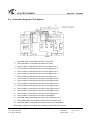
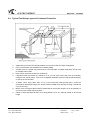
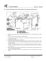
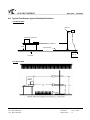
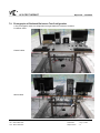
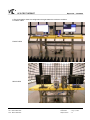
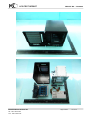
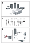
Report No. : JV251566
VCCI TEST REPORT
2.3. Connection Diagram of Test System
1.
The Audio cable is connected from the PC to the EUT.
2.
The RJ45 cable is connected from the PC to the EUT.
3.
The I/O cable is connected from the PC to the support unit 2.
4.
The I/O cable is connected from the PC to the support unit 4.
5.
The I/O cable is connected from the PC to the support unit 5.
6.
The I/O cable is connected from the PC to the support unit 6.
7.
The I/O cable is connected from the PC to the support unit 7.
8.
The I/O cable is connected from the EUT to the support unit 8.
9.
The I/O cable is connected from the EUT to the support unit 9.
10.
The I/O cable is connected from the EUT to the support unit 9.
11.
The I/O cable is connected from the EUT to the support unit 9.
12.
The I/O cable is connected from the EUT to the support unit 10.
13.
The I/O cable is connected from the EUT to the support unit 11.
14.
The I/O cable is connected from the EUT to the support unit 4.
15.
The I/O cable is connected from the EUT to the Adapter.
16.
The HDMI cable is connected from the EUT to the support unit 3.
17.
The D-SUB cable is connected from the EUT to the support unit 3.
18.
The RJ45 cable is connected from the EUT to the remote workstation.
Note: Above support unit on behalf of the meaning, please refer to section 2.2.
Page Number
: 6 of 38
TEL : 886-2-2696-2468
Issued Date
: Aug. 17, 2012
FAX : 886-2-2696-2255
Report Version
: 01
SPORTON International Inc.