1
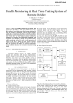
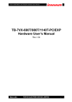
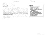
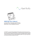
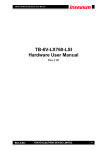
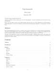
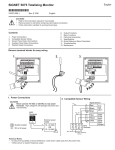
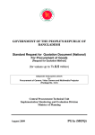
ISD-DEMO1900 REV_A ISD-ES1900_DEMO User Manual Version 0.1 Board version: Rev_A Publication Release Date: Jan 28, 2009 -1- Revision 0.1 ISD-DEMO1900 REV_A Contents Board Overview............................................................................................................................................. 3 PWM vs AUX ............................................................................................................................................. 4 Default settings ......................................................................................................................................... 5 Operation ...................................................................................................................................................... 6 Address Mode operation .......................................................................................................................... 6 Direct Mode Operation ............................................................................................................................. 7 PWM only – vs – AUX only ........................................................................................................................ 8 Note: ............................................................................................................................................................. 9 Board Schematic ......................................................................................................................................... 10 Publication Release Date: Jan 28, 2009 -2- Revision 0.1 ISD-DEMO1900 REV_A Board Overview This manual is for ISD-DEMO1900 Rev_A. Figure 1 -- Top view of ISD-DEMO1900 Rev_A board Publication Release Date: Jan 28, 2009 -3- Revision 0.1 ISD-DEMO1900 REV_A Figure 2 – Top view of demo board PCB silk label PWM vs AUX Based on the output type, the ISD1900 series devices fall into two groups: PWM-Output only and AUXOutput only. Judged by part number, if the device’s part number ends with 01 then it is AUX output only; otherwise it is PWM output only. For example part number “1932SYI” indicates that the device’s output is PWM output. In contrary, “1932SYI01” means device‘s output is AUX output. ISD1900 device PWM output can drive a speaker directly, while AUX output needs to be amplified before driving a speaker. Publication Release Date: Jan 28, 2009 -4- Revision 0.1 ISD-DEMO1900 REV_A For demo boards with AUX output, users can choose either to use the on board LM386 to amplify the ISD1900 device output signal then connect to a speaker, to evaluate the sound; or draw the signal out to their own amplifier for further evaluation. As a reminder, please check what kind of ISD1900 device is populated on your demo board, before heading for further evaluation. Figure 3 is attached below aiming to help user to judge what kind of ISD1900 device is on the demo board. Figure 3 – ISD1900 ordering information AUX out type device has “01” ending. Default settings The following pictures show the default jumper settings Publication Release Date: Jan 28, 2009 -5- Revision 0.1 ISD-DEMO1900 Figure 4 – Address Mode Settings REV_A Figure 5 – Direct Mode Settings Operation The recommended operation sequence is, step by step 1. Connect jumpers, set switch positions, connect speaker; 2. Without power connected, press CHG_MODE button (located at the upper-left corner of the board) to fully discharge the ISD1900 device. This step is to prevent confusion when user changes operation mode between Address Mode and Direct Mode. If device is not fully discharged during mode change, device may stall. 3. Apply power; 4. Use function buttons such as PL (Level-hold play), PE (Edge trigger play), REC and Message buttons (SW1-SW8) to record and playback messages. This board only supports MIC +/- record. o Once power is on and there is no mode change, user can change start address/end address or FMC values (U1 setting) at any time. There is no need to discharge device during operation. Address Mode operation Publication Release Date: Jan 28, 2009 -6- Revision 0.1 ISD-DEMO1900 REV_A No matter what kind of ISD1900 device is used on demo board, for Address Mode operation, jumper settings need to follow the list below: - Address Mode jumper/switches settings (shown in Figure 4): o U1 – put all 4 switches at middle position (floating). o U2 – all 8 switches will be at either left or right position, to indicate a definite start address and an end address. Start address can be any number between 0000 to 1111; End address needs to be equal or greater than the start address. o o J1 – at right, connects 1 &2 Address Mode. Install jumper to choose sampling frequency. In Figure 4, 8 KHz sampling frequency is chosen. - Connect speaker at J6 (if PWM only device), press CHG_MODE once, apply power. *Note: It is always recommended to press CHG_MODE right before applying power. - Since the start address (U3 S0-S3) and the end address (E0-E3) are set, user can now press o PL – level hold play to play; o PE – Edge trigger play to play; o REC – to record Direct Mode Operation No matter what kind of ISD1900 device is used on demo board, for Direct Mode operation, jumper settings need to follow the list below: - Direct Mode jumper/switches settings (shown in Figure 5): o U1 –all 4 switches need be at either left or right position, to indicate a definite FMC value and operation mode: to record or to play. Record or playback U1 REC/R/P is at left (0) position – to record; U1 REC/R/P is at right (1) position – to play; Publication Release Date: Jan 28, 2009 -7- Revision 0.1 ISD-DEMO1900 FMC values table FMC3 FMC2 0 0 0 0 0 1 0 1 1 0 1 0 1 1 1 1 o o o - FMC1 0 1 0 1 0 1 0 1 REV_A Number of messages 1 2 3 4 5 6 7 8 U2 – all 8 switches need be at middle position (floating) J1 – at left, connects 2&3. Install jumper to choose sampling frequency. In Figure 5, 8 KHz sampling frequency is chosen. Connect speaker at J6 (if PWM only device), press CHG_MODE once, apply power, Since the FMC value is set, depends on how many messages can be recorded and playback, user can now press message button M1-M8 to o Record a message if U1 REC/R/P is at left position to record; o Playback a message if U1 REC/R/P is at right position to play. o PWM only – vs – AUX only The only difference between PWM mode and AUX mode operations is that the jumper settings are different. For PWM only devices: - Connect speaker at J6: AUX speaker. - Do not install J9, J10, J11 and J13. For AUX only devices: - Do not install J6. Connect speaker at J13: AUX speaker. J10 connected at 1&2; Aux output signal will be sent to amplifier. Publication Release Date: Jan 28, 2009 -8- Revision 0.1 ISD-DEMO1900 - REV_A J11 connected at 1&2; Aux amplifier will be powered. Note: ISD-DEMO1900 Rev_A has no support on ANAIN recording function. This is a design miss. However, user can wire the signal to MIC+, install Jumper J2 (FT) to evaluate this function. This requires user to modify the board hardware before being able to do so. We will revise the demo board and shall bring user the convenience to evaluate ANAIN record/playback functions with the next version. Publication Release Date: Jan 28, 2009 -9- Revision 0.1 ISD-DEMO1900 REV_A Board Schematic Mode Select: 1->ADDR; 0->DRCT VCCD Chg_Mode VCCD 1 Rec P1 XCLK/FMC3 PE PL 1 SW3 2 1 SW4 2 U2 5k REC PE/FMC2 PL/FMC1 1 VSSD P2 S0 2 S1 3 S2 4 S3 5 PL/FMC1 6 E0 7 VSSA 8 E1 9 R4 E2 10 5k E3 11 P P3 N P4 Tri_State_DIP_4_Switch (EG4516-ND) VCCD U3 2 2 SW5 1 S0 P1 S1 SW6 1 2 SW7 1 2 SW8 1 P N P5 2 SW10 1 VCCD S0/M1 NORM/Mode S1/M2 FT S2/M3 XCLK/FMC3 S3/M4 REC / R/P Play L/FMC1 Play E/FMC2 E0/M5 LED VSSA VCCA E1/M6 ROSC E2/M7 MIC- E3/M8 MIC+ VSSP2 AGC SP- VSSP1 VCCP VCCP SP+ ISD1900 28 Mode VCCD J2 26 FT 25 XCLK/FMC3 24 REC 23 PE/FMC2 22 LED 21 VCCA 20 ROSC 19 MIC- 18 MIC+ C2 2 1 D1 R3 1k 2 1 2 2 SW12 1 53K 1 R5 C1 0.1uF R6 80K R7 100K R11 DNP 1 17 AGC 16 VSSP1 15 SP+ J3 12KHz 2 J4 8KHz 2 J5 6.4KHz 2 0.1uF C3 1 4.7uF 1 J8 2 Sp+ I14B00X Die J6 1 2 P8 HEADER 2_1 Tri_State_DIP_8_Switch (EG4555-ND) SW11 1 VCCD LED VCCA P7 E3 SW1 2 1 Mode_Select 27 PWM SPEAKER + - 2 VSSD R2 5k 1 2 3 Norm P6 E2 SW9 1 VCCP 14 P4 E1 13 SP- P3 S3 E0 12 VSSP2 P2 S2 J1 R1 U1 SW2 2 X1 MIC R8 VCCA C4 4.7K 1 2 4.7uF R9 Knowels (423-1023-ND) 4.7K R10 4.7K 1 AUX AuxOut 2 J9 POWER + - VCCD VCCA VCCA J10 CON3 C13 R12 1.2K 10uF 2 0 3 0 R17 2 R16 GND 1 VCC FB2 3 FB1 1 1 2 VCCP SP+ J7 HEADER 2_1 FB3 J11 CON3 AUX U5 C14 4.7uF 1 2 C15 1uF R13 5k 3 4 VCCD GAIN -INPUT BY PASS +INPUT VS GND VOUT 8 7 6 5 VCCP VCCP VCCA GAIN J13 VCC VCCA VCCD VCCP C16 VCCP R14 C18 C19 0.1uF 10uF C9 C10 C11 C12 C7 C8 C5 C6 10uF 0.1uF 10uF 0.1uF 5k 10uF 0.1uF VSSD 10uF 0.1uF VSSA VSSP2 220uf 1 2 LM386 R15 10 HEADER 2_1 VSSP1 C17 0.047uF AUX SPEAKER Publication Release Date: Jan 28, 2009 - 10 - Revision 0.1