1
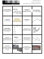
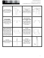
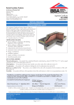
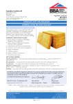
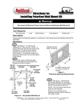
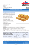
139 Main Road Sorell 7172 t: 1300 737 910 f: 03 6265 3144 w: rainbowbuilding.com.au e: [email protected] INSTRUCTION MANUAL – Garage or Shed Please note: this is a generic instruction manual, please refer to construction notes for a more detailed and specific information about your building. It is crucial that the installer or builder reads this instruction manual thoroughly before commencing any construction. They will also need the construction notes on each individual job which outlines specific measurements, sizes, dimensions and orientations. The following instruction manual is a step by step guide to installing your building but please refer back to the construction notes for more detailed information. Before commencing any building please ensure the following have been met: Council regulations have been satisfied with the appropriate planning, development and building permits and council approvals. All building sites comply with the relevant safety requirements – if in doubt call Workplace Standards Tasmania on 1300 366 322 (same number statewide) Tools checklist: Protective safety gear and clothing: gloves, eye goggles or glasses, sturdy boots. Tape measure, either an 8m or 10m tape and possibly a 30m tape (depending on size of building) String lines Spirit level Markers paint, chalk line, pencils, texta or marker pen Silicon with caulking gun Screw gun with appropriate extension cord Masonry drill with appropriate extension cord Drill bits (see list below) Angle grinder with appropriate extension cord Ladder Tin snips or nibbler Hammer Rivet gun Socket set, spanners, open end spanners to tighten construction bolts Clamps and vice grips Bracing such as rope, tie-down straps or lengths of steel to be used when holding the frame in place 1. Check Bill Of Materials (BOM) or Inventory list The building will have many parts and it is crucial that the pats are checked thoroughly before starting construction for anything that maybe missing, damaged or incorrectly supplied. Please check over the physically delivered parts against the BOM. If you do not have a BOM then contact your nearest Rainbow office for a copy. Below is a list of part names and diagrams for each part, be aware however, for each individual job some parts may not be required and therefore omitted. C – Section purlin Usage: Columns, trusses, mullions, eave purlins (headers), roller door headers Sizes: C100, C150, C200, C250, C300. Tophat Usage: roof and wall girts Sizes: TH64.10 or TH120.10 1 139 Main Road Sorell 7172 t: 1300 737 910 f: 03 6265 3144 w: rainbowbuilding.com.au e: [email protected] Corrugated Cladding Usage: Roof & wall cladding. Skylights have identical profile and cover. Monoclad Cladding (high rib) Usage: Mostly wall cladding, but sometimes roof cladding. K – Panel Cladding (low rib) Usage: Wall cladding. Rolltop Ridge Usage: Ridge capping, apex flashing. Barge Flashing Usage: barge capping in between roof and wall, on gable ends and skillion (i.e. non-gutter walls). Quad Gutter bracket Usage: attaches to wall sheet ribs and mounts quad gutter. Quad Gutter Usage: attaches to wall using quad gutter bracket and collects water runoff from roof. Quad Gutter Stopends Usage: Left Hand (LH) and Right Hand (RH) Caps the end of Quad Gutter. Knee Bracket Usage: bolts column and truss together on the left and right hand side of the building (LH & RH) *C150 shown. Ridge Bracket Usage: used to bolt together both trusses in the centre of the gable (apex) *C150 shown. 2 139 Main Road Sorell 7172 t: 1300 737 910 f: 03 6265 3144 w: rainbowbuilding.com.au e: [email protected] Eave Purlin Bracket Usage: a U-shaped bracket that sits on top of the column that is used to join the eave purlin to the column. Rear Mullion Connector Bracket Usage: an L-shaped bracket that allows the mullion (or gable end column) to attach to the truss on the gable wall. Roller door Mullion Connector Bracket Usage: a flat plate that allows the mullion (or gable end column) to attach to the underside of the truss on the gable wall ready for roller door mounting. Roller door Mullion Connector Bracket (offset for two roller doors in gable end) Usage: a flat plate that allows the mullion (or gable end column) to attach to the underside of the truss on the gable wall ready for roller door mounting. End Wall Girt Bracket Usage: L shaped bracket (unpunched) used to connect tophat wall girts to the inside of columns on the gable (nongutter wall) walls only. Also used to attach roller door headers in between roller door mullions/columns. Comes in sizes to suit 64mm or 120mm tophats depending on your tophat wall girt size. Baseplate Usage: L shaped bracket (punched) used to connect the bottom of the columns to the concrete slab or concrete footings. Acts much like a ‘foot’ and comes in sizes to suit your columns, either C150, C200, C250 or C300. Tophat Lap Usage: ensure the tophats are lapped and screwed using Shedteks to the columns and trusses accordingly. Downpipes including; downpipe (1.8m or 2.4m long), nozzle or pop, downpipe straps Usage: diverts water from gutter to ground and into watertank or stormwater. 3 139 Main Road Sorell 7172 t: 1300 737 910 f: 03 6265 3144 w: rainbowbuilding.com.au e: [email protected] Corner Flashings Usage: capping for external corners and around roller doors. Roller Doors Including the door itself, mounting brackets and tracks. Can be placed in gable wall or side wall. Roller door motors Usage: remotely open and close roller doors *MR850 Slimdrive model shown Windows and Glass sliders and PA doors Usage: offers natural light and ventilation while glass sliders act as entry points. All packaged in a box. Windows require jambs for installation. PA door Usage: PA door act as entry points. All packaged in a box. PA doors require jambs for installation. PA door and Window Jambs Usage: this U-shaped channel creates a stud opening for the insertion of PA doors and windows, slots into the horizontal tophat. Sisal and Wire/Mesh Usage: sits underneath the roof sheets and helps reduce the dripping effect caused by condensation. Aircell Usage: great for sheds, acts as a 3-1 product for condensation, thermal break, breathable insulation (effective cover 25m² per roll). Fasteners TYPE SIZE TOOL FINISH USAGE Roof Zips Wall Screws Framing Screws Button Heads Waffer Heads Rivets Framing Bolts Fascia Bolts Framing Bolts Dynabolts Dynabolts M6 x 50 10-16 x 16 Shed Tek 14-20x22 Tek 10-16 x 16 4-3 M16x30 2 washers M16x30 1 washer M12x30 1/2washers 12x75 Hex Head 12x105 Hex Head 5/16 or 8mm hex head 5/16 or 8mm hex head 5/16 or 8mm hex head Philips head screw driver Philips head screw driver Colour Colour Zinc Zinc Zinc Colour Zinc Zinc Zinc Zinc Zinc Screw roof sheets & barge to tophat roof girts Screw wall sheets to tophat wall girts Screw tophats to columns/trusses/eave purlins Attach gutter brackets to top of wall sheet Used to frame up PA door/window channel Attach flashings, barge, gutter, stop ends Main framing bolts for punched brackets Framing for garaports & around R/Doors R/Door mullions in side wall (C100’s) PA door channel & R/Door mullions in side wall Bolt down all columns and R/Door in gable wall 3mm drill bit for pilot holes 15/16 or 24mm socket 15/16 or 24mm socket 15/16 or 24mm socket 5/8 or 16mm socket 5/8 or 16mm socket 4 139 Main Road Sorell 7172 t: 1300 737 910 f: 03 6265 3144 w: rainbowbuilding.com.au e: [email protected] 2. Layout all columns and trusses (C-section purlins) on ground and using the LH knee and RH knee and ridge connection brackets supplied to line up all holes so you have a finished portal frame. Bolt off using framing bolts and ensure dimensions are identical for external measurements and that ALL frame portals are the same width, height and orientation by placing each portal frame on top of each other. 3. Bolt the base cleats (L-shaped bracket with 2 holes on each plane; see page 3 for details) to each of the columns using M16 x 30 Purlin bolt. DO NOT attempt to dynabolt the base cleat to the concrete slab or concrete footings just yet. 4. You may see Fascia Bolts (M16x30 FASCIA bolt and nut) on your Bill Of Materials list. These bolts have a flatter head and no washers and need to be used around columns and mullions in and around any roller doors instead of the standard fatter head framing bolt (M16 x 30 Purlin assembly). This is so the roller door track does not flair out when screwing the roller door track to the mullion framing. Fascia Bolts (e.g. M16x30 FASCIA bolt and nut) are also used if you have a garaport (i.e. a carport attached to a garage with the same roof line). They are to be used on the front gable (pitched end) instead of the fatter head framing bolts (M16 x 30 Purlin assembly) to ensure the barge flashing does not flex outwards when screwing and riveting the barge flashing to the front of the garaport (to the truss normally). Once again this application is better than using the standard fatter head framing bolts. a. Please check that the orientation of the columns (i.e. the ‘C’ section) is correct for roller doors. This is to ensure the roller door framing is orientated the correct way as to attach the roller door mounting brackets and tracks. Fascia Bolts 5. Repeat process for all gable portals and sit them on top of each other which will allow you to double check all portals have the same dimensions. If your shed or garage requires the use of knee and ridge bracing (or cross bracing) now is the time to install this. Refer to your construction notes for more info. Usually if your shed is 9.0m wide or greater, then knee and ridge bracing is required. 6. Stand one portal frame up and into position onto slab (or footings) and brace off to the ground using rope, straps or a length of timber or steel which is securely fastened to the ground. 5 139 Main Road Sorell 7172 t: 1300 737 910 f: 03 6265 3144 w: rainbowbuilding.com.au e: [email protected] 7. When moving onto the next portal, brace each preceding portal to the next one using a roof tophat girt. The exact positioning of the portal frames onto a concrete slab from the side wall (or gutter length wall) is inset 64mm from the edge of the slab (if your shed is using TH64.10 wall tophats girts) OR 120mm from the edge of the slab (only if your shed is using TH120.10 wall tophat girts). However the columns will set flush with the gable end of the slab. This will ensure that the wall tophats girts run continuous and overlap along the side wall (gutter wall) but the wall tophats will run flush with the gable walls. Check your BOM to see what size tophats has been supplied for your shed. To attach the wall tophat girts to the inside of the columns on the gable walls (non-gutter walls), use the plain L shaped End Wall Girt Bracket. See page 3 for connection details. Use shedtek framing screws to attach the bracket to the column and tophat wall girt. 8. Secure the base cleats to the concrete slab or concrete footings by using the applicable dynabolts. Using only one per columns at this stage would be fine as long as other bracing is used in the meantime. 9. Start to attach each eave purlin (C-section purlin, usually smaller in size) using an eave purlin bracket (U shaped bracket). This will also ensure that your portal frames are separated at the correct spacing’s. Eave purlins are used to attach columns together on a horizontal axis. The eave purlin bracket has to be set 15mm down from the top of the column and the top of the eave purlin (usually a C100) has to be set directly inline with the top of your columns (11 degree roof pitch). However if you have a skillion roof shed (5 deg roof pitch) the eave purlin bracket on the high side only does not need to be set down, the eave purlin bracket has to be in line with the top of the column. Therefore the eave purlin header on the high side only will sit 13mm above the top of the column. The low side of the skillion shed still follows the 15mm set down rule as with all gable roof sheds above. Slide the eave purlin bracket over the column and knee bracket and using 4 shed tek framing screws per eave purlin bracket (2 per side of the column) screw the eave purlin bracket into place. See “Eave Purlin Bracket” on page 3 for more detail. The eave purlin has to be set outwards from the column to fall exactly inline with the wall girts so the wall sheets line up on a straight vertical axis. Eave purlins determine your bay spacings; therefore it is essential that you DO NOT CUT YOUR EAVE PURLINS! They are supplied the exact length that is required. It is also important that they must butt up against each other in the middle of the column and not overlap. 10. Continue to attach all roof tophats using 8 shed tek framing screws per overlapping connection (see page 3, “Tophat Lap”) and check the construction notes for tophat spacing’s. Once they have all have been secured in place and all eave purlins are located along the length of the building, you can now install the mullions (C-section purlin) at each gable wall ensuring the orientation and layout is correct. See “Rear Mullion Connector Bracket” and “Roller door Mullion Connector Bracket” and “Roller door Mullion Connector Bracket” on page 3 for more details about shed tek framing screw connections and shed tek connection quantities. 11. All the remaining wall tophats can now be screwed to the columns at the correct spacing’s. Check the construction notes for tophat positioning and spacing’s. Also see “Tophat Lap” on page 3 for connection details using shed tek framing screws. *The sketch below is only a guide, each individual job may or may not have strap bracing and more or less tophat wall girts. Refer to construction notes for specific details. 6 139 Main Road Sorell 7172 t: 1300 737 910 f: 03 6265 3144 w: rainbowbuilding.com.au e: [email protected] 12. Once all roof and wall girts and eave purlins are in place, you should have a finished product that looks like the diagram above. IT IS CRUCIAL THAT YOU MEASURE ALL FRAME WIDTHS, LENGTHS AND DIAOGNAL DIMENSIONS ON ALL SIDES OF THE BUIDING WITH A STRING LINE BEFORE COMMENCING SHEETING. Now is the time to finish dynabolting all remaining columns and mullions to the concrete slab or concrete pads. 13. If your building has sisalation paper and support mesh, now is the time to install the support mesh. Each run of wire can be looped around the eave purlin and twisted around on itself much like a fence. There is no need to pull the wire tight, the wire is merely there to prevent the sisalation paper from sagging in between the roof tophats. 14. Start to sheet the side walls (the gutter length wall) from one side to the other. Start sheeting the end of the building that is as far away as the direction of the prevailing weather. See “Cladding Layout” in your construction notes for more detail about which sheet to start first and where each sheet is intended to go. See below diagram for fastening and lapping details: Direction of prevailing weather Direction of laying sheets 15. Sheet gable walls next but this time starting with laying the first sheet in the middle of the gable and working from the centre out to left. And then to the right. See “Cladding Layout” in your construction notes for more detail about which sheet to start first and where each sheet is intended to go. If the roller doors are located in the gable wall sheet this gable wall after the roller doors have been installed. 16. Install gutter by firstly screwing the gutter brackets to the wall sheets. It is best to screw the brackets into the wall sheets where they overlap, giving the bracket more material to attach to. It is important that gutters slope toward the outlet (gutter pop and downpipe). A minimum gutter fall of 1 in 500 is recommended so the water will run to one end of the building and not ‘pool’. 17. It is now time to start cladding the roof, but if your building has sisalation paper or Aircell, you will need to follow the installation instructions on the corresponding packaging to ensure this is installed correctly. Please note: Aircell does not require support mesh. 18. Install roof cladding by following the diagram below to ensure the right lapping and laying of the sheets: 7 139 Main Road Sorell 7172 t: 1300 737 910 f: 03 6265 3144 w: rainbowbuilding.com.au e: [email protected] Direction of prevailing weather Direction of laying sheets (above) Use roof zips to screw roof sheets to tophat roof girt in this fashion for middle roof tophats (i.e. not eave purlin). (above) Use roof zips to screw roof sheets to eave purlin in this fashion (i.e. every second rib) When installing the roof sheets, bend up all the top valleys at the top of the sheet which will sit under the ridge capping. This will act as a barrier to weather, birds, dust, leaves and any other debris the wind can blow around. 19. Penetrations such as PA doors and windows can now be installed in the walls. The use of channel framing (jambs) will create the stud opening sizes suitable for PA doors and windows. The open Ushape of the channel should slot into and overlap the wall tophat girt. Ideally, it is best to sit a window on top of a tophat wall girt for extra stability. Use applicable flashings above the PA door and window to prevent leakage. The PA door channel framing has smaller dynabolts that are used to anchor the channel to the slab or small footing. The window has a specific instruction manual within its box. 20. Install roller doors onto the supplied brackets but do not unwrap the roller doors until the tracks are installed. Unwrapping the roller doors should be the last thing you do as this reduces the risk of roller door damage and the roller door from losing tension. Follow the instruction manual on roller doors (either found inside the roller door bracket box OR inside the door drum OR see the bottom of this manual for more details). Situate the roller door header (C-section purlin) using end wall girt brackets at a height approx 350 - 400mm less than the wall height of the building. This allows enough clearance to be obtained once the roller door is rolled up. 21. Finish wall sheets around gable wall and where roller doors are (if applicable) 22. Attach all corner flashings and roller door flashings (either 50mm x 50mm or greater) using rivets evenly spaced and silicon where necessary. 23. Attach the barge flashing using a combo of coloured wall screws and rivets evenly spaced. Remember not to screw the barge flashing too tightly to the walls as this causes flexing and can look unsightly. 24. Attach the ridge capping with a practical amount of overlap at the joins and use silicon where necessary. 25. Sweep down and hose off the roof area to remove any swath or unwanted sharp pieces of metal, screws etc… Pay close attention to removing metal particles or debris from the gutter to prevent staining or corrosion. 8