1
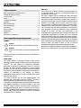
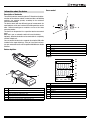
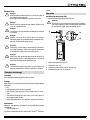
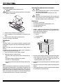
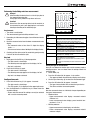
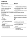
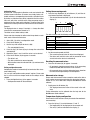
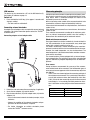
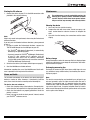
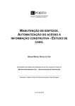
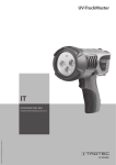
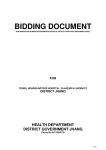
T510
EN
TRT-BA-T510-TC-001-EN
OPERATING MANUAL
MATERIAL MOISTURE
MEASURING DEVICE
Warranty
Table of contents
Notes regarding the operating manual .................................... 1
Information about the device................................................... 2
Technical data ........................................................................ 3
Safety ..................................................................................... 3
Transport and storage............................................................. 4
Operation................................................................................ 4
Measuring principle ................................................................ 9
Table of wood types................................................................ 13
PC software ............................................................................ 13
Errors and faults ..................................................................... 14
Maintenance ........................................................................... 14
Disposal.................................................................................. 15
Declaration of conformity ........................................................ 15
Notes regarding the operating manual
Symbols
Danger!
Warns of a hazard which can lead to personal injury.
Caution!
Warns of a hazard which can lead to damage to property.
The warranty is for 12 months. Damages caused by incorrect use
by untrained people or start-up by unauthorised people are
excluded from the warranty.
The device complies with the fundamental health and safety
requirements of the applicable EU regulations and was tested at
the factory for perfect functionality multiple times. However, if
faults in the functionality occur and cannot be remedied with the
measures in the chapter Errors and faults, please get in touch
with your dealer or distributor. When making a warranty claim,
supply the device number (see the rear of the device). The invoice
acts as warranty certificate. When manufacturer's instructions or
legal regulations have not been followed, or after unauthorised
changes to the device are made, the manufacturer is not
responsible for the resulting damages. Changes to the device or
unauthorised replacement of individual parts can drastically
impact the electrical safety of this product and leads to the forfeit
of the warranty. Liability does not extend to damages to people or
property caused by the device being used other than as described
in the instructions in this operating manual. Subject to changes to
technical design and model changes as part of constant
development and product improvement without prior notice.
No liability is accepted for damages resulting from improper use.
In such cases, entitlements to a warranty are then also forfeited.
The current version of the operating manual can be found at:
www.trotec.de
Legal notice
This release replaces all previous versions. No part of this
publication may be reproduced without written permission from
TROTEC®. The same applies for electronically processing,
duplicating or spreading the publication. Subject to technical
changes. All rights reserved. Trademarks are used without
guarantee that they may be used freely and primarily following
the spelling of the manufacturer. Product names are registered.
Changes to construction in the interests of constant
improvements to the product, as well as changes to the shape
and colour are reserved.
The scope of delivery may vary from product images. This
document was created with all due care. TROTEC® accepts no
liability whatsoever for possible mistakes or omissions.
The only party responsible for determining measured results to be
valid, drawing conclusions and deriving actions is the user!
TROTEC® accepts no claims of warranty for the correctness of
the determined measured values or measured results. Further,
TROTEC® accepts no liability whatsoever for possible mistakes or
damage which have been caused by utilising the determined
measured results. © TROTEC®
1
Operating manual – Material moisture measuring device T510
EN
Cross control
Information about the device
7
Description of the device
The material moisture measuring device T510 enables the determination of the moisture content in wood and other soft building
materials (e.g. gypsum, plaster) according to the resistance
measurement method.
The device comes with two different types of measurement: for
wood moisture on the one hand and for building moisture on the
other. Different wood types or materials can be set for these
measuring modes.
The device can be operated via a capacitive touchscreen control
panel.
When not in use, an automatic switch-off saves the battery.
Optionally, different electrodes can be connected via a separately
available adapter set.
You can connect the device to a computer by using the USB cable
included in the scope of delivery. Then you can extract and analyse your measured results with the optional MultiMeasure Studio
software.
Device depiction
1
11
8
10
9
No.
Operating element
7
8
9
10
11
Up key
Right/back key
Down key
OK button
Left/menu key
Display
TH
HOLD
2
IR
MAX
MIN
DP
CFG
AVG ACT
12
13
14
%WT
CM
m/s
ppm °F °C
16
6
3
5
4
No.
Operating element
1
2
3
4
5
6
Display
Cross control
Battery compartment with battery cover
On/Off key
USB interface
Connections for measuring tips with protective cap
EN
15
g/m3 g/kg gr/lb dp °C °F % rH
17
Pabs[hPa]
SENS
MAT
18
Alt.[ft]
TEMP
No.
Display element
12
13
14
15
16
17
18
Configuration mode display
Measuring mode
Measurement value display top
Percentage
Measurement value display bottom
Temperature unit
Configuration mode
Operating manual – Material moisture measuring device T510
CAL12
Alarm
2
Technical data
Safety
Parameter
Value
Model
Dimensions (L x W x H)
Weight
T510
174 mm x 63 mm x 35 mm
approx. 300 g
Measuring range for building moisture
Measuring range
Resolution
0 to 100 digits
1 digits
Measuring range for wood moisture
Wood moisture
Tolerance (based on the measuring principle)
Resolution
Operating temperature
Storage temperature
Battery
Optional power supply
Current consumption, active
Current consumption, passive
Battery lifespan, active
0 to 100 M%
0 to 5 M%: ±0.8 M%
5 to 30 M%: ±0.2 M%
30 to 100 M%: ±0.1 M%
0.1 M%
0 °C to +50 °C with
< 90 % or < 20 g/m3
(non-condensing)
-20 °C to +60 °C with
< 90 % or < 20 g/m3
(non-condensing)
4 x Alkaline LR6 AA batteries,
1.5 V
or NiMH rechargeable batteries
(>2500 mAh)
5 V USB
Approx. 80 mA
Approx. 70 μA
> 30 h
Scope of delivery
The scope of delivery includes:
• 1 x Material moisture measuring device T510
• 4 x Alkaline LR6 AA, 1.5 V batteries
• 1 x USB cable
• 1 x Protective cap for measuring tips
• 10 x Measuring tips
• 1 x Table of wood types, printout
• 1 x Display protection film
• 1 x Getting started guide
• 1 x Factory test certificate
3
Carefully read the operating manual before using the device
and keep it within reach!
• Do not use the device in atmospheres containing oil, sulphur,
chlorine or salt.
• Never use the device for measurements at live parts.
• Never perform measurements on a metal surface.
• Ensure that all connection cables are protected from
damages (e.g. from kinks or crushing).
• Protect the device from permanent direct sunlight.
• Observe the storage and operating conditions (see chapter
Transport and storage).
Intended use
Only use the material moisture measuring device T510 to
measure the moisture content of wood and other soft building
materials (e.g. gypsum, plaster). Here, read and observe the
technical data.
To use the device for its intended use, only connect and use
accessories and spare parts which have been approved by
TROTEC®.
Improper use
Do not use the device in potentially explosive atmospheres, or for
measurements in liquids. TROTEC® accepts no liability for
damages resulting from improper use. In such a case,
entitlements to a warranty are forfeited. Any unauthorised
modifications, alterations or structural changes to the device are
forbidden.
Personnel qualifications
People who use this device must:
• have read and understood the operating manual, especially
the Safety chapter.
For maintenance or repair work which requires the housing
to be opened, contact TROTEC® customer service. Devices
which have been opened unlawfully are void of any warranty
and warranty claims.
Operating manual – Material moisture measuring device T510
EN
service.
Residual risks
Danger!
When handling the device there is a risk of injury due to
the exposed measuring tips.
Always put on the protective cap when not in use.
Danger!
Do not leave the packaging lying around. Children may
use it as a dangerous toy.
Operation
Installing the measuring tips
• Mount the measuring tips before first use.
Caution!
Exclusively use the original measuring tips included in
the scope of delivery. Other measuring tips might bend
or damage the holder at the measuring device.
Danger!
The device is not a toy and does not belong in the hands
of children.
21
Danger!
Dangers can occur at the device when it is used by
untrained people in an unprofessional or improper way.
Observe the personnel qualifications.
19
20
Caution!
Exclusively use the original measuring tips included in
the scope of delivery. Other measuring tips might bend
or damage the holder at the measuring device.
Caution!
Never force the measuring device into the material to
be measured or yank it out. Applying force can lead to
bending or breaking of the measuring tips.
Caution!
To prevent damages to the device, do not expose it to
extreme temperatures, extreme humidity or moisture.
1.
2.
3.
4.
Remove the protective cap (21).
Detach the nuts (19)
Insert the measuring tips (20) in the nuts (19).
Remount the nuts (19) on the device.
Transport and storage
Transport
Use a suitable bag to transport the device safely.
Storage
When the device is not being used, observe the following storage
conditions:
• dry,
• protected from dust and direct sunlight,
• with a plastic cover to protect it from invasive dust, if necessary.
• The storage temperature is the same as the range given in
the chapter Technical data.
• When storing the device for a long time, remove the batteries.
Accessories
Optionally, the following accessories are available for transport
and storage:
• TROTEC® Holster 3
For further information please contact your TROTEC® customer
EN
Operating manual – Material moisture measuring device T510
4
Inserting the batteries
Performing the wood moisture measurement
• Insert the supplied batteries before first use.
Caution!
Make certain that the surface of the device is dry and the
device is switched off.
Danger!
When handling the device there is a risk of injury due to
the exposed measuring tips.
Always put on the protective cap when not in use.
Caution!
Never force the measuring device into the material to
be measured or yank it out. Applying force can lead to
bending or breaking of the measuring tips.
Requirements:
• The device is switched on.
• The measurement type for wood moisture is set.
• The wood temperature is set.
• The wood type is set.
1. Open the cover of the battery compartment (3).
2. Insert the batteries in the compartment as indicated in the
figure.
3. Close the cover of the battery compartment (3).
The device can now be switched on.
1. Choose a suitable measuring position. The measurement is
not to be performed at places with visible deficiencies (e.g.
cracks, resin pockets, branches).
Further observe the following:
– a = 30 cm
– c = insertion depth
– d = thickness
Switching on
Note:
The cross control is very sensitive. Therefore, avoid dirt on the
control panel, because it could be misinterpreted by the device as
keystroke.
Before use make sure that the touchscreen control panel is
dirt-free.
If required clean the touchscreen control panel according to
chapter Cleaning the device on page 14.
1. Press the On/Off key (4) until a beep is emitted.
2. The device performs a short self-test.
– The device name and firmware version is shown on the display.
– The battery charge is indicated on the display.
– The device is ready for operation.
– The displayed units are based on the settings of the last utilization.
Notes:
Note that moving from a cold area to a warm area can lead to condensation forming on the device's circuit board. This physical and
unavoidable effect can falsify the measurement. In this case, the
display shows either no measured values or they are incorrect.
Wait a few minutes until the device has become adjusted to the
changed conditions before carrying out a measurement.
5
a
c
d
a
a
2. Insert the measuring tips transverse to the fibre direction with
a 30 cm distance to one of the two ends of the sawn timber.
– If the good to be measured is shorter than 60 cm, the
measuring position is the in the centre.
3. If possible, prick the measuring tips a few millimetres into the
material.
4. Read the measured value from the upper measurement value
display.
5. Carefully pull the device out of the material by gently moving
it in turns to the left and to the right.
Operating manual – Material moisture measuring device T510
EN
Performing the building moisture measurement
TH
HOLD
Danger!
When handling the device there is a risk of injury due to
the exposed measuring tips.
Always put on the protective cap when not in use.
1. If possible, prick the measuring tips a few millimetres into the
material.
2. Read the measured value from the lower measurement value
display.
– For measured values of less than 15 digits the display
reads: ----.
– For measured values above 100 digits the display flashes.
3. Carefully pull the device out of the material by gently moving
it in turns to the left and to the right.
%WT
1. Briefly press the On/Off key (4) during operation.
– The device emits a short beep.
– The following message appears on the display: LoC on.
– Key lock is activated.
2. Press the On/Off key (4) again.
– The device emits a short beep.
– The following message appears on the display: LoC off.
– Key lock is no longer activated.
Configuration mode
1. Press the Left/menu key (11) for approx. 2 seconds.
– The device emits a short beep.
– The CFG symbol (12) is displayed in the upper right corner.
2. Use the Right/back or Left/menu key to choose from the
available settings.
– Please note that some of the settings can only be selected
with a certain measuring mode.
EN
DP
CFG
AVG ACT
12
CM
m/s
ppm °F °C
16
g/m3 g/kg gr/lb dp °C °F % rH
Pabs[hPa]
SENS
MAT
Configuration
mode
Lamp
SENS
MAT
TEMP
Alarm
CAL
Key lock
MIN
14
Caution!
Never force the measuring device into the material to
be measured or yank it out. Applying force can lead to
bending or breaking of the measuring tips.
Requirements:
• The device is switched on.
• The measurement type for building moisture is set.
IR
MAX
Alt.[ft]
TEMP
CAL12
Alarm
18
Description
Setting brightness.
Available are values between 20 and 100 % and AL.on.
Switch-off after 30 min unless with setting AL.on.
Selecting the sensor mode, available settings are Wood
and Build.
Only available in sensor mode Wood.
Selection of different wood types, see table of wood types.
Only available in sensor mode Wood.
Setting the value for wood temperature (fixed value only,
no measurement, value range between -20 and +60 °C).
Setting the alarm value.
value range: 0 to 100 digits or M%
Setting the offset value.
Will be added to the measured value.
value range for the wood moisture measurement: -50 to
+50 M%
value range for the building moisture measurement: -50 to
+50 digits
Setting the type of measurement
Here you can determine whether you want to measure wood or
building moisture. You can choose from the settings Wood 120
and Build 100.
1. Select SENS (18).
2. Press the OK button (10) for approx. 2 s to confirm.
– The upper and lower measured value displays are flashing.
3. Use the Up or Down key (9) to select the measurement type.
4. Press the OK button (10) for approx. 2 seconds.
– The type of measurement was set based on your choice.
– The device switches to measuring mode.
Note:
How the measured values are indicated, changes depending on
the type of measurement.
• Wood moisture:
– Upper measurement value display: measured material
moisture in %.
– Lower measurement value display: preset material temperature in °C or °F.
• Building moisture:
– Upper measurement value display: no indication.
– Lower measurement value display: measured material
moisture in digits.
Operating manual – Material moisture measuring device T510
6
Adjusting the display illumination
The display illumination can be adjusted within a range of 20 to
100 %. Another available setting is AL.on. AL.on features a
brightness of 100 % and deactivates the automatic switch-off
function.
1. Select the lamp (18) whilst in configuration mode.
2. Press the OK button (10) to confirm.
3. Select the desired value by use of the Up (7) or Down (9) key.
4. Press the OK button (10) for approx. 2 seconds.
– The set value will be adopted.
The device switches to measuring mode.
Setting the alarm
Here you can determine the limit value for the alarm function.
Upon exceeding this value, the device emits an acoustic signal
and the indication ALARM (18) flashes. The alarm function draws
on the current measured value. The limit value can be determined
within a range of 0 to 100.
1. Select ALARM (18).
2. Press the OK button (10) to confirm.
– The upper measurement value display (14) flashes.
3. Press the Up (7) or Down (9) key to activate or deactivate the
alarm.
– On or Off will be indicated in the upper measurement value
display (14).
4. Press the Right key (8).
– Depending on the selection, the alarm is either activated or
deactivated.
– The lower measurement value display (16) flashes.
5. Press the keys Right/back (8) or Left/menu (11) to select a
digit.
– The selected digit flashes.
6. Press the Up (7) or Down (9) key to change the value of the
selected digit.
7. Repeat the steps 5. and 6. until the value is set as desired.
8. Press the OK button (10) for approx. 2 seconds.
– The alarm was set based on your choice.
– The device switches to measuring mode.
– With activated alarm function the indication ALARM (18)
continues to be displayed.
7
Material settings
Please note that this function can only be selected for wood moisture measuring.
1. Select MAT (18) whilst in configuration mode.
2. Press the OK button (10) for approx. 2 seconds.
– Code be indicated in the upper measurement value display.
– The current material code (see chapter Table of wood
types) is indicated in the lower measurement value display.
3. Press the keys Right/back (8) or Left/menu (11) to select a
digit.
– The selected digit flashes.
4. Press the Up (7) or Down (9) key to change the value of the
selected digit.
5. Repeat the steps 3. and 4. until the value is set as desired.
6. Press the OK button (10) for approx. 2 seconds.
– The desired material is set.
– The device switches to measuring mode.
Setting the wood temperature
Please note that this function can only be selected for wood moisture measuring.
Via this function you can determine the wood temperature in
degrees Celsius (°C) or Fahrenheit (°F). The wood temperature is
required by the device in order to determine the exact material
moisture.
Note:
Determine the wood temperature prior to the measurement, e.g.
using a pyrometer.
1. Select TEMP (18) whilst in configuration mode.
2. Press the OK button (10) for approx. 2 seconds.
– The currently set wood temperature is indicated in the lower measurement value display.
3. Use the keys Left or Right to select a digit.
– The selected digit flashes.
4. Press the Up (7) or Down (9) key to change the value of the
selected digit.
5. Repeat the steps 3. and 4. until the value is set as desired.
6. Press the OK button (10) for approx. 2 seconds.
– The wood temperature is set.
– The device switches to measuring mode.
Operating manual – Material moisture measuring device T510
EN
Setting the offset
By use of CAL a single-point calibration can be carried out for the
selected sensor indications. All sensors are already factory-calibrated and have a corresponding characteristic calibration curve.
By stating a calibration value (offset) a global shift of the calibration curve, which has an effect on the entire measuring range, is
performed for the single-point calibration! The offset value to be
entered is that value by which the calibration curve will be shifted.
Setting the measuring mode
1. Press the keys Right/back (8) or Left/menu (11) until the desired measuring mode is displayed.
– The selected measuring mode (13) will be indicated on the
display (1).
Example:
The displayed value is always 5 too high => change the offset
value for this measurement channel to -5.
The offset value's default setting is 0.0.
TH
HOLD
IR
MAX
MIN
%WT
CM
m/s
DP
CFG
AVG ACT
13
ppm °F °C
The device comes with the following measuring modes:
Please note that changing the offset value brings about an automatic reset of the measured values.
1. Select CAL (14) whilst in configuration mode.
2. Press the OK button (10).
3. Use the keys Left or Right to select a digit.
– The selected digit flashes.
4. Press the Up (7) or Down (9) key to change the value of the
selected digit.
5. Repeat the steps 3. and 4. until the value is set as desired.
6. Press the OK button (10) for approx. 2 seconds.
– The offset is set.
– The device switches to measuring mode.
– With set offset value the indication CAL (14) continues to be
displayed.
Exiting configuration mode
Configuration mode will automatically be terminated after 8 seconds without entry.
You can quit configuration mode yourself anytime. Please note
that in such an event no changes made to the settings will be
adopted.
1. Press the Right/back key (8) for approx. 2 seconds.
– Configuration mode will be terminated.
Measuring
mode
Description
ACT
AVG
MIN
MAX
HOLD
Measured value in real time
Average value of measurements since switch-on
Minimum measured value
Maximum measured value
Measured value will be held
Holding the measured value
1. Set the measuring mode to HOLD.
– The current measured value will be held and displayed.
– The device will hold this value until the measured values
are set back or the device is switched off.
Resetting the measured values
1. Press the OK button (10) for approx. 2 seconds.
– All previously stored measured values of the measuring
modes AVG, MIN, MAX and HOLD will be set back.
– All measured values are then determined anew based on
the measurement proceeding in the background.
Measured value storage
Please note that measured values cannot be saved on the device
itself. In order to save measured values, the device has to be connected to a PC via a USB cable using the MultiMeasure Studio
software.
1. Briefly press the OK button (10).
– The displayed measured value will be saved in the software.
Further information can be gathered from the help text of the
MultiMeasure Studio software.
Temperature display configuration
Please note that this function can only be selected for wood moisture measuring.
1. Press the Up key (7) to switch between °C and °F.
– The temperature will be displayed in the selected unit.
– The unit (15) will be indicated on the display (1).
EN
Operating manual – Material moisture measuring device T510
8
USB interface
Measuring principle
The device can be connected to a PC via the USB interface (5).
See chapter PC software on page 13.
Switch-off
1. Press and hold the On/Off key (4) for approx. 3 seconds until
a beep is emitted.
– The device will be switched off.
Connecting external electrodes
An adapter set and adapter cable are required to connect external
electrodes. For further information please contact the TROTEC®
customer service.
Connecting adapter set and adapter cable
22
23
25
Wood moisture measurement
Every type of wood has a distinct conductivity. In order to take this
fact into consideration for the measurement, every wood type
comes with a material code that can be set.
The wood's conductivity is further influenced by the wood temperature. In order to take this fact into consideration for the measurement, the wood temperature can also be determined. The
wood temperature is to be determined before moisture measurement and set accordingly.
The measuring device comes equipped with an internal temperature compensation. The resistance curves of the selected wood
type are automatically adapted depending on the set wood temperature.
Error sources
During resistance measurement the accuracy of the measurement method needs to be examined. Two fundamental types of
error sources become apparent within the measuring range from
0 to 100 M%.
• There is one error stemming from the measuring principle of
the resistance measurement. This is particularly noticeable in
case of high resistance values (low conductivity at less than
5 M%). Due to the low measuring currents the measurement
value display is i.a. increasingly falsified by molecular attraction. Listed below are the principle-related measurement errors:
24
1. Detach the nuts and remove the measuring tips, if applicable.
2. Screw the two adapters (22) onto the device.
3. Plug the two cable ends (25) of the adapter cable (23) into the
adapters (22).
– You can now connect external electrodes (example: (24)) to
the device.
– Observe the condition of the external electrodes and prepare these for the measurement, if required.
– For further information on suitable electrodes please
contact the TROTEC® customer service.
9
During moisture measurement according to the resistance principle an electric measuring current is generated within the measuring device, which is conducted through the material to be
measured by means of electrodes.
With an increasing water content of the measured material to be
examined the resistance drops and conductivity builds up.
If the material to be measured has a high resistance, the moisture
content is low.
If the material to be measured has a low resistance, the moisture
content is high.
Thus, moisture measurement according to the resistance principle is an indirect measurement method, since the humidity is
deduced from the conductivity of the measured material.
Measured value
Error
0 - 5 M%
6 - 30 M%
31 - 100 M%
0.8 M%
0.2 M%
0.1 M%
Operating manual – Material moisture measuring device T510
EN
• The other typical error source to be considered is material
characteristics. This is particularly noticeable in case of high
moisture contents above the fibre saturation point (high conductivity above 30 M%). Owing to the irregular cellular structure of various wood types and the i.a. resulting irregular
water retention within and outside of the cells, these measured values in part substantially deviate from the actual
moisture contents. It is, however, not possible to put a precise number on these deviations, even though the principle-related accuracies with 0.1 M% suggest a higher
accuracy than for the medium measuring range from 6 to 30
M%.
When looking at both error sources, one can conclude, that the
resistance measurement method is particularly well suited for the
determination of the moisture content between 6 and 30 M%.
Notes regarding the wood moisture measurement
• Make sure you have set the correct type of measurement
(wood).
• Make sure that the correct material code was selected.
• Prior to the actual measurement process, check the
temperature conditions. To do so, for instance a pyrometer is
to be used for measuring the surface temperature of the
wood type, which should then be compared with the wood
temperature set in the device. If both temperatures are
identical, measuring can be started.
If the wood temperature is higher than the value set in the
measuring device, a higher wood moisture than really there
will be displayed as a result.
• When measuring sawn timber, observe the instructions of
DIN EN 13183-2.
• Always insert the measuring tips transverse to the wood fibre
direction.
The conductivity transverse to the wood fibre direction is lower than that in line with it.
Depending on the type of wood it varies by the factor 2.3 to 8.
EN
• When selecting the measuring positions observe the following:
– Always measure the material moisture at three different
positions in order to achieve a sufficient accuracy by
means of the arithmetic average.
– Do not measure the face, because there are mainly dry areas.
– Preferably do not measure at cracks, branches or resin
pockets either.
• Oily and/or aqueous timber preservatives affect the measurement result.
• If possible, do not measure wood with a temperature below
-5 °C. Too low wood temperatures distort the result of the
measurement.
• Avoid static charge of the material to be measured due to
friction. Static charge distorts the measurement result.
• With a wood moisture of less than 10 %, electrostatic forces
can appear at the good to be measured. This can falsify the
result of the measurement. Experience has shown that this
occurs at the outlet of veneer drying plants. Remove the static charge by use of suitable grounding measures.
• The temperature value set within the device must be identical
to the wood temperature.
Example:
With a set temperature value of 20 °C and a wood temperature of 30 °C the measurement result would be distorted upwards by approx. 1.5 %.
• The measurement's accuracy depends on the contact pressure of the measuring tips. The measuring tips must be connected to the wood in a way that the contact resistance is
small as compared to the measuring resistance.
• The measurement results ought to be checked on a sample
basis by means of the Darr test.
Operating manual – Material moisture measuring device T510
10
Building moisture measurement
The electric conductivity of a dry, mineral construction material
(e.g. cementitious screed) is very low. When the
building material absorbs water, the conductivity of the material
can quickly increase or the resistance decrease.
What needs to be considered for the assessment of the measurement results is that the results are affected by the material composition of the measured goods:
• The presence of soluble salts can distort the measurement
result substantially.
The more salt is present, the higher will be the displayed
measurement value.
• Yet another variable for the evaluation of the results is the
connection of the electrodes with the construction material.
In case of mineral, porous building materials, slight electrode
contact can cause a comparatively high contact resistance.
This can falsify the result of the measurement.
The accuracy of the measurement results is thus lower for mineral construction materials than for wood.
Building moisture measurements allow only qualitative conclusions about the moisture (dry, damp, wet).
Quantitative conclusions about the moisture content of the mineral material to be measured can only be drawn by applying the
Darr procedure or the CM method.
Measured value assessment building moisture measurement
For the measured value assessment of building material, the
measurement results of the resistance measuring method can
only be used as reference for a rough orientation.
Conclusions with respect to absolute humidity in mass % (M%)
can only be drawn for measurements, performed with the exact
same marginal conditions and compositions of the building material as indicated for the test set-up in the chart below.
This graph was created in collaboration with the Institute of Building Materials Research of the RWTH Aachen (IBAC) and illustrates
the correlation between the measured value and the
mass-related moisture content of the examined building materials. The presentation of the metrological results in this form now
permits a proper comparison of the measured value and the
actual moisture content. The list is limited to the most commonly
used mineral building materials. The measured values relate to a
reference temperature of 23 °C.
10
9
11
4
7
5
6
1
Notes regarding the building moisture measurement
• Make sure you have set the correct type of measurement
(build).
• For measuring, the temperature of the building material
ought to be in the range of 20 °C.
• Observe disruptive influences due to electrically conducting
salts in the material:
Building-related moisture issues often occur in liaison with
water-soluble salts. Salts further the conductivity of construction materials. During the measurement, the building
material has a lower resistance value. Which means that a
too high measured value is displayed.
• Observe disruptive influences due to electrically conducting
substances:
If a construction material contains electrically conducting
substances, it also has a lower resistance value, which then
simulates high moisture values. Which means that a too high
measured value is displayed.
From visual inspection it is usually not apparent, whether
there are any electrically conducting substances inside the
construction material. Some of the main error sources here
are in particular reinforcements, metal laminations and conducting insulation such as slag in timber beam ceiling constructions. Especially in case of insulation materials with
metal lamination, measured values are often misinterpreted
during the resistance measurement.
3
8
6
5
4
3
2
1
0
0
10
20
30
40
50
2
60
70
80
90
100
110
Key
1
2
3
4
5
6
Moisture content (M%)
Measured value (digits)
C 30/37 concrete (conversion not possible)
Cementitious screed (conversion: CM% = M% -1.5 to 2)
Cementitious floating screed (conversion not possible)
Anhydrite floating screed (conversion: M% = CM%)
Plaster
The determination of the moisture content of plaster calls for separate examination. As can be seen from the following chart, the
volume-based moisture content of plaster changes little at air
humidity values between 0 and 0,8 (80-5). However, when
exceeding the level of 0,8 (80%), the moisture content skyrockets.
Operating manual – Material moisture measuring device T510
EN
Sorption isotherm of plaster:
Reference values for the assessment of areas damaged by
water
In case of water damage a resistance measurement can be carried out to enable an evaluation of the area to be dried. Based on
the factual moisture content and the changeable marginal conditions, the following table can be used to assess the necessity for
drying by use of technical means.
1,5 water content
1,0
uV in %
0,5
0
0,2 0,4 0,6 0,8 1,0
0
relative humidity ψ
This was also confirmed by the calibration measurements of the
Institute of Building Materials Research (IBAC). Therefore, one
can conclude, that a direct correlation between measured value
and mass-related moisture content is not possible.
As sufficient criterion for the classification of the measured values
it can however be stated, that plaster can be considered dry,
when the measured resistance value is smaller than 30 digits.
When evaluating the measured values it is imperative to observe
that different marginal conditions prevail for every measurement.
Important variables influencing the worth of the measured value
are the connection of the electrodes to the material to be measured, the material temperature, the construction material's composition, salt loading and aggregates.
For construction materials not listed, usually sufficient conclusions can be drawn owing to local reference values. As a consequence, the affected damp area can be narrowed down to such
an extent that a comparative measurement is carried out at an
evidently dry wall or floor area as basis of valuation.
By use of the higher measured values of the area to be assessed,
the spreading of the damp area can well be determined.
Here, one has to observe that the measurement results constitute
only one component of a comprehensive damage diagnosis. The
experience of the evaluator and local circumstances play just as
vital a role as the documentation of the measurement results. The
documentation further allows to demonstrate the success of a
technical drying procedure.
Digit scale values
*
**
***
Insulation layers / packed bed
polystyrene (particle foam)
polystyrene hard foam (extruded)
polyurethane hard foam
glass fibre
rock wool or slag wool
silicate foam glass
cork, expanded volcanic rock
wood-wool slabs
clay fill
coir
< 36
< 36
< 36
< 36
< 36
< 36
< 31
< 41
< 41
< 36
36 to 50
36 to 50
36 to 50
36 to 45
36 to 45
36 to 50
31 to 40
41 to 50
41 to 55
36 to 40
> 50
> 50
> 50
> 45
> 45
> 50
> 40
> 50
> 55
> 40
Construction materials
anhydrite screed
cementitious screed
wood cement screed
xylolith
plaster
< 36
< 36
< 36
< 41
< 31
36 to 50
36 to 50
36 to 50
41 to 55
31 to 40
> 50
> 50
> 50
> 55
> 40
*
**
***
dry – no drying required
threshold – drying may be required after evaluation of the damage
characteristics
thorough moisture penetration – drying by use of technical means
required
All values are approximations and without warranty.
EN
Operating manual – Material moisture measuring device T510
12
Table of wood types
PC software
The tables of wood types included in the scope of delivery contains approx. 200 types of wood with their corresponding material
codes. The following tables contains all the material codes stored
within the device incl. typical examples of wood types:
Use the MultiMeasure Studio Standard PC software (free standard
version) or MultiMeasure Studio Professional (paid professional
version, dongle required) to carry out a detailed analysis and visualisation of your measured results. You can only use all configuration, visualisation and functional options of the device when
using this PC software and a TROTEC® USB dongle (professional).
Material code
H-
Wood type
examples
1
2
3
4
5
pine; pitch pine, control code
Cembra pine
Meranti, dark red
poplar, silver, white poplar
birch, yellow, silver, sweet/black; wood fibre
insulating boards; cherry
spruce, Norway
chipboard urea; wenge
maple (sycamore), Scottish maple, acer, sugar maple; acacia; yew; alder; ash; spruce Central Europe; chestnut, sweet,
buckeye; mahogany sapele, Philippines; Meranti, light red;
walnut; plum; pine, red; robinia, locust; elm; Kauramin chipboard; cypress
larch; limba
Gaboon; mahogany, genuine, big-leaf, Okoumé; walnut,
American black; Padauk; plane
woodfibre hardboard; lime, basswood
Douglas fir; oak, red oak, northern red, English oak, durmast oak; Oregon pine
rosewood, shisham
beech, common
pear; beech, common hornbeam, European; oak, white oak,
Arizona; buckeye, American chestnut; mecrussé (Lebombo
ironwood); olive; chipboard isocyanate; teak
mahogany Gaboon
Nargusta
bamboo light
red ironwood
oak, holm
ash, white, American
cocus wood (granadillo)
bamboo dark, melamine-faced chipboard
doussie (Afzelia)
iroko (African teak); kambala
ebony, African, black
cork; chipboard phenolic resin
(see table of wood types printed version)
(see table of wood types printed version)
(see table of wood types printed version)
(see table of wood types printed version)
(see table of wood types printed version)
(see table of wood types printed version)
(see table of wood types printed version)
(see table of wood types printed version)
6
7
8
9
10
11
12
13
14
15
16
17
18
19
20
21
22
23
24
25
26
27
28
29
30
31
32
33
34
35
13
Installation requirements
Ensure that the following minimum requirements for installing the
MultiMeasure Studio Standard or MultiMeasure Studio Professional PC software are fulfilled:
• Supported operating systems (32 or 64 bit version):
– Windows XP from service pack 3
– Windows Vista
– Windows 7
– Windows 8
• Software requirements:
– Microsoft Excel (to display stored Excel files)
– Microsoft .NET Framework 3.5 SP1 (is otherwise automatically installed during the software installation)
• Hardware requirements:
– Processor speed: min. 1.0 GHz
– USB connection
– Internet connection
– 512 MB RAM, minimum
– 1 GB hard disk space, minimum
– Optional: TROTEC® USB dongle (Professional) for using the
professional version of the PC software
Installing the PC software
1. Download the current PC software from the Internet. To do
so, visit the website www.trotec.de. First click on Service,
followed by Downloads and then Software. Select the
MultiMeasure Studio Standard software from the list. If you
want to use the optionally available professional version of
the PC software MultiMeasure Studio Professional (dongle),
then get in touch with your TROTEC® customer service.
2. Double-click on the downloaded file to start the installation.
3. Follow the instructions of the installation wizard.
Operating manual – Material moisture measuring device T510
EN
Starting the PC software
Maintenance
1. Connect the device to your PC via the USB connection cable
provided in the scope of delivery.
For maintenance or repair work which requires the
housing to be opened, contact TROTEC® customer
service. Devices which have been opened unlawfully are void of any warranty and warranty claims.
Cleaning the device
Note:
Step 2 only needs to be performed, when using the Professional
software functions.
If you only use the Standard software functions, please proceed
to step 3.
2. In order to enable the Professional functions, connect the
TROTEC® USB dongle to a free USB port on your PC.
– The TROTEC® USB dongle (Professional) is automatically
detected by the operating system.
– If you only connect the TROTEC® USB dongle (Professional)
to your PC after starting the PC software, click the
Parameters menu item in the PC software. Afterwards,
click the USB symbol (dongle check) to read the connected
TROTEC® USB dongle (Professional).
3. Switch on the device (see chapter Switching on on page 5).
4. Start the MultiMeasure Studio software.
Information regarding the use of the MultiMeasure Studio software is provided in the help text of the software.
Errors and faults
The accurate functionality of the device was tested during production a number of times. However, if functionality faults do
occur, then check the device according to the following list.
The device does not switch on:
• Check the charging status of the batteries. Change the batteries when the message Batt lo is displayed upon switch-on.
• Check that the batteries are properly positioned. Check the
polarity is correct.
• Never carry out an electrical check yourself; instead, contact
your TROTEC® customer service.
EN
1. Use a soft, lint-free cloth for cleaning.
2. Dampen the cloth with clean water. Do not use sprays, solvents, alcohol-based or abrasive cleaners to dampen the
cloth.
3. Clear dirt from the housing, the connections and the colour
display.
Battery change
Change the batteries when the message Batt lo is displayed upon
switch-on or the device can no longer be switched on. See Inserting the batteries on page 5.
Exchanging measuring tips
Exchange the measuring tips when these exhibit signs of wear
(e.g. oxidation, heavy contamination). See Installing the measuring tips on page 4.
Note:
The device's measuring tips are bordered by use of special cap
nuts and screwed in place. A slight clearance within the nuts is
intended. To avoid peak load, it is possible that the tips loosen
somewhat after a few measurements. Hence, regularly check the
cap nuts for tight fit and, if required, retighten them by hand. In
order to avoid damage to the threads, please do not use any tools
such as pliers when doing so.
Operating manual – Material moisture measuring device T510
14
Disposal
Declaration of conformity
In the European Union, electronic equipment must not
be treated as domestic waste, but must be disposed of
professionally in accordance with Directive
2002/96/EC of the European Parliament and Council of
27th January 2003 concerning old electrical and electronic
equipment. After the end of its use, please dispose of this device
in a manner appropriate to the relevant legal requirements.
in accordance with the EC Low Voltage Directive 2006/95/EC and
the EC Directive 2004/108/EC about electromagnetic
compatibility.
Herewith, we declare that the T510 material moisture measuring
device was developed, constructed and produced in compliance
with the named EC directives.
In the European Union, batteries must not be treated as domestic
waste, but must be disposed of professionally in accordance with
Directive 2006/66/EC of the European Parliament and Council of
6th September 2006 concerning batteries and accumulators.
Please dispose of batteries in a manner appropriate to the relevant legal requirements.
The
marking is found on the rear of the device.
Manufacturer:
Trotec GmbH & Co. KG
Grebbener Straße 7
D-52525 Heinsberg
Phone:
+49 2452 962-400
Fax:
+49 2452 962-200
E-mail:
[email protected]
Heinsberg, 31/03/2014
Managing Director: Detlef von der Lieck
15
Operating manual – Material moisture measuring device T510
EN
TROTEC GmbH & Co. KG
Grebbener Str. 7
52525 Heinsberg
Deutschland
+49 2452 962-0
+49 2452 962-200
[email protected]
www.trotec.com