1
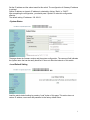
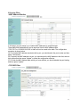
24 100FX + 2 Giga/SFP Combo Switch
BSF-2428MS
User Manual
1
Load Default Button
This button is located at the left panel of the switch. To make this button effective, press this
button for 3 seconds continuously. After completing the load default action, the entire switch
configuration will be restored to the factory default, including the IP configuration, the password
and the username.
◆Web Page
1 Administrator
• Authentication Configuration
The user name and password are case sensitive. In other words, “ADMIN” is not the same as
“admin”. The user can enter no more than 15 characters or numbers for user name and
password.
After changing the user name or password, you should press “Update” to make this configuration
effective.
The default setting: Username= admin; Password= system
• System IP Configuration
2
Set the IP address and the subnet mask for this switch. The configuration of Gateway IP address
is optional.
Statics IP address or dynamic IP address is selected by clicking “Static” or “DHCP”.
After completing the configuration, you should press “Update” to make this configuration
effective.
The default setting: IP address= 192.168.2.1
• System Status
The page shows the firmware version and the system configuration. The comment field indicates
the system name that can be easily identified. It does not affect the behavior of this switch.
• Load Default Setting
Load the switch default setting by pressing “Load” button of this page. This action does not
restore IP address, user name and password to the factory default value.
3
• Firmware Update
To execute the firmware update, you should enter the password at Password field and
ReConfirm field. After pressing “Update” button, the switch will flush the firmware and then
another page shows up to guide you to browse the binary file for update.
Once the binary file is selected, the update procedure will be completed in 40 seconds.
2 Port Management
• Port Configuration
The page can set the operating mode for multiple physical ports simultaneously, including the
network speed, duplex mode and flow control.
After you press” Update”, the actual operating mode of each port will be shown at the bottom left
side and the setting mode at the bottom right side.
4
• Port Mirroring
There are multiple “source ports” and “destination ports” that can be selected simultaneously.
The destination port means a port will snoop (or monitor) the packet coming from other ports.
The source port means a port that can generate a copy to the destination port.
4 options can be selected as the port mirroring methods:
(A) Disable: Disable port mirroring.
(B) Rx: The incoming packet of the source port will be copied to the destination port.
(C) Tx: The outgoing packet of the source port will be copied to the destination port.
(D) Tx & Rx: Packets at both directions will be copied to the destination port.
Please note that port mirroring function is bandwidth consuming. When multisource ports are
selected, the destination port may be congested.
Press “Update” to make it effective.
• Bandwidth Control
The bandwidth control is accomplished by entering a number to the “Tx rate” and “Rx rate” and
selecting “High speed” or “Low speed”. You can calculate the actual bandwidth by the following
formula. The rate values ranges from 1~255. “0” means the full wire speed.
5
Low:
(1) 32Kbps Tx/Rx bandwidth resolution for port 1~ port 26.
Actual Tx/Rx bandwidth =Rate value x 32 kbps. The rate value is 1~255.
High:
(1) 256Kbps Tx/Rx bandwidth resolution for port 1~ port 24.
Actual Tx/Rx bandwidth=Rate value x 256Kbps. The rate value is 1~255.
(2 ) the bandwidth resolution is 2048Kbps for port 25, port 26, .
Actual Tx/Rx bandwidth=Rate value x 2048Kbps. The rate value is 1~255.
• Broadcast Storm Control
Enter a number to set the threshold for broadcast storm control. The threshold is used to limit the
number of broadcast packets during a time unit. One time unit is 50us for Gigabit speed, 500 us
for 100Mbps speed and 5000us for 10Mbps speed.
You can enable the broadcast storm control for each port by clicking the port number. Clicking
“Update” makes the configuration effective.
3 VLAN Setting
• VLAN Mode
6
The procedure for configuring VLAN is lasted below:
(A) Select either Port based or tag based VLAN at web page of VLAN mode.
(B) If tag based VLAN is selected, you can select which port should be added/removed a tag.
(C) Select the uplink port for each VLAN. The usage of an uplink port is described in the following
section.
Note: Regarding the usage of VLAN uplink port, please refer to “Smart switch special function”.
• VLAN Member
You can set the VLAN member on this page. For Tag based VLAN, you should set the VLAN ID
VALN member for each group. There are 32 VLAN groups can be configured.
Press “Read” to show the VLAN setting. Press “Update” to make this configuration effective.
Press “Load Default” to clear the VLAN member selection.
• Multi-to-1 VLAN
This VLAN allow you to set VLAN without complicated configuration.
7
There are two limitations on this setting:
(A)The original setting of the VLAN group will be cleared and replaced by this special structure if
you enable this function. On the other hand, if you set the VLAN Group again, this special
structure will be cleared and replaced by your newest setting.
(B)This configuration is for port based VLAN only.
4 Per Port Counter
• Port Counter
There are 4 kinds of counter for each port; i.e.
(1) Tx packet & Rx packet counter;
(2) Collision & Tx packet counter;
(3) Dropped packet & Rx packet counter;
(4) CRC error & Rx packet counter.
You can select 1 of the 4 counters.
Click “Update” to select the counter. After clicking “Update”, the previous counter value for each
port will be flushed. Click “Clear” to clear the counter to “0”. Click “Refresh” to update the counter
value.
5 QoS Setting
• Priority Mode
8
There are 3 options for priority modes:
(A) First-In-First-Out: This setting makes all packets be treated as equal priority.
(B) All-high-before-low: This setting makes the switch forward the packet in high priority queue
continuously, until it is empty and then forward the low priority packet.
(C) Weight-and-round-Robin: This setting makes the switch forward the a specified number of
high priority packets and then a specified number of low priority packets. The switch repeats this
cycle continuously.
The “low weight” and “high weight” stands for the “number of packets in low priority queue” and
“number of packets in high priority queue” respectively.
The number is only valid for weight-and-round-robin mode.
Note: “0” is treated as “8” for both weight numbers.
• Port, 802.1p, IP/DS based
This page provides 3 types Class of Service:
(A) Port: The packet at this port will be unconditionally mapped as high priority.
(B) 802.1p: 802.1Q tag will be checked. The packet with tag precedence 4~7 and 0~3 will be
mapped to high priority and low priority respectively.
(C) IP/DS: The switch checks the TOS or DS field to decide the priority of the packet.
Note: If a packet hit any of 3 rules listed above, it will be treated as a high priority.
9
• TCP/UDP Port Based
This page provides Class of Service based on TCP/DUP protocol. In addition, this switch covers
a wide range of protocols. The mask number is used to define the protocol range. The result of
the calculation is a range of acceptable protocol number.
Example: The protocol should range from 1 ~ 65535 and the mask should be between 1 to 255.
If you fill 7549 to the protocol field and fill 13 to the mask field, you will get the actual protocol
numbers which can pass the switch. The calculation procedure is listed below.
(A) Transform the mask number into 1+4+8=13.
(B) Subtract 0, 1, 4, 8, 13 from 7549, you will get result of 7549, 7548, 7545, 7541, 7536.
(C) The protocol number listed above can pass the switch.
Selecting “Override” makes this page configuration override the port based, 802.1p based and
IP/DS based configuration.
There are 4 options for QoS setting:
F-I-F-O: The packet will be forwarded in first-in-first-out scheme.
Discard: The packet will be discarded at the source port.
High: The packet will be forwarded with the high priority.
Low: The packet will be forwarded with the Low priority.
Press “Update” to make this configuration effective.
10
6 Security Filter
• MAC Address Binding
In this page, you can assign up to 3 statics MAC addresses to a specified port.
These static MAC addresses will not be aged out from the MAC address table.
“ff ff ff ff ff ff” or “00 00 00 00 00 00” or blank will not be saved to the table. The configuration
procedure is shown below:
(A) To read the MAC address associated with a port, you should select the port number and then
press “read” button.
(B) To specify the MAC address to a port, you should enter the MAC address to the field, select a
port number and then press “Update” to make this configuration effective.
(C) To flush the MAC address table which you have defined, you should disable the port binding
and then press “Update”.
• TCP/UDP Filter
11
There are two types of protocol filter. The negative list defines the protocol that will be dropped.
The positive list defines the protocol that will be forwarded.
You should select 1 or more WAN ports to make this setting effective. The selected protocol will
be dropped at the secure WAN port.
Press “Update” to make the configuration effective.
7 Spanning Tree
• STP Bridge settings
STP Mode: Disable/STP/RSTP,
Bridge Priority: (0-61440),
Hello Time: 1-10 Sec,
Max Age : 6-40 Sec,
Forward delay : 4-30 Sec;
Enter a number to set, after completing the configuration, you should press “Submit” to make this
configuration effective
• STP Port settings
12
Port1-Port26, Priority: 0-240,
RPC: 1-200000000, 0=AUTO,
Enter a number to set, after completing the configuration, press “Submit” to make this
configuration effective
• Loopback Detection Settings
Loopback Detection Function: Disable/Enable,
Auto Wake Up: Disable/Enable,
Wake-Up Time Interval: 5/10/30/60Sec
After completing the configuration, press “Submit” to make this configuration effective
8 Trunking
• Link Aggregation settings
Select 1 of 4 hash algorithm for traffic distribution:
13
(1) Physical port ID;
(2) Source MAC address;
(3) Destination MAC address;
(4) Source MAC address & Destination MAC address. The port ID is selected by default setting.
Click more than one port for each trunk. If you select only one port for each trunk, this setting will
be ignored. Pressing “Submit” makes the configuration effective.
9 DHCP Relay Agent
• DHCP Relay Agent
DHCP Relay State: Disable/Enable,
DHCP Relay Hops Count Limit: 1-16,
DHCP Relay Option 82 State: Disable/Enable.
After completing the configuration, you should press “Update” to make this configuration effective
• Relay Server
Enter DHCP Server IP and press “Add” to make this configuration effective
14
• VLAN MAP Relay Agent
Enter VLAN ID: 1-4094, selecting Map Server IP,press “Add” to make this configuration effective
10 Backup/Recovery
This function provides a method for the user to backup/recover the switch configuration.
Press “Download” button to save the switch configuration to a file. This file contains the switch
configuration stored in EEPROM and will be saved in a readable text format.
Enter the file name or browse the directory to select a file which is used to restore the switch
configuration. Press “Update” to recover the switch configuration.
15
11 Miscellaneous Settings
• Output Aging Time
The output queue aging function allows the administrator to select the aging time of a packet
which is stored in the output queue for a long time. A packet stored in the output queue for a long
time will lower the free buffer, resulting in the poor utilization of the buffer and the poor switch
performance.
The aging time can be set within 200ms ~800ms or be disabled.
Note: Regarding the usage of output queue aging time, please refer to “Smart switch special
function”.
• VLAN Striding
When this function is enabled, the switch will directly forward a uni-cast packet to the destination
port. No matter if the destination port is in the same VLAN group.
• IGMP Snooping
This function enable or disable the IGMP snooping. Only V1 & V2 are supported by this setting.
16
12 SNMP Settings
Enter Community Name, selecting
makes the configuration effective.
Access Right: Read only/ Read/Write. Pressing “Update”
SNMP Settings: Enter System Description/ System Contact/ System Location info. Pressing
“Update” makes the configuration effective.
SNMP Trap Settings: Trap State selecting Disable /Enable. Pressing “Update” makes the
configuration effective.
13 Logout
Pressing “Accept”, System logs out, pressing “Back” System turns back
17