1
12/16 Bays
Fibre/SAS/iSCSI to
SAS RAID Subsystem
Manual
Version 1.0
www.raiddeluxe.com
RAID Subsystem
Fibre/SAS/iSCSI to 6Gb/s SAS
RAID Subsystem
USER Manual
Version: 1.0
Issue Date: December 2010
Copyright and Trademarks
The information of the products in this manual is subject to change
without prior notice and does not represent a commitment on the part
of the vendor, who assumes no liability or responsibility for any errors
that may appear in this manual. All brands and trademarks are the
properties of their respective owners. This manual contains materials
protected under International Copyright Conventions. All rights
reserved. No part of this manual may be reproduced in any form or by
any means, electronic or mechanical, including photocopying, without
the written permission of the manufacturer and the author.
FCC Statement
This equipment has been tested and found to comply with the limits for a Class A digital device, pursuant to part 15 of the FCC Rules.
These limits are designed to provide reasonable protection against interference in a residential installation. This equipment generates, uses,
and can radiate radio frequency energy and, if not installed and used
in accordance with the instructions, may cause harmful interference to
radio communications. However, there is no guarantee that interference will not occur in a particular installation.
Manufacturer’s Declaration for CE Certification
We confirm RDL series 12/16-bays 6Gb/s SAS RAID subsystem have
been tested and found comply with the requirements set up in the
council directive on the approximation of the low of member state relating to the EMC Directive2004/108/EC. For the evaluation regarding
to the electromag-netic compatibility, the following standards where
applied:
EN 55022: 2006, Class A
EN 61000-3-2: 2006
EN 61000-3-3: 1995+A1: 2001+A2: 2005
EN 55024:1998+A1:2001=A2:2003
IEC61000-4-2: 2001
IEC61000-4-3: 2006
IEC61000-4-4: 2004
IEC61000-4-5: 2005
IEC61000-4-6: 2006
IEC61000-4-8: 2001
IEC61000-4-11: 2004
Contents
1. Introduction............................................................... 12
1.1 Overview......................................................................... 12
1.2 Features.......................................................................... 14
1.3 Locations of the Subsystem Component............................... 19
1.3.1 SAS RAID Subsystem Front View.................................... 19
1.3.2 SAS RAID Subsystem Rear View..................................... 20
1.3.2.1 Rear View of Fibre to SAS RAID Controller................... 21
1.3.2.2 Rear View of SAS to SAS RAID Controller.................... 21
1.3.2.3 Rear View of iSCSI to SAS RAID Controller.................. 22
1.3.2.4 Expander Output..................................................... 22
1.3.2.5 Global Status.......................................................... 23
1.3.2.6 Power Supply/Cooling Fan LED ................................. 23
1.4 SAS RAID Subsystem Alarm............................................... 24
1.5 Expansion Connection........................................................ 25
2. Hardware Installation................................................ 27
2.1 Installing an Subsystem into the Rack or Tower (Optional)...... 28
2.2 Installing or Removing SAS/SATA Drives in the Subsystem..... 29
2.2.1 Installing SAS/SATA Drives in the Enclosure..................... 30
2.2.2 Installing SATA Drives with Interposer Board.................... 31
2.2.3 Removing Drives from the Enclosure............................... 34
2.3 Installing or Removing the SAS Series RAID Controller in the
Subsystem............................................................................ 34
2.3.1 Installing the SAS RAID Controller in the Subsystem......... 34
2.3.2 Removing the SAS RAID Controller from the Subsystem.... 35
2.3.3 Check Controller Memory Module.................................... 36
2.3.3.1 Installing the DDR-2 SDRAM DIMM............................ 36
2.3.3.2 Removing the DDR-2 SDRAM DIMM............................ 37
2.3.4 Adding a Battery Backup Module (Option)........................ 37
2.4 Installing and Removing the Power Supply/Cooling Fan Modules.
.......................................................................................... 37
2.4.1 Installing the Power Supply/Cooling Fan Modules.............. 37
2.4.2 Removing a Power Supply/Cooling Fan Modules................ 38
2.5 Installing the Power Cord Clamp ........................................ 38
2.6 Connecting the RAID Subsystem ........................................ 40
2.6.1 Connecting to Host System ........................................... 40
2.6.2 Connecting Monitor Port................................................ 40
2.7 Configuring RAID Subsystems............................................. 42
2.6.3 Power Up the RAID Subsystem . .................................... 42
2.7.1 Configuring Method...................................................... 43
2.7.2 Format, Partition and Mount the SAS RAID Subsystem Volumes.................................................................................. 44
3. Configuration Methods............................................... 45
3.1 Using Local Front Panel Touch-control Keypad....................... 45
3.2 VT100 Terminal (Using the controller’s serial port)................. 47
3.2.1 RAID Subsystem RS-232C Port Pin Assignment................ 47
3.2.2 Start-up VT100 Screen.................................................. 48
3.3 Web Browser-based RAID Manager...................................... 51
3.4 Configuration Menu Tree.................................................... 51
4. LCD Configuration Menu............................................. 53
4.1 Starting LCD Configuration Utility....................................... 53
4.2 LCD Configuration Utility Main Menu Options......................... 54
4.3 Configuring Raid Sets and Volume Sets................................ 54
4.4 Designating Drives as Hot Spares........................................ 55
4.5 Using Easy RAID Configuration .......................................... 55
4.6 Using Raid Set and Volume Set Functions ............................ 57
4.7 Navigation Map of the LCD ................................................ 58
4.7.1 Quick Volume And Raid Setup........................................ 59
4.7.2 Raid Set Functions........................................................ 59
4.7.2.1 Create A New Raid Set ............................................ 60
4.7.2.2 Delete Raid Set....................................................... 60
4.7.2.3 Expand Raid Set...................................................... 61
4.7.2.4 Offline Raid Set....................................................... 61
4.7.2.5 Activate Incomplete RaidSet...................................... 62
4.7.2.6 Create Hot Spare Disk.............................................. 62
4.7.2.7 Delete Hot Spare Disk.............................................. 62
4.7.2.8 Display Raid Set Information..................................... 62
4.7.3 Volume Set Functions................................................... 63
4.7.3.1 Create Raid Volume Set ........................................... 64
4.7.3.1.1 Volume Name...................................................... 64
4.7.3.1.2 Raid Level .......................................................... 64
4.7.3.1.3 Stripe Size.......................................................... 64
4.7.3.1.4 Cache Mode........................................................ 65
4.7.3.1.5 SAS Port/SAS LUN Base/SAS LUN.......................... 65
4.7.3.1.6 Tagged Queuing................................................... 66
4.7.3.1.7 Initialization Mode................................................ 66
4.7.3.2 Delete Existed Volume Set........................................ 66
4.7.3.3 Modify Volume Set Attribute...................................... 66
4.7.3.3.1 Volume Set Migration........................................... 67
4.7.3.4 Check Volume Set Consistency.................................. 68
4.7.3.5 Stop Volume Set Consistency Check........................... 68
4.7.3.6 Display Volume Set Information................................. 68
4.7.4 Physical Drive Functions ............................................... 68
4.7.4.1 Display Drive Information ........................................ 70
4.7.4.2 Create Pass-Through Disk ........................................ 70
4.7.4.3 Modify Pass-Through Disk ........................................ 70
4.7.4.4 Delete Pass-Through Disk......................................... 71
4.7.4.5 Identify The Selected Drive....................................... 71
4.7.5 Raid System Functions.................................................. 71
4.7.5.1 Mute The Alert Beeper . ........................................... 73
4.7.5.2 Alert Beeper Setting . .............................................. 73
4.7.5.3 Change Password.................................................... 73
4.7.5.4 JBOD/RAID Mode Configuration................................. 73
4.7.5.5 Raid Rebuild Priority................................................. 74
4.7.5.6 SATA NCQ Mode Support.......................................... 74
4.7.5.7 HDD Read Ahead Cache............................................ 74
4.7.5.8 Volume Data Read Ahead.......................................... 74
4.7.5.9 Disk Write Cache HDD.............................................. 75
4.7.5.10 Disk Capacity Truncation Mode................................ 75
4.7.5.11 Restart Controller.................................................. 75
4.7.6 Hdd Power Management................................................ 76
4.7.6.1 Stagger Power On Control......................................... 76
4.7.6.2 Time to Hdd Low Power Idle...................................... 76
4.7.6.3 Time To Hdd Low RPM Mode...................................... 77
4.7.6.4 Time To Spin Down Idle HDD . ................................. 77
4.7.7 In Band SAS Config...................................................... 77
4.7.7.1 InBand SAS Function............................................... 77
4.7.7.2 InBand SAS Port...................................................... 78
4.7.8 Ethernet Configuration.................................................. 78
4.7.8.1 DHCP..................................................................... 78
4.7.8.2 Local IP Adress........................................................ 78
4.7.8.3 HTTP Port Number................................................... 79
4.7.8.4 Telnet Port Number.................................................. 79
4.7.8.5 SMTP Port Number................................................... 79
4.7.8.6 Ethernet Address..................................................... 80
4.7.9 Show System Events.................................................... 80
4.7.10 Clear all Event Buffers................................................. 80
4.7.11 Hardware Monitor Information...................................... 80
4.7.12 System Information.................................................... 80
5. VT-100 Utility Configuration ...................................... 82
5.1 Configuring Raid Sets/Volume Sets...................................... 82
5.2 Designating Drives as Hot Spares........................................ 83
5.3 Using Quick Volume /Raid Setup Configuration...................... 83
5.4 Using Raid Set/Volume Set Function Method......................... 85
5.5 Main Menu ...................................................................... 86
5.5.1 Quick Volume/Raid Setup.............................................. 87
5.5.2 Raid Set Function......................................................... 91
5.5.2.1 Create Raid Set ...................................................... 91
5.5.2.2 Delete Raid Set....................................................... 93
5.5.2.3 Expand Raid Set...................................................... 93
5.5.2.4 Offline Raid Set....................................................... 95
5.5.2.5 Activate Raid Set..................................................... 95
5.5.2.6 Create Hot Spare..................................................... 96
5.5.2.7 Delete Hot Spare..................................................... 96
5.5.2.8 Raid Set Information................................................ 97
5.5.3 Volume Set Function..................................................... 97
5.5.3.1 Create Volume Set (0/1/10/3/5/6)............................. 98
5.5.3.1.1 Volume Name.................................................... 100
5.5.3.1.2 Raid Level......................................................... 100
5.5.3.1.3 Capacity........................................................... 101
5.5.3.1.4 Stripe Size........................................................ 102
5.5.3.1.5 SAS Port #/ Fibre Host # ................................... 103
5.5.3.1.6 SAS LUN Base/Fibre LUN Base/iSCSI Target Node.. 104
5.5.3.1.7 SAS LUN/Fibre LUN/iSCSI LUN............................. 105
5.5.3.1.8 Cache Mode...................................................... 106
5.5.3.1.9 Tag Queuing...................................................... 107
5.5.3.2 Create Raid30/50/60.............................................. 108
5.5.3.3 Delete Volume Set................................................. 108
5.5.3.4 Modify Volume Set................................................. 109
5.5.3.4.1 Volume Growth.................................................. 110
5.5.3.4.2 Volume Set Migration......................................... 111
5.5.3.5 Check Volume Set.................................................. 111
5.5.3.6 Stop Volume Set Check.......................................... 111
5.5.3.7 Display Volume Set Info......................................... 112
5.5.4 Physical Drives........................................................... 112
5.5.4.1 View Drive Information . ........................................ 113
5.5.4.2 Create Pass-Through Disk....................................... 113
5.5.4.3 Modify Pass-Through Disk....................................... 114
5.5.4.4 Delete Pass-Through Disk....................................... 114
5.5.4.5 Identify Selected Drive........................................... 115
5.5.4.6 Identify Subsystem................................................ 115
5.5.5 Raid System Function................................................. 116
5.5.5.1 Mute The Alert Beeper . ......................................... 116
5.5.5.2 Alert Beeper Setting............................................... 117
5.5.5.3 Change Password.................................................. 118
5.5.5.4 JBOD/RAID Function.............................................. 118
5.5.5.5 Background Task Priority........................................ 119
5.5.5.6 SATA NCQ Support................................................. 120
5.5.5.7 HDD Read Ahead Cache.......................................... 120
5.5.5.8 Volume Data Read Ahead........................................ 121
5.5.5.9 Disk Write Cache Mode........................................... 121
5.5.5.10 Auto Activate Raid Set.......................................... 122
5.5.5.11 Capacity Truncation . ........................................... 122
5.5.5.12 Update Firmware................................................. 123
5.5.5.13 Restart Controller................................................ 124
5.5.6 Hdd Power Management.............................................. 124
5.5.6.1 Stagger Power On Control....................................... 125
5.5.6.2 Time to Hdd Low Power Idle.................................... 126
5.5.6.3 Time To Hdd Low RPM Mode.................................... 126
5.5.6.4 Time To Spin Down Idle HDD . ............................... 127
5.5.7 In Band SAS Config.................................................... 128
5.5.7.1 InBand SAS Function............................................. 128
5.5.7.2 InBand SAS Port.................................................... 129
5.5.8 Ethernet Configuration ............................................... 130
5.5.8.1 DHCP Function...................................................... 130
5.5.8.2 Local IP Address.................................................... 131
5.5.8.3 HTTP Port Number................................................. 132
5.5.8.4 Telnet Port Number................................................ 133
5.5.8.5 SMTP Port Number................................................. 133
5.5.8.6 Ethernet Address................................................... 134
5.5.9 View System Events................................................... 134
5.5.10 Clear Events Buffer................................................... 135
5.5.11 Hardware Monitor Information.................................... 135
5.5.12 System Information.................................................. 135
6. Web Browser-based Configuration .......................... 137
6.1 Firmware-embedded TCP/IP & web browser-based RAID manager (using the controller’s 10/100/1000 LAN port)................... 137
6.2 Web Browser Start-up Screen .......................................... 138
6.3 Main Menu .................................................................... 139
6.4 Quick Function................................................................ 139
6.5 Raid Set Functions.......................................................... 140
6.5.1 Create a New Raid Set ............................................... 140
6.5.2 Delete Raid Set.......................................................... 141
6.5.3 Expand Raid Set......................................................... 141
6.5.4 Offline Raid Set.......................................................... 142
6.5.5 Rename Raid Set........................................................ 143
6.5.6 Activate Incomplete Raid Set....................................... 143
6.5.7 Create Hot Spare....................................................... 144
6.5.8 Delete Hot Spare........................................................ 144
6.5.9 Rescue Raid Set......................................................... 145
6.6 Volume Set Functions...................................................... 145
6.6.1 Create Volume Set (0/1/10/3/5/6) . ............................. 146
6.6.2 Create Raid30/50/60 (Volume Set 30/50/60)................. 149
6.6.3 Delete Volume Set...................................................... 149
6.6.4 Modify Volume Set...................................................... 150
6.6.4.1 Volume Growth..................................................... 151
6.6.4.2 Volume Set Migration............................................. 151
6.6.5 Check Volume Set...................................................... 152
6.6.6 Schedule Volume Check.............................................. 153
6.6.7 Stop Volume Check..................................................... 153
6.7 Physical Drive ................................................................ 153
6.7.1 Create Pass-Through Disk............................................ 154
6.7.2 Modify a Pass-Through Disk......................................... 154
6.7.3 Delete Pass-Through Disk............................................ 155
6.7.4 Identify Enclosure...................................................... 155
6.8 System Controls............................................................. 156
6.8.1 System Config........................................................... 156
• System Beeper Setting................................................... 157
• Background Task Priority................................................. 157
• JBOD/RAID Configuration................................................ 157
• SATA NCQ Support......................................................... 157
• HDD Read Ahead Cache.................................................. 157
• Volume Data Read Ahead................................................ 157
• HDD Queue Depth . ....................................................... 158
• Spin Down Idle HDD (Minutes)......................................... 158
• Disk Write Cache Mode................................................... 158
• Disk Capacity Truncation Mode......................................... 158
6.8.2 Hdd Power Management.............................................. 159
6.8.2.1 Stagger Power On Control....................................... 159
6.8.2.2 Time to Hdd Low Power Idle ................................... 160
6.8.2.3 Time To Hdd Low RPM Mode ................................... 160
6.8.2.4 Time To Spin Down Idle HDD . ............................... 160
6.8.3 Fibre Channel Config................................................... 160
6.8.3.1 View Error Statistics............................................... 162
6.8.3.2 View/Edit Host Name List........................................ 162
6.8.3.3 View/Edit Volume Set Host Filters............................ 163
6.8.4 iSCSI Configuration.................................................... 165
6.8.5 Ethernet Configuration ............................................... 167
6.8.6 Alert By Mail Configuration ........................................ 168
6.8.7 SNMP Configuration.................................................... 169
• SNMP Trap Configurations............................................... 169
• SNMP System Configurations........................................... 169
• SNMP Trap Notification Configurations............................... 170
6.8.8 NTP Configuration ..................................................... 170
• Time Zone..................................................................... 170
• Automatic Daylight Saving.............................................. 171
6.8.9 View Events/Mute Beeper............................................ 171
6.8.10 Generate Test Event.................................................. 171
6.8.11 Clear Events Buffer................................................... 172
6.8.12 Modify Password....................................................... 172
6.8.13 Update Firmware ..................................................... 173
6.8.14 Restart Controller .................................................... 173
6.9 Information.................................................................... 174
6.9.1 Raid Set Hierarchy...................................................... 174
6.9.2 System Information.................................................... 174
6.9.3 Hardware Monitor....................................................... 175
7. Assigning Volume to Dual Controllers....................... 176
7.1 Dual Independent Mode .................................................. 177
7.1.1 Mapping a Volume to the Host LUNs.............................. 177
7.2 Dual Redundant Mode...................................................... 178
7.2.1 Mapping a Volume to the Host LUNs.............................. 178
7.2.2 Active-to-Active Configuration...................................... 179
7.2.3 Active-to-Standby Configuration................................... 179
7.3 Forcing Controller Failover for Testing................................ 179
7.3.1 Pulling out one of the controllers from the carrier........... 179
7.3.2 Manual switchover request.......................................... 180
Appendix A................................................................... 181
Upgrading Flash ROM Update Process...................................... 181
Establishing the Connection for the RS-232.............................. 181
Upgrade Firmware Through ANSI/VT-100 Terminal Emulation..... 182
Upgrade Firmware Through Web Browser Manager (LAN Port).... 185
Appendix B................................................................... 186
Battery Backup Module (ARC8006-2)...................................... 186
BBM Connector and Components........................................ 186
Battery Pack Outlines........................................................ 186
Status of BBM.................................................................. 187
Appendix C................................................................... 190
SNMP Operation & Definition.................................................. 190
Appendix D................................................................... 192
Event Notification Configurations.......................................... 192
A. Device Event................................................................ 192
B. Volume Event............................................................... 193
C. RAID Set Event............................................................ 194
D. Hardware Monitor Event................................................ 194
Appendix E................................................................... 196
RAID Concept...................................................................... 196
RAID Set........................................................................... 196
Volume Set........................................................................ 196
Easy of Use Features........................................................... 197
• Instant Availability/Background ....................................... 197
• Online Array Roaming/Offline RAID set.............................. 197
• Online Capacity Expansion............................................... 197
• Online RAID Level and Stripe Size Migration...................... 198
High availability.................................................................. 199
• Creating Hot Spares...................................................... 199
• Hot-Swap Disk Drive Support.......................................... 199
• Hot-Swap Disk Rebuild................................................... 200
Understanding RAID........................................................... 200
• RAID 0........................................................................ 201
• RAID 1........................................................................ 201
• RAID 10(1E)................................................................. 202
• RAID 3........................................................................ 202
• RAID 5........................................................................ 203
• RAID 6........................................................................ 203
• RAID x0....................................................................... 204
• JBOD........................................................................... 205
• Single Disk (Pass-Through Disk)...................................... 205
INTRODUCTION
1. Introduction
This section presents a brief overview of the 12/16 bays external Fibre/SAS/iSCSI to 6Gb/s SAS RAID subsystem.
1.1 Overview
SAS 2.0 builds on parallel SCSI by providing higher performance,
improving data availability, and simplifying system design. The SAS
2.0 interface supports both 6Gb/s SAS disk drives for data-intensive applications and 6Gb/s Serial ATA (SATA) drives for low-cost
bulk storage of reference data. The Fibre/SAS/iSCSI to 6Gb/s SAS
RAID controllers attach directly to SATA/SAS midplanes with 3 x
Z-PACK HM-Zd high speed connectors or increase capacity using
one additional SFF-8088 external connector. When used with SAS
expanders, the controller can provide up to (122) devices through
one or more SAS JBODs, making it an ideal solution for enterpriseclass storage applications that called for maximum configuration
flexibility.
The Fibre/SAS/iSCSI to 6Gb/s SAS RAID subsystem provides three
kinds of host interface link to the host board on the server system. This subsystem utilizes the same RAID kernel that has been
field-proven in existing internal/external SATA/SAS RAID controller
products, allowing to bring stable and reliable SAS RAID external
subsystem.
The Fibre/SAS/iSCSI to 6Gb/s SAS RAID subsystem provides a
2-U/3-U rack-mounted external storage chassis capable of accommodating up to 12/16 6.0-Gb/s, Serial-Attached SCSI (SAS) drives
or 6.0-Gb/s Serial ATA (SATA) drives. The redundant controller
model provides fault-tolerant links across separate host interface,
while the single controller model provides a single, straight-through
data path.
Unparalleled Performance
The high speed host interfaces make Fibre/SAS/iSCSI to 6Gb/s
SAS RAID subsystem well suited for professionals who need large
capacity and exceptional performance with connectivity. The Fibre/
12
INTRODUCTION
SAS/iSCSI to 6Gb/s SAS RAID subsystem incorporates onboard
high performance 800MHz RAID-on-Chip storage processor and
DDR2-800 SDRAM memory to deliver true hardware RAID. The
subsystem each includes one DIMM socket with default 1GB of ECC
DDR2-800 register SDRAM with optional battery backup module,
upgrade to 4GB using x8 or x16 devices. The test result is against
overall performance compared to other external SAS RAID subsystems. Applications demand for higher computing power, networking
bandwidth and support for virtualization applications are driving
RAID subsystem for improved architecture internal bus interface
and RAID performance. The powerful new ROC processors integrated 16 x 6Gb/s SAS ports on chip delivers high performance for
NAS, server RAID solutions, supercomputing, near-line backup,
security systems, streaming and cloud computing applications.
Unsurpassed Data Availability
Designed and leveraged with Areca’s existing high performance
solution, this controller delivers high-capacity at the best of cost/
performance value. It supports the hardware RAID 6 engine to allow two HDDs failures without impact the existing data and performance. Its high data availability and protection derives from the
many advanced RAID features.
The Fibre/SAS/iSCSI to SAS RAID subsystems allows easy scalability from JBOD to RAID. It can be configured to RAID levels 0,
1, 1E, 3, 5, 6, 10, 30, 50, 60, Single Disk or JBOD. With innovative
new RAID-on-Chip 6Gb/s SAS feature and support for SATA, SAS
and SSDs, the Fibre/SAS/iSCSI to SAS RAID subsystems provides
small- to mid-sized enterprises with superior levels of RAID performance and scalability for external storage. Using cost-effective
SATA disk drive and completely integrated high-performance and
data-protection capabilities, it can meet the performance and features of a midrange storage product at an entry-level price.
Easy RAID Management
Configuration and monitoring can be managed either through the
LCD control panel, RS232 port or Ethernet port. The firmware also
contains an embedded terminal emulation via the RS-232 port.
The firmware-embedded web browser-based RAID manager allows
13
INTRODUCTION
local or remote to access it from any standard internet browser via
a 1Gb/s LAN port. The firmware contains SMTP manager monitors
all system events and user can select either single or multiple user
notifications to be sent via "Plain English" e-mails. The firmwareembedded SNMP agent allows remote to monitor events via LAN
with no SNMP agent required. The controller also supports API
library for customer to write its own monitor utility.
The controller also supports API library for customer to write its
own monitor utility. The Single Admin Portal (SAP) monitor utility
can support one application to manage multiple RAID units in
the network. The Disk Stress Test (DST) utility kicks out disks
meeting marginal spec before the RAID unit is actually put on-line
for real business. The hardware monitor can monitor subsystem
environment and show the warning message.
1.2 Features
Adapter Architecture
• 800 MHz PowerPC RAID-on-Chip for RAID core and SAS
microcode
• Up to 4GB DDR2-800 register SDRAM on one DIMM socket with
ECC protection using x8 or x16 devices
• NVRAM for RAID event log & transaction log
• Write-through or write-back cache support
• Redundant flash image for adapter availability
• Real time clock support
• Battery Backup Module ready (Option)
• Management port seamless take-over
RAID Features
• RAID level 0, 1, 1E, 3, 5, 6, 10, 30, 50, 60, Single Disk or JBOD
• Multiple RAID selection
• Online array roaming
• Offline RAID set
• Online RAID level/stripe size migration
• Online capacity expansion and RAID level migration simultaneously
• Online volume set growth
• Support global hot spare and dedicated hot spare
• Instant availability and background initialization
14
INTRODUCTION
•
•
•
•
Automatic drive insertion / removal detection and rebuilding
Greater than 2TB per volume set (64-bit LBA support)
Greater than 2TB per disk drive
Disk scrubbing/ array verify scheduling for automatic repair of
all configured RAID sets
• Login record in the event log with IP address and service (http,
telnet and serial)
• Support intelligent power management to save energy and extend service life
• Support NTP protocol to synchronize RAID controller clock over
the on-board LAN port
• Redundant controller operation with active/active and failover/
failback function
• Dual-active RAID controller with cache mirroring through dedicated high speed bus
• Automatic synchronization of firmware version in the dual-active
mode
• Multi-path & load-balancing support (Microsoft MPIO)
• Max 122 devices
• Max 128 LUNs (volume set) per controller
Monitors/Notification
• LCD Control Panel for setup, alarm mute and configuration
• System status indication through LCD, LED and alarm buzzer
• Subsystem management ready
Drive Interface
• Up to 122 devices using SAS expanders (one external Min SAS
4x connector)
• Up to 6Gb/s per port
Host Interface
• 8Gb Fibre-to-SAS
Four 8Gb/s Fibre Channels - 800MB/sec per channel
• 6Gb SAS-to-SAS
Two Min SAS 4x 6Gb/s SAS Ports - 600MB/sec per PHY link
• 1Gb iSCSI-to-SAS
Four 1Gb/s Ethernet Channel - Full iSCSI offload (complete
ULP, TCP offload )
RAID Management
• Field-upgradeable firmware in flash ROM
15
INTRODUCTION
• Firmware-embedded manager via RS-232 port
• Firmware-embedded web browser-based RAID manageraccess your RAID subsystem from any standard internet browser via 10/100/1000 LAN port
• Firmware-embedded SMTP manager monitors all system events
and user can select either single or multiple user notifications to
be sent via “Plain English” e-mails
• Firmware-embedded SNMP agent allows remote to monitor
events via 10/100/1000 LAN with no SNMP agent required
• Access terminal menu by telnet via 10/100/1000 LAN port
• API library for customer to write its own monitor utility
• SAP management utility to easily manage multiple RAID units
in the network
Software Drivers
• OS Independent
Physical/Electrical
SAS hard drives
• Up to 12/16 2.5-inch or 2.5-inch SAS hot-plug hard drives (6.0
Gb/s) at speeds of 10K or 15K rpm
SATA hard drives
• Up to 12/16 2.5-inch or 3.5-inchSATA hot-plug hard drives (6.0
Gb/s) at speeds of 7.2K or 10K rpm. Connectivity to the controller
system backplane is provided through an interposer assembly for
redundant controller.
Subsystem Controller Modules
• Controller board
1 or 2 modules
• Sensors
2 sensor per controller Board
Backplane Board
Connectors
• 12/16 SAS hard-drive connectors
• 2 power supply/cooling fan module connectors
• 2 sets of controller board connectors (3 connectors each controller board)
Sensors
• 12/16 temperature sensors (one for each slot)
16
INTRODUCTION
Controller Back-Panel Connectors
Host connectors (per controller board)
• 2 SAS CH0 and CH1 connector for connection to the host
• 4 Fibre CH0, CH1, CH2 and CH3 connector for connection to the
host
• 4 iSCSI CH0, CH1, CH2 and CH3 connector for connection to the
host
Expander connector (per controller board)
• 2 SAS “EXP 0 & EXP 1” connector for expansion to an additional
SAS JBOD enclosure
Management connector (per controller board)
• 2 6-pin UART RJ-11 connector
• 1 LAN RJ-45 connector
• 2 SAS CH0&CH1 connector for SAS to SAS RAID controller
LED Indicators
Hard-drive carrier
• 1 single-color activity LED status indicator
• 1 two-color fault/power LED status indicator
Controller board
• 2 single-color LED status indicators for each SAS expander port,
one for link and one for the activity status
Host board
• 2 single-color LED status indicator per SAS host
• 2 single-color LED status indicator per Fibre host
• 2 single-color LED status indicators per iSCSI host
Power supply/cooling fan module
• 2 single-color LED status indicators for AC_OK and FAULT on
each power supply/cooling fan module
Power Supplies
Dual hot swap and redundant with PFC, N+1 design
• Wattage
595 W maximum continuous;
• Voltage
100–240 V rated
• Frequency
50–60 Hz
• Amperage (Max)
6.18A (120 VAC), 3.23A (230 VAC)
17
INTRODUCTION
Dimensions
2U 12 bays 19-inch rackmount chassis
• Without handles
88.2(H) x 445(W) x 506(D)mm
• With handles
88.2(H) x 482(W) x 542(D)mm
3U 16 bays 19-inch rackmount chassis
• Without handles
88.2(H) x 445(W) x 506(D)mm
• With handles
88.2(H) x 482(W) x 542(D)mm
Subsystem Net Weight (Without Drives)
• Single 12/16 bays
16.5 kg/20.7 kg
• Dual 12/16 bays
17.5 kg/21.7 kg
Environmental
Temperature:
• Operating
• Storage
0° to 40°C
–40° to 60°C
Relative humidity:
• Operating
• Storage
10% to 80% (non-condensing)
5% to 95% (non-condensing)
Subsystem Naming Rule
18
INTRODUCTION
1.3 Locations of the Subsystem Component
The main components of the Fibre/SAS/iSCSI to 6Gb/s SAS RAID
subsystem are shown in the below figure.
1.3.1 SAS RAID Subsystem Front View
● 2U-12 bays SAS RAID Subsystem Front View
● 3U-16 bays SAS RAID Subsystem Front View
● Disk Slot Numbers
To perform a disk hot-plug procedure, you must know the physical disk slot number for the drive that you want to install or remove. The number on the drive tray shows how RAID subsystem
disk slots are numbered. Disk slot number is reflected in the RAID
manager interface.
● Drive Tray LED Indicators
Each drive tray in your subsystem has two LEDs: an activity LED
(blue) and one power/fault (two colors green/red) status LED.
The activity LED flashes whenever the drive is accessed. The
following table describes the Fibre/SAS/iSCSI to 6Gb/s SAS RAID
subsystem drive tray LED status.
19
INTRODUCTION
LED
Normal status
Problem Indication
Blue LED
(Activity)
When the activity LED
is illuminated, there is
I/O activity on that disk
drive. When the LED is
dark; there is no activity
on that disk drive.
N/A
Green/Red LED
(Power/Fault)
When the power LED
(green) is solid illuminated and fault LED (red)
is off, that disk is present
and status normal.
When the fault LED is
solid illuminated there is
no disk present.
When the fault LED (red) is slow
blinking (2 times/sec), that disk
drive has failed and should be
hot-swapped immediately.
When the activity LED (blue) is
illuminated and fault LED (red)
is fast blinking (10 times/sec)
there is rebuilding activity on
that disk drive.
1.3.2 SAS RAID Subsystem Rear View
● 2U-12 bays SAS RAID Subsystem Rear View
● 3U-16 bays SAS RAID Subsystem Rear View
20
INTRODUCTION
1.3.2.1 Rear View of Fibre to SAS RAID Controller
The following table describes the Fibre to 6Gb/s SAS RAID subsystem host channel link/activity LED.
Fibre Host Port LED
Status
Link LED
(Green light)
When link LED is illuminated light that indicates the
Fibre channel host link has connected.
Activity LED
(Blue light)
The Fibre channel host accesses to the Fibre to SAS
RAID subsystem.
1.3.2.2 Rear View of SAS to SAS RAID Controller
The following table describes the SAS to 6Gb/s SAS RAID subsystem host channel link/access LED.
SAS Host Port LED
Status
Link LED
(Green light)
When host port link LED is illuminated for 1 second and
turns off for 3 seconds that indicates the one link has
connected.
When host port Link LED is illuminated for 2 seconds
and turns off for 2 seconds that indicates the two links
have connected.
When host port Link LED is illuminated for 4 seconds
that indicates the four links have connected.
Access LED
(Blue light)
When access LED is illuminated that indicates the SAS
host accesses to the SAS to SAS RAID subsystem.
21
INTRODUCTION
1.3.2.3 Rear View of iSCSI to SAS RAID Controller
The following table describes the iSCSI to 6Gb/s SAS RAID
subsystem host channel link/activity and speed LED.
iSCSI Host
Port
Status
Link/Activity LED
(Green light)
When Link/Activity LED is flashed that indicates the
iSCSI host link has connected. When Link/Activity LED is
illuminated that indicates the iSCSI host accesses to the
iSCSI RAID subsystem.
Speed LED
(Green light)
When speed LED is illuminated that indicates the iSCSI
host speed is runing at 1.0Gb/s mode. When Speed LED
off that indicates the iSCSI host speed is runing at 10/100
Mb/s mode.
1.3.2.4 Expander Output
The following table describes the Fibre/SAS/iSCSI to SAS RAID
subsystem expander port link/access LED.
Expander
LED
22
Status
Link LED
(Green light)
When link LED is illuminated for 1 second and turns off for 3
seconds that indicates the one expander link has connected.
When Link LED is illuminated for 2 seconds and turns off
for 2 seconds that indicates the two expander links have
connected.
When Link LED is illuminated for 4 seconds that indicates the
four expander links have connected.
Access LED
(Blue light)
When access LED is illuminated that indicates the SAS expander connector accesses to next JBOD.
HARDWARE INSTALLATION
1.3.2.5 Global Status
On the left side of RS232 port are two LEDs which indicate the
status of the RAID controller working on redundant mode.
Subsystem Indicators
Status
Power LED (Heartbeat/Green light)
When power LED is illuminated that indicates the subsystem in working state. Flashing power LED indicates
controller CPU access the subsystem resource.
Fault LED
(Red light)
Flashing fault LED indicates a controller reset occurs on
a controller.
1.3.2.6 Power Supply/Cooling Fan LED
The enclosure supports two separate power modules. Each of
them contains an integrated power supply and two cooling fans.
The LEDs on the JBOD enclosure’s power supplies indicate
status of the power supply: one for AC_OK (green) and other
FAULT(red). The following figure is shown LEDs on the power
supply module.
23
HARDWARE INSTALLATION
The following table describes the power LEDs status.
Power LED Status
Indication
AC_OK (Green LED)
The AC_OK LED indicates that the AC line is present and
above the minimum AC input voltage threshold
FAULT (Red LED)
The FAULT LED is driven by the microprocessor and will
indicate that a power supply fault has occurred
The power supply cooling shall be provided by the internal tandem
fans, powered by the common 12V rail voltage. Fan speed is controlled by PWM input signal. And the power supply firmware shall
determine the fan RPM required to provide forced air cooling using
data from a thermal sensor in the power supply that reflects the
output loading.
The cooling fans included on the power supply run on separate control circuits from the power supply. Therefore, if one power supply
fails, the failed power’s fan continues to work on the power supplied from the other good power supply.
Note:
A power supply/cooling fan module can be removed from a
powered-on enclosure; however, the expander controller may
automatically shut down the enclosure if overheating occurs.
1.4 SAS RAID Subsystem Alarm
An audible alarm is activated if any of the fault conditions occur,
such as Voltage, Temperature, Fan, Power Supply or from SES2.
The “Alert Beeper Setting” function on the RAID System Function
is used to disable or enable the RAID subsystem alarm tone
generator. The “Mute The Alert Beeper” function on the "RAID
System Function" is used to control the Fibre/SAS/iSCSI to 6Gb/s
SAS RAID subsystem beeper. It turns the beeper off temporarily.
The beeper will still activate on the next event.
24
HARDWARE INSTALLATION
Note:
It is rare for both Fibre/SAS/iSCSI to 6Gb/s SAS RAID
subsystem to fail simultaneously. However, if this occurs, the
RAID subsystem can not issue critical or non-critical event
alarms for any subsystem component.
1.5 Expansion Connection
The Fibre/SAS/iSCSI to 6Gb/s SAS RAID subsystem is a device
that contains one expander port. Expander port may support being attached to SAS initiator ports, SAS and/or SATA target ports,
and to other expander ports. The Fibre/SAS/iSCSI to 6Gb/s SAS
RAID subsystem can connect up to 7 expander enclosures to the
host system. The maximum drive no. is 122 through this RAID
subsystem with 7 expander enclosures. Enclosures installed with
SAS disks or SATA disks can be included in the same dasiy-chain.
The following figure shows how to connect the external Mini SAS
cable from the Fibre/SAS/iSCSI to 6Gb/s SAS RAID subsystem
to the external SAS JBOD enclosure. Daisy-chains longer than
the limitation of subsystems are not supported even if it may be
workable.
● Single Module Mode
25
HARDWARE INSTALLATION
● Redundant Controller Mode
The following table is the max no. of Fibre/SAS/iSCSI to 6Gb/s SAS
RAID subsystem supported:
Max No.
Disks/
Subsystem
Expander
Devices/Controller
Volume
32
8
122
128
Note:
1. Turn on the SAS RAID subsystem first to make sure the host
adapter on the server recognizes the drives in the subsystem.
2. Turn on the JBOD first to make sure the SAS RAID
subsystem recognizes the drives in the JBOD.
26
HARDWARE INSTALLATION
2. Hardware Installation
The following sections show the 12 bays RDL-BS12S6-R2/RDLBD12S6-R2 installation. An installation with the 16 bays RDLBS16S6-R3/RDL-BD16S6-R3 is exactly the same. This chapter
explains how to install the following components:
•
•
•
•
Rack installation
Drives and drive carriers
SAS RAID controller boards
Power supplies
Unpack
Unpack and install the hardware in a static-free environment. The
SAS RAID subsystem is packed inside an anti-static bag between
two sponge sheets. Remove it and inspect it for damage. If the SAS
RAID subsystem appears damaged, or if any items of the contents
listed below are missing or damaged, please contact your dealer or
distributor immediately.
Checklist
The SAS RAID subsystem kit may have included the following items
in the ship package:
• SAS RAID subsystem
• RAID rack kit
• Mounting hardware (attachment rails, screws, etc.)
• SFF-8088 to SFF-8088 cable (option)
• Power cords and power cord clamps
• RJ11 to DB9 serial communications null-modem cable
• Installation Guide (User Manual in the production CD)
Installing into a Subsystem Rack
Before you install the rack for your SAS RAID subsystem, please
make sure you have these rack kit components:
• One pair of mounting-bracket rail
• One pair of length rail
• 10-32 x 0.5-inch flange-head Phillips screws (8)
27
HARDWARE INSTALLATION
2.1 Installing an Subsystem into the Rack
or Tower (Optional)
1. Using supplied screws to secure the mounting-bracket rail and
length rail and then secure them on the front vertical rail and rear
vertical rail, as shown below. Make sure that all connections are
tightened before continuing.
2. Slide the rear side of subsystem fully onto the rack until the subsystem front panel touched the front vertical rails. Align the mounting holes of the subsystem on the front vertical rail holes. Secure
the subsystem to the front vertical rail and mounting-bracket rail
on both sides. The subsystem is too heavy; it needs some assistance from other people to lift it onto the rack together.
28
HARDWARE INSTALLATION
3. The rack installation is complete.
2.2 Installing or Removing SAS/SATA
Drives in the Subsystem
Your enclosure supports up to 12 3.5-inch disk drives or 2.5-inch
SAS or SATA 6.0Gb/s drives, each one contained in its individual
drive carrier. Each drive is hot-pluggable, allowing you to remove
and insert drives without shutting down your subsystem.
This section describes how to install or remove drives in your subsystem.
Note:
Be careful when handling and storing the drives. The tray
provides some protection, but the drives and tray connectors
can be damaged by rough handling. When removing the
drives from the subsystem, place them on a padded surface.
Do not drop the drives.
29
HARDWARE INSTALLATION
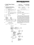
2.2.1 Installing SAS/SATA Drives in the Enclosure
Follow the steps below to install the 3.5-inch drives or 2.5-inch
drives into the drive tray.
a. Install the drives into the drive tray and make sure the holes of
the disk trays align with the holes of the drive.
Figure 2-1. Put 2.5-inch
SAS/SATA drive into disk
tray
Figure 2-2. Put 3.5-inch
SAS/SATA drive into disk
tray
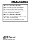
b. Turn the drive tray upside down and using a screwdriver to secure the drive to the drive tray by four of the mounting screws.
Figure 2-3. Drive carrier
with 2.5-inch SAS/SATA
drive
Figure 2-4. Drive carrier
with 3.5-inch SAS/SATA
drive
1. After installing the drive into the drive tray completely, make
sure the drive tray latch is open, then slide the drive tray with the
attached drive into the enclosure drive slot.
2. Gently slide the drive tray back of the enclosure drive slot until
the bottom of the open carrier handle makes contact with the
enclosure face plate.
30
HARDWARE INSTALLATION
3. Click the drive tray latch into position, then continuing to slide
the other drive tray into the slot.
Note:
To ensure proper airflow for enclosure cooling, each slot
should contain a drive tray.
4. Turn the key-lock to the proper position, using the “Star
Wrench L-Handle“ in the shopping box. The key-lock is unlock, if
the dot on its face is in the unlock orientation.
2.2.2 Installing SATA Drives with Interposer
Board
The interposer board is for usage with SATA drives. It provides
dual data path for redundant controller. If your enclosure has
two SAS RAID controllers and you are installing SATA drives, an
interposer board is required so that both expander modules can
31
HARDWARE INSTALLATION
access the SATA drives. Follow the steps below to install the SATA
drive with interposer board into the drive tray.
For 2.5-inch drive:
a. Prepare the interposer board.
b. Clip the interposer board into the drive tray.
c. Carefully slide the 2.5-inch drive toward the interposer board.
d. Turn the drive tray upside down and using a screwdriver to secure the drive to the drive tray by four of the mounting screws.
32
HARDWARE INSTALLATION
For 3.5-inch drive:
a. Slide the 3.5-inch drive toward the interposer board.
b. Position interposer board with drive toward the interposer
board slot with the latch point in the interposer board aligned with
the interposer board slot. Gently press down the module until it
snaps into place in the interposer board slot on the tray.
c. Turn the drive tray upside down and using a screwdriver to secure the drive to the drive tray by four of the mounting screws.
1. After installing the drive into the drive tray completely, make
sure the drive tray latch is open, then slide the drive tray with the
attached drive into the enclosure drive slot.
2. Gently slide the drive tray back of the enclosure drive slot until
the bottom of the open carrier handle makes contact with the
enclosure face plate.
33
HARDWARE INSTALLATION
3. Click the drive tray latch into position, then continuing to slide
the other drive tray into the slot.
4. Turn the key-lock to the proper position.
2.2.3 Removing Drives from the Enclosure
1. Don’t power the system off until the LED indicator on the drive
tray stop flashing.
2. Turn the key-lock to the unlock position.
3. Open the drive tray latch, then gently but firmly pull the drive
tray out from the slot.
2.3 Installing or Removing the SAS Series
RAID Controller in the Subsystem
A RAID subsystem with redundant function contains two controllers. A RAID subsystem with non-redundant function consists of
one controller. If two controllers are installed, a failover function is
offered. Control and monitoring of the enclosure elements can be
transferred from one controller to another in the event of a controller failure.
2.3.1 Installing the SAS RAID Controller in the
Subsystem
Follow the steps below to install the SAS RAID controller in the
subsystem:
1. Carefully slide the SAS RAID controller caddy into the empty
slot.
2. Push the SAS RAID controller caddy back of the slot until it is
firmly seated in the backplane connector.
3. Put the lever toward the subsystem and tighten the
thumbscrew which located on the left side of lever of the SAS
RAID controller caddy.
34
HARDWARE INSTALLATION
Note:
There are two slots for your SAS RAID controller. If you only
installed one in your subsystem, the other empty slot must
place a cover. To remove the cover, pull out on the thin tabs
on each end of the cover and slide the cover out of the slot.
2.3.2 Removing the SAS RAID Controller from the
Subsystem
Follow the steps below to remove the SAS RAID controller from
the subsystem:
1. Loosen the thumbscrew on left side of the lever, then gently
but firmly pull the SAS RAID controller caddy out from the slot.
2. After removed the SAS RAID controller caddy from the subsystem, place the cover in the empty slot.
35
HARDWARE INSTALLATION
Note:
At least one SAS RAID controller must be installed in the
RAID subsystem. If only one SAS RAID controller is installed,
it must be in the primary SAS RAID controller slot and the
other one must contain a cover.
2.3.3 Check Controller Memory Module
At least 1GB registered DDR2-800 cache memory is required in
each controller. Make sure the cache memory module is present
and seated firmly in the DIMM socket (DDR2-800) for series SAS
RAID subsystems.
2.3.3.1 Installing the DDR-2 SDRAM DIMM
1. Position the DIMM module toward the socket with the notches
in the module aligned with the receptive point on the socket.
2. Gently press down the module until it snaps into place in the
socket. The release tabs will hold the DIMM in place.
3. Make sure the selected registered DIMM module using x8 or
x16 device on the module.
Figure 2-1, Insert module vertically and press gently and firmly
down to ensure the module is peoperly seated into socket.
36
HARDWARE INSTALLATION
2.3.3.2 Removing the DDR-2 SDRAM DIMM
1. Use your thumbs to gently push the release tabs at both ends
of the socket to release it from the socket.
2.3.4 Adding a Battery Backup Module (Option)
Please refer to Appendix B for installing the BBM in your series
SAS RAID subsystem.
2.4 Installing and Removing the Power
Supply/Cooling Fan Modules
The subsystem supports two separate power modules. Each of
them contains an integrated power supply and one cooling fan.
2.4.1 Installing the Power Supply/Cooling Fan
Modules
1 Carefully slide the power supply/cooling fan modules into the
empty slot.
2 Push the module back of the slot until it is firmly seated in the
backplane connector.
3 Tighten the two thumbscrews to secure the power supply/cooling fan modules.
4. Connect the AC power cords to a grounded electrical outlet and
to the power supply.
37
HARDWARE INSTALLATION
Note:
The power supply/cooling fan modules are heavy. Be
carefully when you lift it up into the slot.
2.4.2 Removing a Power Supply/Cooling Fan
Modules
1. Turn off the power supply and unplug the AC power cords.
2. Loosen the thumbscrew on power supply/cooling fan module
then gently but firmly pull the power supply/cooling fan modules
out from the slot.
Note:
1. Power supply/cooling fan modules are hot-pluggable.
Provided one power supply/cooling fan module is functioning
normally, you can remove or replace the other while the
subsystem is powered on.
2. If you remove a fully functioning power supply/cooling fan
module, the fan speed in the remaining module will increase
significantly to provide adequate cooling. The fan speed will
decrease gradually when a new power supply/cooling fan
module is installed.
2.5 Installing the Power Cord Clamp
Using the included power cords, connect each power supply and
cooling fan unit to an AC power source. (manufacture recommends
that you use an uninterruptible power supply to protect your SAS
RAID subsystem.) The cable clamp prevents the power cord from
being accidently unplugged.
1. Connect the cable clamp to the cable strap. Opening the release
tab then insert the angled end of cable strap through the cable tie
frame. Facing up of cable strip smooth side and the other side facing down.
38
HARDWARE INSTALLATION
2. Connect the power cord and connect the cable strap with opening cable clamp to the power module. Using the release tab to
adjust the cable clamp to the suitable place.
3. Using cable clamp wrap the power cord and clip lock it. Repeat
step 1 to 3 to install the power cord clamp on the other side.
39
HARDWARE INSTALLATION
2.6 Connecting the RAID Subsystem
Once the SAS RAID subsystem has finished the installation of
hardware components, then you can connect it to a host computer.
The SAS RAID subsystem can be connected to a host computer
through the SAS, Fibre or iSCSI interface. User can select the right
cable connected to the host controller or other SAS JBOD enclosure.
2.6.1 Connecting to Host System
The external host connector is provided on the back of the SAS
RAID subsystem for connecting the array to server host adapter.
By installing host port adapter and RAID subsystem using the
correct external cables which is included in your SAS RAID
subsystem kits. Then connect SAS RAID subsystem and host port
adapter as shown below:
Figure 2-6 Connect SAS RAID subsystem and host adapter
2.6.2 Connecting Monitor Port
The SAS RAID subsystem is normally delivered with LCD preinstalled. Your SAS RAID subsystem can be configured by using
the LCD with keypad, a serial device (terminal emulation) or LAN
port.
40
HARDWARE INSTALLATION
• RS232C Port Connection
The SAS RAID subsystem can be configured via a VT-100
compatible terminal or a PC running a VT-100 terminal
emulation program. You can attach a serial (Character-Based)
terminal or server com port to the SAS RAID subsystem for
access to the text-based setup menu. There are two multiple
function on those RJ11. The J3 jumper is on the controller
board used to define the RS 232 port connectors (VT-100 for
expander/Debug and VT-100 for controller) function.
J3 jumper
RJ11 Beside Expander Port
RJ11 Beside LAN Port
1-2
Controller Debug Port
3-4 (Default)
Expander Port
Controller VT-100 Port
No Cap
Controller Debug Port
Controller VT-100 Port
Expander Port
Table 2-2, RS232C port function definition
• LAN Port Connection
The SAS RAID subsystem has embedded the TCP/IP & web
browser-based RAID manager in the firmware(method 3).
User can remote manage the SAS RAID subsystem without
adding any user specific software (platform independent) via
standard web browsers directly connected to the 10/100/1000
Ethernet RJ45 LAN port. Connect Ethernet port of the SAS RAID
subsystem using the included Ethernet cable and then to a LAN
port or LAN switch.
41
HARDWARE INSTALLATION
2.6.3 Power Up the RAID Subsystem
There is one main power on/off switch located on the rear side of
the RAID subsystem. This on/off power switch is used to apply or
remove power from the power supply to the RAID subsystem.
Turning off subsystem power with this switch removes the main
power but keeps standby power supplied to the RAID subsystem.
Therefore, you must unplug the power cord before subsystem
servicing.
The cooling fan included on the power supply run on separate
control circuits from the power supply. Therefore, if one power
supply fails, the failed power’s fan continues to work on the power
supplied from the other good power supply.
The installation is completed. You can use your SAS RAID subsystem.
Note:
A power supply/cooling fan module can be removed from a
powered-on subsystem; however, the subsystem should shut
down if overheating occurs.
2.7 Configuring RAID Subsystems
There are often multiple ways to accomplish the same configuration
and maintenance tasks for your SAS RAID subsystem. The SAS
RAID subsystem is normally delivered with LCD preinstalled. Your
SAS RAID subsystem can be configured by using the LCD with
keypad, a serial device (terminal emulation) or LAN port. Turn to
the relative section of RAID configuration in the user manual for
information about detail configuring RAID arrays.
42
HARDWARE INSTALLATION
2.7.1 Configuring Method
• Method 1: LCD Panel with Keypad
You can use LCD front panel and keypad function to simply create
the RAID volume. The LCD status panel also informs you of the
disk array’s current operating status at a glance. For additional
information on using the LCD to configure the RAID subsystem
see the Chapter 4 of LCD Configuration.
The LCD provides a system of screens with areas for information,
status indication, or menus. The LCD screen displays up to two
lines at a time of menu items or other information.
The initial screen is shown as below:
• Method 2: RS-232 Port Connection
For additional information on using the RS-232 port to configure
the SAS RAID subsystem see the Chapter 5 of VT-100 Utility
Configuration.
• Method 3: LAN Port Connection
For additional information on using the LAN port to configure
the RAID subsystem see the Chapter 6 of Web Browser-Based
Configuration.
Note:
It's a good ideal to turn on your SAS RAID subsystem
before turning on the host computer. This will insure that
the host computer recognize the volumes and drivers in
the SAS RAID subsystem.
43
HARDWARE INSTALLATION
2.7.2 Format, Partition and Mount the SAS RAID
Subsystem Volumes
Safety checks the installation. Connect all power cords. Turn on
the AC power switch at the rear of host computer then press the
power button at the front of the host computer.
After you create a unit, it needs to be partitioned, formatted,
and mounted by the operating system. There are various steps,
that depend on what operating system you are using (Windows,
Linux, FreeBSD or Mac, etc.). Detailed steps for each operating
system are provided on their disk utility. After that, the SAS RAID
subsystem can be fully used.
44
CONFIGURATION METHOD
3. Configuration Methods
After the hardware installation, the SAS/SATA disk drives connected to
the SAS RAID subsystem must be configured and the volume set units
initialized before they are ready to use. This can be accomplished by
one of the following methods:
• Front panel touch-control keypad.
• VT100 terminal connected through the controller’s serial port.
• Firmware-embedded & web browser-based RAID manager/SNMP
agent/SMTP via the controller’s 10/100/1000 LAN port.
Those user interfaces can access the built-in configuration and administration utility that resides on the controller’s firmware. They provide
complete control and management of the controller and disk arrays,
eliminating the need for additional hardware or software.
Note:
The SAS RAID subsystem allows only one method to access
menus at a time.
3.1 Using Local Front Panel Touch-control
Keypad
The front panel keypad and liquid crystal display (LCD) is the primary user interface for the SAS RAID subsystem. All configuration
and management of the controller and its properly connected disk
arrays can be performed from this interface.
The front panel keypad and LCD are connected to the RAID subsystem to access the built-in configuration and administration utility that resides in the controller’s firmware. Complete control and
management of the array’s physical drives and logical units can be
performed from the front panel, requiring no additional hardware
or software drivers for that purpose.
45
CONFIGURATION METHOD
A touch-control keypad and a liquid crystal display (LCD) mounted
on the front of the RAID subsystem is the primary operational interface and monitor display for the disk array controller. This user
interface controls all configuration and management functions for
the RAID subsystem it is properly connected.
The LCD provides a system of screens with areas for information,
status indication, or menus. The LCD screen displays up to two
lines at a time of menu items or other information.
The initial screen is shown as the following:
Function Key Definitions:
The four function keys at the button of the front perform the following functions:
Key
Function
Up Arrow
Use to scroll the cursor Upward/Rightward
Down Arrow
Use to scroll the cursor Downward/Leftward
ENT Key
Submit select ion function (Confirm a selected item)
ESC Key
Return to previous screen (Exit a selection configuration)
There are a variety of failure conditions that cause the SAS RAID
subsystem monitoring LED to light. Following table provides a summary of the front panel LED.
Panel LED
46
Normal Status
Problem Indication
Power LED
Solid green, when power on
Unlit, when power on
Busy LED
Blinking amber during host accesses SAS RAID subsystem
Unlit or never flicker
Fault LED
Unlit
Solid red
CONFIGURATION METHOD
For additional information on using the LCD panel and keypad to
configure the SAS RAID subsystem see ‘‘LCD Configuration Menu”
on Chapter 4.
3.2 VT100 Terminal (Using the controller’s
serial port)
The serial port on the SAS RAID subsystem’s front can be used
in VT100 mode. The provided interface cable converts the RS232
signal of the 6-pin RJ11 connector on the RAID subsystem into a
9-pin D-Sub female connector. The firmware-based terminal array
management interface can access the array through this RS-232
port. You can attach a VT-100 compatible terminal or a PC running
a VT-100 terminal emulation program to the serial port for accessing the text-based setup menu.
3.2.1 RAID Subsystem RS-232C Port Pin Assignment
To ensure proper communications between the RAID subsystem
and the VT-100 Terminal Emulation, Please configure the VT100
terminal emulation settings to the values shown below:
Terminal requirment
Connection
Null-modem cable
Baud Rate
115,200
Data bits
8
Stop
1
Flow Control
None
The VT-100 port for the SAS RAID configuration, please refer to
table 2-2 in chapter 2. The controller VT-100 RJ11 connector pin
assignments are defined as below.
Pin Assignment
Pin
Definition
Pin
Definition
1
RTS (RS232)
4
GND
2
RXD (RS232)
5
GND
3
TXD (RS232)
6
GND
47
CONFIGURATION METHOD
Keyboard Navigation
The following definition is the VT-100 RAID configuration utility
keyboard navigation.
Key
Function
Arrow Key
Move cursor
Enter Key
Submit selection function
ESC Key
Return to previous screen
L Key
Line draw
X Key
Redraw
3.2.2 Start-up VT100 Screen
By connecting a VT100 compatible terminal, or a PC operating in
an equivalent terminal emulation mode, all SAS RAID subsystem
monitoring, configuration and administration functions can be
exercised from the VT100 terminal.
There are a wide variety of Terminal Emulation packages, but for
the most part they should be very similar. The following setup
procedure is an example setup VT100 Terminal in Windows system using Hyper Terminal use Version 3.0 or higher.
Step 1. From the Desktop open the start menu. Pick Programs,
Accessories, Communications and Hyper Terminal. Open Hyper
Terminal (requires version 3.0 or higher)
Step 2. Open HYPERTRM.EXE and enter a name for your Terminal. Click OK.
48
CONFIGURATION METHOD
Step 3. Select an appropriate connecting port in your Terminal.
Click OK. Configure the port parameter settings. Bits per second:
“115200”, Data bits: “8”, Parity: ”None”, Stop bits: “1”, Flow
control:” None”. Click “OK”
Step 4. Open the File menu, and then open Properties.
Step 5. Open the Settings Tab.
49
CONFIGURATION METHOD
Step 6. Open the Settings Tab. Function, arrow and ctrl keys act
as: Terminal Keys, Backspace key sends: “Crtl+H”, Emulation:
VT100, Telnet terminal: VT100, Back scroll buffer lines: 500. Click
OK.
Now, the VT100 is ready to use.
After you have finished the VT100 Terminal setup, you may press
“ X “ key (in your Terminal) to link the RAID subsystem and Terminal together.
Press” X ” key to display the disk array Monitor Utility screen on
your VT100 Terminal.
50
CONFIGURATION METHOD
3.3 Web Browser-based RAID Manager
To configure SAS RAID subsystem on a local or remote machine,
you need to know its IP Address. The IP address will default show
in the "LCD" screen or "Ethernet Configuration" option on the
VT100 utility configration. Launch your firmware-embedded TCP/
IP & web browser-based RAID manager by entering http://[IP
Address] in the web browser.
The provided LAN interface cable connects the SAS RAID
subsystem LAN port into a LAN port from your local network.
Use only shield cable to avoid radiated emission that may cause
interruptions. To ensure proper communications between the
RAID subsystem and web browser-based RAID management,
Please connect the SAS RAID subsystem LAN port to any LAN
switch port.
The SAS RAID subsystem has embedded the TCP/IP & web
browser-based RAID manager in the firmware. User can remote
manage the SAS RAID subsystem without adding any user specific
software (platform independent) via standard web browsers
directly connected to the 10/100/1000 RJ45 LAN port.
The storage console current configuration screen displays the
current configuration of your SAS RAID subsystem. Detail
procedures please refer to the Chapter 6 Web Browser-based
Configuration method.
Note:
You must be logged in as administrator with local admin rights
on the remote machine to remotely configure it.
The SAS RAID subsystem default user name is “admin” and the
password is “0000”.
3.4 Configuration Menu Tree
The following is an expansion of the menus in configuration utility that can be accessed through the LCD panel, RS-232 serial port
and LAN port.
51
CONFIGURATION METHOD
Note:
Ethernet Configuration, Alert By Mail Config, and SNMP Config
can only be set in the web-based configuration.
52
LCD CONFIGURATION MENU
4. LCD Configuration Menu
After the hardware installation, the disk drives connected to the RAID
subsystem must be configured and the volume set units initialized
before they are ready to use. This can be also accomplished by the
front panel touch-control keypad.
The LCD module on the front side can access the built-in configuration
and administration utility that resides in the controller’s firmware.
To complete control and management of the array’s physical drives
and logical units can be performed from the front panel, requiring no
additional hardware or software drivers for that purpose.
The LCD provides a system of screens with areas for information,
status indication, or menus. The LCD screen displays up to two lines at
a time of menu items or other information.
The LCD display front panel function keys are the primary user
interface for the RAID subsystem. Except for the "Firmware update",
all configurations can be performed through this interface.
Function Key Definitions
The four function keys at the front panel of the button perform the
following functions:
Key
Function
Up Arrow
Use to scroll the cursor Upward/Rightward
Down Arrow
Use to scroll the cursor Downward/Leftward
ENT Key
Submit select ion function (Confirm a selected item)
ESC Key
Return to previous screen (Exit a selection configuration)
4.1 Starting LCD Configuration Utility
After power on the SAS RAID subsystem, press ENT to verify
password for entering the main menu from LCD panel. Using the
UP/DOWN buttons to select the menu item, then press ENT to
confirm it. Press ESC to return to the previous screen.
53
LCD CONFIGURATION MENU
4.2 LCD Configuration Utility Main Menu
Options
Select an option, related information or submenu items to display
beneath it. The submenus for each item are explained on the section 4.7.2. The configuration utility main menu options are:
Option
Description
Quick Volume And Raid Set
Setup
Create a default configurations which are based
on the number of physical disk installed
Raid Set Functions
Create a customized RAID set
Volume Set Functions
Create a customized volume set
Physical Drive Functions
View individual disk information
Raid System Functions
Setting the raid system configurations
Ethernet Configuration
LAN port setting
Show System Events
Record all system events in the buffer
Clear All Event Buffers
Clear all event buffer information
Hardware Monitor Information
Show all system environment status
Show System information
View the controller information
4.3 Configuring Raid Sets and Volume Sets
You can use “Quick Volume And Raid Set Setup" or "Raid Set
Functions" and "Volume Set Functions" to configure RAID sets and
volume sets from LCD panel. Each configuration method requires
a different level of user input. The general flow of operations for
RAID set and volume set configuration is:
Step
54
Action
1
Designate hot spares/pass-through (optional)
2
Choose a configuration method
3
Create RAID set using the available physical drives
4
Define volume set using the space in the RAID set
5
Initialize the volume set and use volume set in the host OS
LCD CONFIGURATION MENU
4.4 Designating Drives as Hot Spares
To designate drives as hot spares, press ENT to enter the main
menu. Press UP/DOWN buttons to select the “Raid Set Functions”
option and then press ENT. All RAID set functions will be displayed.
Press UP/DOWN buttons to select the “Create Hot Spare Disk”
option and then press ENT. The first unused physical device connected to the current RAID subsystem appears. Press UP/DOWN
buttons to scroll the unused physical devices and select the target
disk to assign as a hot spare and press ENT to designate it as a
hot spare.
4.5 Using Easy RAID Configuration
In “Quick Volume And Raid Setup” configuration, the RAID set you
create is associated with exactly one volume set, and you can modify the Raid Level, Stripe Size, and Capacity. Designating drives as
hot spares will also combine with RAID level in this setup.
The volume set default settings will be:
Parameter
Setting
Volume Name
Volume Set # 00
SAS Port#/LUN Base/LUN
0/0/0
Cache Mode
Write-Back
Tag Queuing
Yes
The default setting values can be changed after configuration is
completed.
Follow the steps below to create RAID set using “Quick Volume And
Raid Setup” configuration:
Step
1
Action
Choose “Quick Volume And Raid Setup” from the main menu. The available RAID levels with hot spare for the current volume set drive are
displayed.
55
LCD CONFIGURATION MENU
56
2
It is recommended to use drives have same capacity in a specific array. If
you use drives with different capacities in an array, all drives in the RAID
set will select the lowest capacity of the drive in the RAID set.
The numbers of physical drives in a specific array determine the RAID
levels that can be implemented with the array.
RAID 0 requires 1 or more physical drives
RAID 1 requires at least 2 physical drives
RAID 1+Spare requires at least 3 physical drives
RAID 3 requires at least 3 physical drives
RAID 5 requires at least 3 physical drives
RAID 3 +Spare requires at least 4 physical drives
RAID 5 + Spare requires at least 4 physical drives
RAID 6 + Spare requires at least 5 physical drives.
Using UP/DOWN buttons to select RAID level for the volume set and
press ENT to confirm it.
3
Using UP/DOWN buttons to create the current volume set capacity size
and press ENT to confirm it. The available stripe sizes for the current
volume set are displayed.
4
Using UP/DOWN buttons to select the current volume set stripe size
and press ENT key to confirm it. This parameter specifies the size of the
stripes written to each disk in a RAID 0, 1, 10(1E), 5 or 6 volume set.
You can set the stripe size to 4 KB, 8 KB, 16 KB, 32 KB, 64 KB, or 128
KB. A larger stripe size provides better-read performance, especially if
your computer does mostly sequential reads. However, if you are sure
that your computer does random read requests more often, choose a
small stripe size.
5
When you finished defining the volume set, press ENT to confirm the
“Quick Volume And Raid Set Setup” function.
6
Press ENT to define “FGrnd Init (Foreground initialization)” or press ESC
to define “BGrnd Init (Background initialization)“. When “FGrnd Init", the
initialization proceeds must be completed before the volume set ready
for system accesses. When “BGrnd Init", the initialization proceeds as a
background task, the volume set is fully accessible for system reads and
writes. The operating system can instantly access to the newly created
arrays without requiring a reboot and waiting the initialization complete.
7
Initialize the volume set you have just configured.
8
If you need to add additional volume set, using main menu “Create Volume Set” functions.
LCD CONFIGURATION MENU
4.6 Using Raid Set and Volume Set
Functions
In “Raid Set Function”, you can use the create RAID set function to
generate the new RAID set. In “Volume Set Function”, you can use
the create volume set function to generate its associated volume
set and parameters. If the current SAS RAID subsystem has unused
physical devices connected, you can choose the “Create Hot Spare”
option in the “Raid Set Function” to define a global hot spare.
Select this method to configure new RAID sets and volume sets.
This configuration option allows you to associate volume set with
partial and full RAID set.
Step
Action
1
To setup the hot spare (option), choose “Raid Set Function” from the main
menu. Select the “Create Hot Spare” and press ENT to set the hot spare.
2
Choose “Raid Set Function” from the main menu. Select the “Create Raid
Set” and press ENT.
3
Select a drive for RAID set from the SAS/SASA/SSD drive connected to
the SAS RAID subsystem.
4
Press UP/DOWN buttons to select specific physical drives. Press the ENT
key to associate the selected physical drive with the current RAID set.
Recommend use drives has same capacity in a specific RAID set. If you
use drives with different capacities in an array, all drives in the RAID set
will select the lowest capacity of the drive in the RAID set.
The numbers of physical drives in a specific RAID set determine the RAID
levels that can be implemented with the RAID set.
RAID 0 requires 1 or more physical drives per RAID set.
RAID 1 requires at least 2 physical drives per RAID set.
RAID 1 + Spare requires at least 3 physical drives per RAID set.
RAID 3 requires at least 3 physical drives per RAID set.
RAID 5 requires at least 3 physical drives per RAID set.
RAID 3 + Spare requires at least 4 physical drives per RAID set.
RAID 5 + Spare requires at least 4 physical drives per RAID set.
RAID 6 + Spare requires at least 5 physical drives per RAID set.
5
After adding physical drives to the current RAID set as desired, press ENT
to confirm the “Create Raid Set” function.
6
An edit the RAID set name screen appears. Enter 1 to 15 alphanumeric
characters to define a unique identifier for a RAID set. The default RAID
set name will always appear as Raid Set. #. Press ENT to finish the name
editing.
57
LCD CONFIGURATION MENU
7
Press ENT when you are finished creating the current RAID set. To
continue defining another RAID set, repeat step 3. To begin volume set
configuration, go to step 8.
8
Choose “Volume Set Functions” from the main menu. Select the “Create
Volume Set” and press ENT .
9
Choose one RAID set from the screen. Press ENT to confirm it.
10
The volume set attributes screen appears:
The volume set attributes screen shows the volume set default configuration value that is currently being configured. The volume set attributes
are:
Volume Name,
Raid Level,
Stripe Size,
Cache Mode,
SAS Port/SAS LUN Base/SAS LUN, Fibre Port/ Fibre LUN Base/Fibre LUN
and iSCSI Target Node/iSCSI LUN and
Tagged Queuing.
All values can be changed by the user. Press the UP/DOWN buttons to
select the attributes. Press the ENT to modify each attribute of the default value. Using UP/DOWN buttons to select attribute value and press
the ENT to accept the default value.
11
After user completed modifying the attribute, press ESC to enter the select capacity for the volume set. Using the UP/DOWN buttons to set the
volume set capacity and press ENT to confirm it.
12
When you finished defining the volume set, press ENT to confirm the
creation function.
13
Press ENT to define “FGrnd Init (Foreground initialization)” or press ESC
to define “BGrnd Init (Background initialization)“. The controller will begin to initialize the volume set, you have just configured. If space remains
in the RAID set, the next volume set can be configured. Repeat steps 8 to
13 to configure another volume set.
4.7 Navigation Map of the LCD
The password option allows user to set or clear the RAID subsystem’s password protection feature. Once the password has been
set, the user can only monitor and configure the RAID subsystem
by providing the correct password. The password is used to protect
the RAID subsystem from unauthorized entry. The RAID subsystem will check the password only when entering the main menu
from the initial screen. The RAID subsystem will automatically go
back to the initial screen when it does not receive any command in
five minutes. The RAID subsystem's password is default setting at
“0000” by the manufacture.
58
LCD CONFIGURATION MENU
4.7.1 Quick Volume And Raid Setup
“Quick Volume And Raid Setup” is the fastest way to prepare a
RAID set and volume set. It only needs a few keystrokes to complete it. Although disk drives of different capacity may be used in
the RAID set, it will use the smallest capacity of the disk drive as
the capacity of all disk drives in the RAID set. The “Quick Volume
And Raid Setup” option creates a RAID set with the following
properties:
Figure 4.7.1-1
1. All of the physical disk drives are contained in a RAID set.
2. The RAID levels associated with hot spare, capacity, and
stripe size are selected during the configuration process.
3. A single volume set is created and consumed all or a portion
of the disk capacity available in this RAID set.
4. If you need to add additional volume set, using main menu
“Volume Set Functions”. Detailed procedure refer to this
chapter section 4.7.3.
4.7.2 Raid Set Functions
User manual configuration can complete control of the RAID set
setting, but it will take longer time to complete than the “Quick
Volume And Raid Setup” configuration. Select the “Raid Set Functions” to manually configure the RAID set for the first time or
deletes existing RAID set and reconfigures the RAID set.
To enter a “Raid Set Functions”, press ENT to enter the main
menu. Press UP/DOWN buttons to select the “Raid Set Functions” option and then press ENT to enter further submenus. All
RAID set submenus will be displayed.
59
LCD CONFIGURATION MENU
Figure 4.7.2-1
4.7.2.1 Create A New Raid Set
For detailed procedure please refer to chapter section 4.6.
4.7.2.2 Delete Raid Set
Press UP/DOWN buttons to choose the “Delete Raid Set” option. Using UP/DOWN buttons to select the RAID set number
that user wants to delete and then press ENT to accept the
RAID set number. The confirmation screen appears, then press
ENT to accept the delete RAID set function. The double confirmation screen appears, then press ENT to make sure of the
delete existed RAID set function
60
LCD CONFIGURATION MENU
4.7.2.3 Expand Raid Set
Instead of deleting a RAID set and recreating it with additional
disk drives, the “Expand Existed Raid Set” function allows the
user to add disk drives to the RAID set that was created.
To expand existed RAID set, press UP/DOWN buttons to
choose the “Expand Raid Set” option. Using UP/DOWN buttons
to select the RAID set number that user wants to expand and
then press ENT to accept the RAID set number. If there is an
available disk, then the “Select Drive” appears. Using UP/
DOWN buttons to select the target disk and then press ENT
to select it. Press ENT to start expanding the existed RAID set.
The new added capacity can defined one or more volume sets.
Follow the instruction presented in the “Volume Set Function” to
create the volume sets.
Migrating occurs when a disk is added to a RAID set. Migration
status is displayed in the RAID status area of the “Raid Set information” when a disk is added to a RAID set. Migrating status
is also displayed in the associated volume status area of the
volume set information when a disk is added to a RAID set.
Note:
1. Once the “Expand Raid Set” process has started, user
can not stop it. The process must be completed.
2. If a disk drive fails during RAID set expansion and a hot
spare is available, an auto rebuild operation will occur after
the RAID set expansion completes.
4.7.2.4 Offline Raid Set
Press UP/DOWN buttons to choose the “Offline Raid Set”
option. This function is for customer being able to unmount and
remount a multi-disk volume. All hdds of the selected RAID set
will be put into offline state, spun down and fault LED will be in
fast blinking mode.
61
LCD CONFIGURATION MENU
4.7.2.5 Activate Incomplete RaidSet
When one of the disk drive is removed or loosed connection
in power off state, the RAID set state will change to “Incomplete State”. If user wants to continue to work, when the RAID
subsystem is power on. User can use the “Activate Incomplete
RaidSet” option to active the RAID set. After user completed the
function, the “Raid State” will change to “Degraded Mode”.
4.7.2.6 Create Hot Spare Disk
Please refer to this chapter section 4.4. Designating drives as
hot spares.
4.7.2.7 Delete Hot Spare Disk
To delete hot spare, press UP/DOWN buttons to choose the
“Delete Hot Spare Disk” option. Using UP/DOWN buttons to
select the hot spare number that user wants to delete and then
press ENT to select it. The confirmation screen appears and
press ENT to delete the hot spare.
4.7.2.8 Display Raid Set Information
Choose the “Display Raid Set Information” option and press
ENT. Using UP/DOWN buttons to select the RAID set number.
Then the RAID set information will be displayed.
Using UP/DOWN buttons to see the RAID set information, it
will show Raid Set Name, Total Capacity, Free Capacity, Number
of Member Disks, Min. Member Disk Capacity, Raid Set State
and Raid Power Status.
62
LCD CONFIGURATION MENU
4.7.3 Volume Set Functions
A volume set is seen by the host system as a single logical device. It is organized in a RAID level with one or more physical
disks. RAID level refers to the level of data performance and protection of a volume set. A volume set capacity can consume all
or a portion of the disk capacity available in a RAID set. Multiple
volume sets can exist on a group of disks in a RAID set. Additional volume sets created in a specified RAID set will reside on
all the physical disks in the RAID set. Thus each volume set on
the RAID set will have its data spread evenly across all the disks
in the RAID set.
To enter the “Volume Set Functions”, press ENT to enter the main
menu. Press UP/DOWN buttons to select the “Volume Set Functions” option and then press ENT to enter further submenus. All
volume set submenus will be displayed.
Figure 4.7.3.1-1
63
LCD CONFIGURATION MENU
4.7.3.1 Create Raid Volume Set
To create a volume set, please refer to this chapter section 4.7,
using “Raid Set Functions”and “Volume Set Functions”. The volume set attributes screen shows the volume set default configuration values that have currently being configured.
The attributes for RAID subsystem series are Volume Name,
Raid Level, Stripe Size, Cache Mode, SAS Port/ SAS LUN Base/
SAS LUN, Fibre Port/Fibre LUN Base/Fibre LUN, iSCSI Target
Node/ iSCSI LUN and Tagged Queuing. See Figure 4.7.3.1-1
All values can be changed by user. Press the UP/DOWN buttons
to select attributes. Press ENT to modify the default value. Using the UP/DOWN buttons to select attribute value and press
ENT to accept the default value. The following is the attributes
descriptions. Please refer to this chapter section 4.7 using “Raid
Set Functions” and “Volume Set Functions” to complete the create volume set function.
4.7.3.1.1 Volume Name
The default volume name will always appear as volume set
#. You can rename the volume set name providing it does not
exceed the 15 characters limit.
4.7.3.1.2 Raid Level
The RAID subsystem can only set the RAID level 0, 1, 10(1E), 3,
5 and 6 on the LCD configuration.
4.7.3.1.3 Stripe Size
This parameter sets the size of the segment written to each
disk in a RAID 0, 1, 10(1E), 5 or 6 logical drive. You can set the
stripe size to 4 KB, 8 KB, 16 KB, 32 KB, 64 KB, or 128 KB.
A larger stripe size produces better-read performance,
especially if your computer does mostly sequential reads.
However, if you are sure that your computer does random reads
more often, select a small stripe size.
64
LCD CONFIGURATION MENU
4.7.3.1.4 Cache Mode
User can set the cache mode as “Write-Through” or “Write-Back
”.
4.7.3.1.5 SAS Port/SAS LUN Base/SAS LUN
SAS Port: Two 4-PHY links SAS ports can be applied to the RAID
subsystem. The RAID subsystem supports Port 0,1 and 0&1
Cluster option.
SAS LUN base: Each SAS device attached to the SAS host
adapter must be assigned a unique SAS ID number. A SAS port
can connect up to 128(16*8) volume sets. The RAID subsystem
is as a large SAS device. We should assign an LUN base from a
list of SAS LUN Base.
SAS LUN: Each LUN Base can support up to 8 SAS LUNs. Most
SAS port host adapter treats each SAS LUN like a SAS disk.
• Fibre Port/Fibre LUN Base/Fibre LUN
Fibre Port: Four 8Gbps Fibre channel can be applied to the SAS
RAID subsystem. Choose the Fibre Host: “0”, “1” or “0&1 Cluster” option. A “Select Fibre Channel” appears, select the channel number and press ENT key to confirm it.
Fibre LUN Base: Each fibre device attached to the Fibre card,
as well as the card itself, must be assigned a unique fibre ID
number. A Fibre channel can connect up to 128(16*8) volume
sets. The RAID subsystem is as a large Fibre device. We should
assign an LUN base from a list of Fibre LUN Base.
Fibre LUN: Each Fibre LUN base can support up to 8 LUNs. Most
Fibre channel host adapter treats each LUN like a Fibre disk.
• iSCSI Target Node/iSCSI LUN
iSCSI Target Node: A iSCSI RAID subsystem can connect up to
16 target nodes. The iSCSI RAID subsystem is as a large SAS/
SATA device. We should assign a Node from a list of Target
Node. A iSCSI channel can connect up to 128(16*8) volume
sets.
65
LCD CONFIGURATION MENU
iSCSI LUN: Each Target Node can support up to 8 LUNs. Most
iSCSI host adapter treats each LUN like a SAS/SATA disk.
4.7.3.1.6 Tagged Queuing
The "Enabled" option is useful for enhancing overall system
performance under multi-tasking operating systems. The
Tagged Command Queuing (TCQ) function controls the SAS
command tag queuing support for each drive channel. This
function should normally remain enabled. Disable this function
only when using older SAS drives that do not support command
tag queuing.
4.7.3.1.7 Initialization Mode
Press ENT to define “FGrnd Init (Foreground initialization)” or
press ESC to define “BGrnd Init (Background initialization)“.
When “FGrnd Init", the initialization proceeds must be
completed before the volume set ready for system accesses.
When “BGrnd Init", the initialization proceeds as a background
task, the volume set is fully accessible for system reads and
writes. The operating system can instantly access to the newly
created arrays without requiring a reboot and waiting the initialization complete.
4.7.3.2 Delete Existed Volume Set
Choose the "Delete Existed Volume Set" option. Using UP/
DOWN buttons to select the RAID set number that user wants
to delete and press ENT. The confirmation screen appears, and
then press ENT to accept the delete volume set function. The
double confirmation screen appears, then press ENT to make
sure of the delete existed volume set.
4.7.3.3 Modify Volume Set Attribute
Use this option to modify volume set configuration. To modify
volume set attributes from RAID set system function, press UP/
DOWN buttons to choose the “Modify Volume Set Attribute” option. Using UP/DOWN buttons to select the RAID set number
that user wants to modify and press ENT.
66
LCD CONFIGURATION MENU
Press ENT to select the existed volume set attribute. The volume set attributes screen shows the volume set setting configuration attributes that were currently being configured. The
attributes are Raid Level, Stripe Size, Cache Mode, SAS Port/
SAS LUN Base/SAS LUN, Fibre Port/Fibre LUN Base/Fibre LUN,
iSCSI Target Node/ iSCSI LUN and Tagged Queuing and Volume
Name (number). All values can be modified by user. Press the
UP/DOWN buttons to select attribute. Press ENT to modify the
default value. Using the UP/DOWN buttons to select attribute
value and press the ENT to accept the selection value. Choose
this option to display the properties of the selected volume set.
Figure 4.7.3.2-1
4.7.3.3.1 Volume Set Migration
Migrating occurs when a volume set is migrating from one RAID
level to another, a volume set strip size changes, or when a disk
is added to a RAID set. Migration status is displayed in the volume state area of the “Display Volume Set” Information.
67
LCD CONFIGURATION MENU
4.7.3.4 Check Volume Set Consistency
Use this option to check volume set consistency. To check volume set consistency from volume set system function, press
UP/DOWN buttons to choose the “Check Volume Set Consistency” option. Using UP/DOWN button to select the RAID set
number that user wants to check and press ENT. The confirmation screen appears, press ENT to start the check volume set
consistency.
4.7.3.5 Stop Volume Set Consistency Check
Use this option to stop volume set consistency check. To stop
volume set consistency check from volume set system function,
press UP/DOWN buttons to choose the "Stop Volume Set
Consistency Check" option and then press ENT to stop the check
volume set consistency.
4.7.3.6 Display Volume Set Information
To display volume set information from volume set function,
press UP/DOWN buttons to choose the "Display Volume Set
Information" option. Using UP/DOWN buttons to select the
RAID set number that user wants to show and press ENT. The
volume set information will show Volume Set Name, Raid Set
Name, Volume Capacity, Port Attribute, RAID Level, Stripe Size,
Member Disks, Cache Attribute and Tagged Queuing. All values
can not be modified by this option.
4.7.4 Physical Drive Functions
Choose this option from the main menu to select a physical disk
and to perform the operations listed below. To enter a physical
drive functions, press ENT to enter the main menu. Press UP/
DOWN buttons to select the "Physical Drive Functions" option
and then press ENT to enter further submenus. All physical drive
submenus will be displayed.
68
LCD CONFIGURATION MENU
Figure 4.7.4-1
Figure 4.7.4-2
69
LCD CONFIGURATION MENU
4.7.4.1 Display Drive Information
Using UP/DOWN buttons to choose the “Display Drive Information” option and press ENT. Using UP/DOWN buttons to select
the drive SAS/SATA number that user want to display. The drive
information will be displayed. The SATA drive information screen
shows the Model Name, Serial Number, Firmware Rev., Device
Capacity, Current SATA, Supported SATA, and Device State.
4.7.4.2 Create Pass-Through Disk
Disk is not controlled by the RAID subsystem’s firmware and
thus can not be a part of a RAID set. The disk is available to the
operating system as an individual disk. It is typically used on a
system where the operating system is on a disk not controlled
by the RAID subsystem’s firmware. Using UP/DOWN buttons to
choose the “Create Pass-Through Disk” option and press ENT.
Using UP/DOWN buttons to select the drive SAS/SATA number
that user want to create. The drive attributes will be displayed.
The attributes for pass-through disk show the Volume Cache
Mode, SAS Port/ SAS LUN Base/SAS LUN, Fibre Port/Fibre LUN
Base/Fibre LUN, iSCSI Target Node/iSCSI LUN and Tagged
Queuing .
All values can be changed by user. Press the UP/DOWN buttons
to attribute and then press ENT to modify the default value. Using the UP/DOWN buttons to select attribute value and press
ENT to accept the selection value.
4.7.4.3 Modify Pass-Through Disk
To modify pass-through disk attributes from pass-through drive
pool, press UP/DOWN buttons to choose the “Modify PassThrough Disk” option, and then press ENT. The select drive
function menu will show all pass-through disk number items.
Using UP/DOWN buttons to select the pass-through disk that
user wants to modify and press ENT. The attributes screen
shows the pass through disk setting values that were currently
being configured.
The attributes for pass-through disk are the Volume Cache
70
LCD CONFIGURATION MENU
Mode, Tagged Command Queuing and SAS Port/ SAS LUN Base/
SAS LUN, Fibre Port/Fibre LUN Base/Fibre LUN, iSCSI Target
Node/ iSCSI LUN. All values can be modified by user. Using UP/
DOWN buttons to select attribute. Press ENT to modify the
default value. Using the UP/DOWN buttons to select attribute
value and press ENT to accept the selection value. After completing the modification, press ESC to enter the confirmation
screen and then press ENT to accept the “Modify Pass-Through
Disk” function.
4.7.4.4 Delete Pass-Through Disk
To delete pass through disk from the pass-through drive pool,
press UP/DOWN buttons to choose the “Delete Pass-Through
Disk” option, and then press ENT. The “Select Drive Function”
menu will show all pass-through disk number items. Using UP/
DOWN buttons to select the pass-through disk that user wants
to delete and press ENT. The delete pass-through confirmation
screen will appear, press ENT to delete it.
4.7.4.5 Identify The Selected Drive
To prevent removing the wrong drive, the selected disk fault LED
indicator will light for physically locating the selected disk when
the “Identify The Selected Drive” function is selected.
To identify selected drive from the physical drive pool, press
UP/DOWN buttons to choose the “Identify The Selected Drive”
option, then press ENT key. The “Select Drive function “menu
will show all physical drive number items. Using UP/DOWN
buttons to select the disk that user want to identify and press
ENT. The selected disk fault LED indicator will flash.
4.7.5 Raid System Functions
To enter a "Raid System Functions", press ENT to enter the main
menu. Press UP/DOWN buttons to select the "Raid System
Functions" option and then press ENT to enter further submenus.
All RAID system submenus will be displayed. Using UP/DOWN
buttons to select the submenus option and then press ENT to
enter the selection function.
71
LCD CONFIGURATION MENU
Figure 4.7.5-1
72
LCD CONFIGURATION MENU
4.7.5.1 Mute The Alert Beeper
The “Mute The Alert Beeper” function item is used to control the
RAID subsystem beeper. Select No and press ENT button to
turn the beeper off temporarily. The beeper will still activate on
the next event.
4.7.5.2 Alert Beeper Setting
The “Alert Beeper Setting” function item is used to disable or
enable the RAID subsystem’s alarm tone generator. Using the
UP/DOWN buttons to select “Alert beeper Setting” and press
ENT to accept the selection. After completed the selection, the
confirmation screen will be displayed and then press ENT to
accept the function. Select the “Disabled” and press ENT key in
the dialog box to turn the beeper off.
4.7.5.3 Change Password
To set or change the RAID subsystem’s password, press the UP/
DOWN buttons to select “Change Password” option and then
press ENT to accept the selection. The “New Password:” screen
appears and enter new password that users want to change.
Using UP/DOWN buttons to set the password value. After
completed the modification, the confirmation screen will be displayed and then press ENT to accept the function. To disable the
password, press ENT only in the “New Password:” column. The
existing password will be cleared. No password checking will occur when entering the main menu from the starting screen. The
RAID subsystem will automatically go back to the initial screen
when it does not receive any command in 5 minutes. Do not use
spaces when you enter the password, If spaces are used, it will
lock out the user.
4.7.5.4 JBOD/RAID Mode Configuration
JBOD is an acronym for “Just a Bunch Of Disk”. A group of hard
disks in a RAID subsystem are not set up as any type of RAID
configuration. All drives are available to the operating system
as an individual disk. JBOD does not provide data redundancy.
User needs to delete the RAID set, when you want to change the
option from the RAID to the JBOD function.
73
LCD CONFIGURATION MENU
4.7.5.5 Raid Rebuild Priority
The “Raid Rebuild Priority” is a relative indication of how much
time the controller devotes to a rebuild operation. The RAID
subsystem allows user to choose the rebuild priority (UltraLow,
Low, ... High) to balance volume set access and rebuild tasks
appropriately. To set or change the RAID subsystem’s RAID
rebuild priority, press the UP/DOWN buttons to select “RAID
Rebuild Priority” and press ENT to accept the selection. The rebuild priority selection screen appears and uses the UP/DOWN
buttons to set the rebuild value. After completing the modification, the confirmation screen will be displayed and then press
ENT to accept the function.
4.7.5.6 SATA NCQ Mode Support
The controller supports both SAS and SATA disk drives. The
SATA NCQ allows multiple commands to be outstanding within
a drive at the same time. Drives that support NCQ have an
internal queue where outstanding commands can be dynamically rescheduled or re-ordered, along with the necessary
tracking mechanisms for outstanding and completed portions of
the workload. The RAID subsystem allows the user to select the
SATA NCQ support: “Enabled” or “Disabled”.
4.7.5.7 HDD Read Ahead Cache
Allow Read Ahead (Default: Enabled)—When “Enabled”, the
drive’s read ahead cache algorithm is used, providing maximum
performance under most circumstances.
4.7.5.8 Volume Data Read Ahead
The data read ahead parameter specifies the controller firmware
algorithms which process the "Data Read Ahead" blocks from the
disk. The read ahead parameter is normal by default. To modify
the value, you must know your application behavior. The default
"Normal" option satisfies the performance requirements for a
typical volume. The "Disabled" value implies no read ahead.
The most efficient value for the controllers depends on your
74
LCD CONFIGURATION MENU
application. "Aggressive" read ahead is optimal for sequential
access but it degrades random access.
4.7.5.9 Disk Write Cache HDD
User can set the “Disk Write Cache Mode” to "Auto", "Enabled",
or "Disabled". “Enabled” increases speed, “Disabled” increases
reliability.
4.7.5.10 Disk Capacity Truncation Mode
The RAID subsystem uses drive truncation so that drives from
differing vendors are more likely to be able to be used as spares
for each other. Drive truncation slightly decreases the usable
capacity of a drive that is used in redundant units. The RAID
subsystem provides three truncation modes in the system configuration: Multiples Of 10G, Multiples Of 1G and Disabled.
Multiples Of 10G: If you have 120 GB drives from different
vendors; chances are that the capacity varies slightly. For
example, one drive might be 123.5 GB, and the other 120 GB.
“Multiples Of 10G” truncates the number under tens. This makes
the same capacity for both of these drives so that one could
replace the other.
Multiples Of 1G: If you have 123 GB drives from different
vendors; chances are that the capacity varies slightly. For
example, one drive might be 123.5 GB, and the other 123.4 GB.
“Multiples Of 1G” truncates the fractional part. This makes the
same capacity for both of these drives so that one could replace
the other.
Disabled: It does not truncate the capacity.
4.7.5.11 Restart Controller
To restart the RAID controller, press UP/DOWN buttons to
select “Restart Controller” and then press ENT to accept the selection. The confirmation screen will be displayed and then press
ENT to accept the function.
75
LCD CONFIGURATION MENU
Note:
It can only work properly at host and drive without any
activity.
4.7.6 Hdd Power Management
Areca has automated the ability to manage HDD power based
on usage patterns. The “HDD Power Management” allows you to
choose a “Stagger Power On Control”, “Low Power Idle”, “Low
RPM” and completely “Spins Down Idle HDD”. It is designed to
reduce power consumption and heat generation on idle drives.
4.7.6.1 Stagger Power On Control
In a RAID subsystems with more than two drives, the startup
current from spinning up the drives all at once can overload the
power supply, causing damage to the power supply, disk drives
and other subsystem components. This damage can be avoided
by allowing the RAID controller to stagger the spin-up of the
drives. The SAS/SATA drives have support stagger spin-up capabilities to boost reliability. Stagger spin-up is a very useful feature for managing multiple disk drives in a storage subsystem.
It gives the RAID controller the ability to spin up the disk drives
sequentially or in groups, allowing the drives to come ready at
the optimum time without straining the system power supply.
Staggering drive spin-up in a multiple drive environment also
avoids the extra cost of a power supply designed to meet shortterm startup power demand as well as steady state conditions.
Areca RAID controller has included the option for customer to
select the disk drives sequentially stagger power up value. The
values can be selected within the range 0.4 to 6 seconds per
step which powers up one drive groups.
4.7.6.2 Time to Hdd Low Power Idle
This option delivers lower power consumption by automatically
unloading recording heads during the setting idle time. The values can be selected “Disabled” or within the range 2 to 7 minutes.
76
LCD CONFIGURATION MENU
4.7.6.3 Time To Hdd Low RPM Mode
This function can automatically spin disks at lower RPM if there
have not been used during the setting idle time. The values can
be selected “Disabled” or within the range 10 to 60 minutes.
4.7.6.4 Time To Spin Down Idle HDD
This function can automatically spin down the drive if it hasn’t
been accessed for a certain amount of time. This value is used
by the drive to determine how long to wait (with no disk activity,
before turning off the spindle motor to save power). The values
can be selected “Disabled” or within the range 1 to 60 minutes.
4.7.7 In Band SAS Config
The RAID manager supports both in-band and out-of-band management to control the disk array subsystem. In-band management refers to management of the SAS disk array from a SAS
host management transactions traverse the SAS bus. Out-ofband management refers to management of the disk array from a
remote station connected to the controller either via a RS-232 or
through a LAN port. In-band management is simpler than out-ofband management for it requires less hardware in its configuration.
Since the host adapter is already installed in the host system, no
extra connection is necessary. Just load the necessary in-band
driver for the controller and then combine the API with user’s
RAID manager from the local host to start management of the
disk array system.
4.7.7.1 InBand SAS Function
The RAID subsystem reserves one LUN for In-band management
transactions. This option is for user to release the LUN when Inband management is not enabled.
77
LCD CONFIGURATION MENU
4.7.7.2 InBand SAS Port
Since the SAS RAID controller supports two SAS host ports, the
In-band can through either SAS port 0 or port 1.
4.7.8 Ethernet Configuration
To configuration Ethernet function, press ENT to enter the main
menu. Press UP/DOWN buttons to select the option.
4.7.8.1 DHCP
DHCP (Dynamic Host Configuration Protocol) allows network administrators centrally manage and automate the assignment of
IP (Internet Protocol) addresses on a computer network. When
using the TCP/IP protocol (Internet protocol), it is necessary for
a computer to have a unique IP address in order to communicate to other computer systems. Without DHCP, the IP address
must be entered manually at each computer system. DHCP lets
a network administrator supervise and distribute IP addresses
from a central point. The purpose of DHCP is to provide the
automatic (dynamic) allocation of IP client configurations for a
specific time period (called a lease period) and to minimize the
work necessary to administer a large IP network. To manually
configure the IP address of the RAID subsystem, press the UP/
DOWN buttons to select “Ethernet Configuration" function and
press ENT. Using UP/DOWN buttons to select DHCP, then press
ENT.
Select the “Disabled” or “Enabled” option to enable or disable
the DHCP function. If DHCP is disabled, it will be necessary to
manually enter a static IP address that does not conflict with
other devices on the network.
4.7.8.2 Local IP Adress
If you intend to set up your client computers manually (no
DHCP), make sure that the assigned IP address is in the same
range as the default router address and that it is unique to your
private network. However, it is highly recommend to use DHCP
if that option is available on your network. An IP address alloca-
78
LCD CONFIGURATION MENU
tion scheme will reduce the time it takes to set-up client computers and eliminate the possibilities of administrative errors
and duplicate addresses. To manually configure the IP address
of the RAID subsystem, press the UP/DOWN buttons to select
“Ethernet Configuration" function and press ENT. Using UP/
DOWN buttons to select "Local IP Adress", then press ENT. It
will show the default address setting in the RAID subsystem You
can then reassign the static IP address of the RAID subsystem.
4.7.8.3 HTTP Port Number
To manually configure the “HTTP Port Number” of the RAID
subsystem, press UP/DOWN buttons to select “Ethernet Configuration" function and press ENT. Using UP/DOWN buttons
to select "HTTP Port Number", then press ENT. It will show the
default address setting in the RAID subsystem. Then You can
reassign the default “HTTP Port Number” of the controller.
4.7.8.4 Telnet Port Number
To manually configure the "Telent Port Number" of the RAID
subsystem, press the UP/DOWN buttons to select “Ethernet
Configuration" function and press ENT. Using UP/DOWN
buttons to select "Telent Port Number", then press ENT. It will
show the default address setting in the RAID subsystem. You
can then reassign the default "Telent Port Number" of RAID
subsystem.
4.7.8.5 SMTP Port Number
To manually configure the "SMTP Port Number" of the RAID
subsystem, press the UP/DOWN buttons to select “Ethernet
Configuration" function and press ENT. Using UP/DOWN
buttons to select "SMTP Port Number", then press ENT. It will
show the default address setting in the RAID subsystem. You
can then reassign the default "SMTP Port Number" of RAID
subsystem.
79
LCD CONFIGURATION MENU
4.7.8.6 Ethernet Address
Each Ethernet port has its unique Mac address, which is also
factory assigned. Usually, Ethernet Address is used to uniquely
identify a port in the Ethernet network.
4.7.9 Show System Events
To view the RAID subsystem events, press ENT to enter the main
menu. Press UP/DOWN buttons to select the “Show System
Events” option, and then press ENT. The system events will be
displayed. Press UP/DOWN buttons to browse all the system
events.
4.7.10 Clear all Event Buffers
Use this feature to clear the entire events buffer information.
To clear all event buffers, press ENT to enter the main menu.
Press UP/DOWN buttons to select the “Clear all Event Buffers”
option, and then press ENT. The confirmation message will be
displayed and press ENT to clear all event buffers or ESC to
abort the action.
4.7.11 Hardware Monitor Information
To view the RAID subsystem monitor information, press ENT to
enter the main menu. Press UP/DOWN buttons to select the
“Hardware Information” option, and then press ENT. All hardware monitor information will be displayed. Press UP/DOWN
buttons to browse all the hardware information. The hardware information provides the CPU temperature, controller temperature,
fan speed (chassis fan), battery status and voltage of the RAID
subsystem. All items are also unchangeable. The warning messages will indicate through the LCD, LED and alarm buzzer.
4.7.12 System Information
Choose this option to display Main processor, CPU instruction
cache size, CPU data cache size, system memory, firmware
version, BOOT ROM version, MTP firmware, serial number, unit
serial, controller name, current IP, target SAS chip, devices chip,
80
LCD CONFIGURATION MENU
SAS expander, host port link and JBOD port link. To check the
system information, press ENT to enter the main menu. Press
UP/DOWN button to select the “Show System Information” option, and then press ENT. All major controller system information will be displayed. Press UP/DOWN buttons to browse all the
system information.
81
VT-100 UTILITY CONFIGURATION
5. VT-100 Utility Configuration
The RAID subsystem configuration utility is firmware-based and uses
to configure RAID sets and volume sets. Because the utility resides in
the RAID subsystem's firmware, its operation is independent of the
operating systems on your computer. Use this utility to:
•
•
•
•
•
•
•
•
•
•
Create RAID set,
Expand RAID set,
Define volume set,
Add physical drive,
Modify volume set,
Modify RAID level/stripe size,
Define pass-through disk drives,
Update firmware,
Modify system function and
Designate drives as hot spares.
Keyboard Navigation
The following definition is the VT-100 RAID configuration utility
keyboard navigation
Key
Function
Arrow Key
Move Cursor
Enter Key
Submit selection function
ESC Key
Return to previous screen
L Key
Line Draw
X Key
Redraw
5.1 Configuring Raid Sets/Volume Sets
You can configure RAID sets and volume sets with VT-100 utility
configuration automatically. Using “Quick Volume/Raid Setup” or
manually using “Raid Set/Volume Set Function”. Each configuration
method requires a different level of user input. The general flow of
operations for RAID set and volume set configuration is:
82
VT-100 UTILITY CONFIGURATION
Step
Action
1
Designate hot spares/pass-through (optional).
2
Choose a configuration method.
3
Create RAID sets using the available physical drives.
4
Define volume sets using the space in the RAID set.
5
Initialize the volume sets (logical drives) and use volume sets in the host
OS.
5.2 Designating Drives as Hot Spares
Any unused disk drive that is not part of a RAID set can be
designated as a hot spare. The “Quick Volume/Raid Setup”
configuration will add the spare disk drive and automatically display
the appropriate RAID level from which the user can select. For
the “Raid Set Function” configuration option, the user can use the
“Create Hot Spare” option to define the hot spare disk drive.
When a hot spare disk drive is being created using the “Create
Hot Spare” option (in the “Raid Set Function”), all unused physical
devices connected to the current controller appear:
Choose the target disk by selecting the appropriate check box.
Press Enter key to select a disk drive, and press Yes in the “Create
Hot Spare” to designate it as a hot spare.
5.3 Using Quick Volume /Raid Setup Configuration
“Quick Volume / Raid Setup configuration” collects all available
drives and includes them in a RAID set. The RAID set you created
is associated with exactly one volume set. You will only be able to
modify the default RAID level, stripe size and capacity of the new
volume set. Designating drives as hot spares is also possible in the
“Raid Level” selection option. The volume set default settings will
be:
Parameter
Setting
Volume Name
Volume Set # 00
SAS Port#/LUN Base/LUN
0/0/0
Cache Mode
Write-Back
Tag Queuing
Yes
83
VT-100 UTILITY CONFIGURATION
The default setting values can be changed after configuration is complete. Follow the steps below to create arrays using “Quick Volume /
Raid Setup” configuration:
Step
Action
1
Choose “Quick Volume /Raid Setup” from the main menu. The available RAID
levels with hot spare for the current volume set drive are displayed.
2
It is recommended that you use drives of the same capacity in a specific
array. If you use drives with different capacities in an array, all drives in the
RAID set will be set to the capacity of the smallest drive in the RAID set.
The numbers of physical drives in a specific array determines which RAID
levels that can be implemented in the array.
RAID 0 requires 1 or more physical drives.
RAID 1 requires at least 2 physical drives.
RAID 10(1E) requires at least 3 physical drives.
RAID 3 requires at least 3 physical drives.
RAID 5 requires at least 3 physical drives.
RAID 3 +Spare requires at least 4 physical drives.
RAID 5 + Spare requires at least 4 physical drives.
RAID 6 requires at least 4 physical drives.
RAID 6 + Spare requires at least 5 physical drives.
Highlight the desired RAID level for the volume set and press the Enter key
to confirm.
3
The capacity for the current volume set is entered after highlighting the desired RAID level and pressing the Enter key.
The capacity for the current volume set is displayed. Use the UP and DOWN
arrow keys to set the capacity of the volume set and press the Enter key to
confirm. The available stripe sizes for the current volume set are then displayed.
4
Use the UP and DOWN arrow keys to select the current volume set stripe
size and press the Enter key to confirm. This parameter specifies the size
of the stripes written to each disk in a RAID 0, 1, 10(1E), 5 or 6 volume set.
You can set the stripe size to 4 KB, 8 KB, 16 KB, 32 KB, 64 KB, or 128 KB. A
larger stripe size provides better read performance, especially when the computer performs mostly sequential reads. However, if the computer performs
random read requests more often, choose a smaller stripe size.
5
When you are finished defining the volume set, press the Yes key to confirm
the “Quick Volume And Raid Set Setup” function.
6
Foreground (Fast Completion) Press Enter key to define fast initialization or
selected the Background (Instant Available) or No Init (To Rescue Volume).
In the “Background Initialization”, the initialization proceeds as a background
task, the volume set is fully accessible for system reads and writes. The
operating system can instantly access to the newly created arrays without
requiring a reboot and waiting the initialization complete. In “Foreground Initialization”, the initialization proceeds must be completed before the volume
set ready for system accesses. In “No Init”, there is no initialization on this
volume.
84
VT-100 UTILITY CONFIGURATION
7
Initialize the volume set you have just configured
8
If you need to add additional volume set, using main menu “Create Volume
Set” function.
5.4 Using Raid Set/Volume Set Function
Method
In “Raid Set Function”, you can use the “Create Raid Set” function
to generate a new RAID set. In “Volume Set Function”, you can use
the “Create Volume Set” function to generate an associated volume
set and configuration parameters.
If the current controller has unused physical devices connected,
you can choose the “Create Hot Spare” option in the “Raid Set
Function” to define a global hot spare. Select this method to
configure new RAID sets and volume sets. The “Raid Set/Volume
Set Function” configuration option allows you to associate volume
sets with partial and full RAID sets.
Step
Action
1
To setup the hot spare (option), choose “Raid Set Function” from the main
menu. Select the “Create Hot Spare” and press the Enter key to define the
hot spare.
2
Choose “RAID Set Function” from the main menu. Select “Create Raid Set”
and press the Enter key.
3
The “Select a Drive For Raid Set” window is displayed showing the SAS/SATA
drives connected to the RAID subsystem.
4
Press the UP and DOWN arrow keys to select specific physical drives. Press
the Enter key to associate the selected physical drive with the current RAID
set.
It is recommended that you use drives of the same capacity in a specific
array. If you use drives with different capacities in an array, all drives in the
RAID set will be set to the capacity of the smallest drive in the RAID set.
The numbers of physical drives in a specific array determines which RAID
levels that can be implemented in the array.
RAID 0 requires 1 or more physical drives.
RAID 1 requires at least 2 physical drives.
RAID 10(1E) requires at least 3 physical drives.
RAID 3 requires at least 3 physical drives.
RAID 5 requires at least 3 physical drives.
RAID 6 requires at least 4 physical drives.
RAID 30 requires at least 6 physical drives.
RAID 50 requires at least 6 physical drives.
RAID 60 requires at least 8 physical drives.
85
VT-100 UTILITY CONFIGURATION
5
After adding the desired physical drives to the current RAID set, press the
Enter to confirm the “Create Raid Set” function.
6
An “Edit The Raid Set Name” dialog box appears. Enter 1 to 15 alphanumeric
characters to define a unique identifier for this new RAID set. The default
RAID set name will always appear as Raid Set. #. Press Enter to finish the
name editing.
7
Press the Enter key when you are finished creating the current RAID set. To
continue defining another RAID set, repeat step 3. To begin volume set configuration, go to step 8.
8
Choose the “Volume Set Function” from the main menu. Select “Create Volume Set” and press the Enter key.
9
Choose a RAID set from the “Create Volume From Raid Set” window. Press
the Yes key to confirm the selection.
10
Choosing Foreground (Fast Completion) Press Enter key to define fast
initialization or selected the Background (Instant Available) or No Init (To
Rescue Volume). In the “Background Initialization”, the initialization proceeds
as a background task, the volume set is fully accessible for system reads
and writes. The operating system can instantly access to the newly created
arrays without requiring a reboot and waiting the initialization complete. In
“Foreground Initialization”, the initialization proceeds must be completed
before the volume set ready for system accesses. In “No Init”, there is no
initialization on this volume.
11
If space remains in the RAID set, the next volume set can be configured.
Repeat steps 8 to 10 to configure another volume set.
5.5 Main Menu
The main menu shows all functions that are available for executing
actions, which is accomplished by clicking on the appropriate link.
{ Model Number } RAID Controller
Main Menu
Quick
Quick Volume/Raid
Volume/Raid Setup
Setup
Raid Set Function
Volume Set Function
Physical Drives
Raid System Function
Hdd Power Management
In Band SAS Config
Ethernet Configuration
View System Events
Clear Event Buffer
Hardware Monitor
System information
Verify Passworderi
Arrow Key Move Cursor, Enter: Select, ESC: Escape, L:Line Draw, X: Redraw
86
Note:
The manufacture default password is set
to 0000, this password can be selected
by the “Change
Password” in the
section of “Raid System Function”.
VT-100 UTILITY CONFIGURATION
Option
Description
Quick Volume/Raid Setup
Create a default configuration which based on
numbers of physical disk installed
Raid Set Function
Create a customized RAID set
Volume Set Function
Create a customized volume set
Physical Drives
View individual disk information
Raid System Function
Setting the RAID system configuration
In Band SAS Config
In Band management configuration
Ethernet Configuration
LAN port setting
View System Events
Record all system events in the buffer
Clear Event Buffer
Clear all event buffer information
Hardware Monitor
Show all system environment status
System Information
View the controller information
This password option allows user to set or clear the RAID
subsystem’s password protection feature. Once the password
has been set, the user can only monitor and configure the RAID
subsystem by providing the correct password. The password is
used to protect the internal RAID subsystem from unauthorized
entry. The controller will prompt for the password only when
entering the main menu from the initial screen. The RAID
subsystem will automatically return to the initial screen when it
does not receive any command in five minutes.
5.5.1 Quick Volume/Raid Setup
“Quick Volume/RAID Setup” is the fastest way to prepare a
RAID set and volume set. It requires only a few keystrokes to
complete. Although disk drives of different capacity may be
used in the RAID Set, it will use the capacity of the smallest
disk drive as the capacity of all disk drives in the RAID Set.
The “Quick Volume/RAID Setup” option creates a RAID set
with the following properties:
1. All of the physical drives are contained in one RAID set.
2. The RAID level, hot spare, capacity, and stripe size options
are selected during the configuration process.
3. When a single volume set is created, it can consume all or
87
VT-100 UTILITY CONFIGURATION
a portion of the available disk capacity in this RAID set.
4. If you need to add an additional volume set, use the main
menu “Create Volume Set” function.
The total number of physical drives in a specific RAID set
determine the RAID levels that can be implemented within the
RAID set. Select “Quick Volume/Raid Setup” from the main menu;
all possible RAID level will be displayed on the screen.
{ Model Number } RAID Controller
Main Menu
Quick Volume/Raid Setup
Raid Set Function
Volume Set Function
Physical Drives
Raid System Function
Hdd Power Management
In Band SAS Config
Ethernet Configuration
View System Events
Clear Event Buffer
Hardware Monitor
System information
Total 10 Drives
Raid 0
Raid 1+0
Raid 1+0+Spare
Raid 3
Raid 5
Raid 3 + Spare
Raid 5 + Spare
Raid 6
Raid 6 + Spare
Arrow Key: Move cursor, Enter: Select, ESC: Escape, L:Line Draw, X: Redraw
If volume capacity will exceed 2TB, controller will show the
“Greater Two TB Volume Support” sub-menu.
{ Model Number } RAID Controller
Main Menu
Quick Volume/Raid Setup
Total 10 Drives
Raid Set Function
Volume
Volume Set
Set Function
Function
Raid 0
Physical Drives
Raid 1+0
Greater Two TB Volume Support
Raid System Function
Raid 1+0+Spare
Hdd Power Management
Raid 3
No
No
In Band SAS ConfigRaid 5
Use 64bit LBA
Ethernet ConfigurationRaid 3 + Spare
Use 4K Block
View System Events
Raid 5 + Spare
Clear Event Buffer Raid 6
Hardware Monitor Raid 6 + Spare
System information
Arrow Key: Move Cursor, Enter: Select, ESC: Escape, L:Line Draw, X: Redraw
• No
It keeps the volume size with max. 2TB limitation.
88
VT-100 UTILITY CONFIGURATION
• 64bit LBA
This option uses 16 bytes CDB instead of 10 bytes. The maximum
volume capacity up to 512TB.
This option works on different OS which supports 16 bytes CDB.
Such as:
Windows 2003 with SP1 or later
Linux kernel 2.6.x or later
• 4K Block
It changes the sector size from default 512 Bytes to 4k Bytes.
The maximum volume capacity up to 16TB.
This option works under Windows platform only. And it can not
be converted to “Dynamic Disk”, because 4k sector size is not a
standard format.
For more details, please download pdf file from ftp://ftp.
areca.com.tw/RaidCards/Documents/Manual_Spec/
Over2TB_050721.zip
A single volume set is created and consumes all or a portion of
the disk capacity available in this RAID set. Define the capacity of
volume set in the “Available Capacity” popup. The default value
for the volume set, which is 100% of the available capacity, is
displayed in the selected capacity. use the UP and DOWN arrow
key to set capacity of the volume set and press Enter key to
accept this value. If the volume set uses only part of the RAID set
capacity, you can use the “Create Volume Set” option in the main
menu to define additional volume sets.
{ Model Number } RAID Controller
Main Menu
Quick Volume/Raid Setup
Raid Set Function
Volume Set Function
Physical Drives
Raid System Function
Hdd Power Management
In Band SAS Config
Ethernet Configuration
View System Events
Clear Event Buffer
Hardware Monitor
System information
Total 10 Drives
Raid 0
Raid 1+0
Available Capacity :
Raid 1+0+Spare
Raid 3 Edit The Capacity :
Raid 5
Raid 3 + Spare
Raid 5 + Spare
Raid 6
Raid 6 + Spare
800.0GB
800.0GB
Arrow Key: Move cursor, Enter: Select, ESC: Escape, L:Line Draw, X: Redraw
89
VT-100 UTILITY CONFIGURATION
Stripe Size This parameter sets the size of the stripe written to
each disk in a RAID 0, 1, 10(1E), 5, or 6 logical drive. You can set
the stripe size to 4 KB, 8 KB, 16 KB, 32 KB, 64 KB, or 128 KB.
{ Model Number } RAID Controller
Main Menu
10 Drives
Quick Volume/RaidTotal
Setup
Raid Set Function Raid 0
Volume Set Function
Raid 1+0
Available Capacity : Select
800.0GB
Physical Drives Raid 1+0+Spare
Strip Size
Raid System Function
Raid 3 Edit The Capacity : 800.0GB
4K
Hdd Power Management
Raid 5
8K
In Band SAS Config
Raid 3 + Spare
16K
Ethernet Configuration
Raid 5 + Spare
32K
View System Events
Raid 6
64K
64K
Clear Event BufferRaid 6 + Spare
128K
Hardware Monitor
System information
Arrow Key: Move cursor, Enter: Select, ESC: Escape, L:Line Draw, X: Redraw
A larger stripe size produces better-read performance, especially
if your computer does mostly sequential reads. However, if you
are sure that your computer performs random reads more often,
select a smaller stripe size.
Press Yes option in the “Create Vol/Raid Set” dialog box, the
RAID set and volume set will start to initialize it.
Select “Foreground (Faster Completion)” or “Background (Instant
Available)” for initialization or “No Init (To Rescue Volume)” for
recovering the missing RAID set configuration.
{ Model Number } RAID Controller
Main Menu
10 Drives
Quick Volume/RaidTotal
Setup
Raid Set Function Raid 0
Volume Set Function
Raid 1+0
Available Capacity : Select
800.0GB
Physical Drives Raid 1+0+Spare
Strip Size
Raid System Function
Raid 3 Edit The Capacity : 800.0GB
4K
Hdd Power Management
Raid 5
Initialization Mode
8K
In Band SAS Config
Raid 3 + Spare
16K
Ethernet Configuration
Initialization
RaidForeground
5 + Spare
Foreground
(Faster
Completion)
32K
View System Events
Raid
6
Background
Initialization
64K
64K
Clear Event BufferRaid 6 + Spare
No Init (To Rescue Volume)
128K
Hardware Monitor
System information
Arrow Key: Move cursor, Enter: Select, ESC: Escape, L:Line Draw, X: Redraw
90
VT-100 UTILITY CONFIGURATION
5.5.2 Raid Set Function
Manual configuration gives complete control of the RAID set
setting, but it will take longer to configure than “Quick Volume/
Raid Setup” configuration. Select “Raid Set Function” to manually
configure the RAID set for the first time or delete existing RAID
sets and reconfigure the RAID set.
{ Model Number } RAID Controller
Main Menu
Quick Volume/Raid Setup
Raid Set
Set Function
Function
Raid
Raid Set Function
Volume Set Function
Physical Drives
Create Raid Set
Raid System Function
Hdd Power Management Delete Raid Set
Expand Raid Set
In Band SAS Config
Ethernet Configuration Offline Raid Set
Activate Raid Set
View System Events
Create Hot Spare
Clear Event Buffer
Delete Hot Spare
Hardware Monitor
Raid Set Information
System information
Arrow Key: Move Cursor, Enter: Select, ESC: Escape, L:Line Draw, X: Redraw
5.5.2.1 Create Raid Set
The following is the RAID set features for the RAID subsystem.
1. Up to 32 disk drives can be included in a single RAID set.
2. Up to 128 RAID sets can be created per controller. RAID level
30 50 and 60 can support up to eight sub-volumes (RAID set).
To define a RAID set, follow the procedures below:
1. Select “Raid Set Function” from the main menu.
2. Select “Create Raid Set “ from the “Raid Set Function” dialog
box.
3. A “Select IDE Drive For Raid Set” window is displayed showing
the SAS/SATA drives connected to the current controller. Press
the UP and DOWN arrow keys to select specific physical drives.
Press the Enter key to associate the selected physical drive
with the current RAID set. Repeat this step; the user can add as
many disk drives as are available to a single RAID set.
When finished selecting SAS/SATA drives for RAID set, press
Esc key. A “Create Raid Set Confirmation” screen will appear,
select the Yes option to confirm it.
91
VT-100 UTILITY CONFIGURATION
4. An “Edit The Raid Set Name” dialog box appears. Enter 1 to
15 alphanumeric characters to define a unique identifier for the
RAID set. The default RAID set name will always appear as Raid
Set. #.
{ Model Number } RAID Controller
Main Menu
Quick Volume/Raid Setup
Raid Set
Set Function
Function
Raid
Select IDE Drives For Raid Set
Raid Set Function
Volume Set Function
[*]E1Slot#3 500.1GBST380023AS
Physical Drives [*]
Create
Raid Set500.1GBST380013AS
[ ]E1Slot#4
Raid System Function
Delete
Raid Set 80.1GBST980013AS
[ ]E1Slot#5
Hdd Power Management
Expand
Raid Set
[ ]E1Slot#6
200.1GBST350013AS
In Band SAS Config
Offline
Raid Set500.1GBST380013AS
[ ]E1Slot#9
Ethernet Configuration
Activate
Raid Set80.1GBST770013AS
[ ]E1Slot#10
View System Events
Create Hot Spare
Clear Event Buffer [ ]E1Slot#11 200.1GBST670013AS
Delete
Hot
Spare
Hardware Monitor [ ]E1Slot#15 250.1GBST880013AS
Raid Set Information
System information
Arrow Key: Move Cursor, Enter: Select, ESC: Escape, L:Line Draw, X: Redraw
5. Repeat steps 3 and 4 to define another RAID set.
{ Model Number } RAID Controller
Main Menu
Quick Volume/Raid Setup
Raid Set
Set Function
Function
Raid
Select IDE Drives For Raid Set
Raid Set Function
Volume Set Function
[*]E1Slot#3 500.1GBST380023AS
Physical Drives [*]
Create
Raid Set500.1GBST380013AS
[ ]E1Slot#4
Raid System Function
Create Raid Set
Delete
Raid Set 80.1GBST980013AS
[ ]E1Slot#5
Hdd Power Management
Expand
Raid Set
[ ]E1Slot#6
200.1GBST350013AS
Yes
In Band SAS Config
Yes
Offline
Raid Set500.1GBST380013AS
[ ]E1Slot#9
Ethernet Configuration
No Set Name
Edit The Raid
Activate
Raid Set80.1GBST770013AS
[ ]E1Slot#10
View System Events
Create Hot Spare
R aid Set # 000
Clear Event Buffer [ ]E1Slot#11 200.1GBST670013AS
Delete Hot Spare
Hardware Monitor [ ]E1Slot#15 250.1GBST880013AS
Raid Set Information
System information
Arrow Key: Move Cursor, Enter: Select, ESC: Escape, L:Line Draw, X: Redraw
Note:
1. You can only edit the Raid set name in "Create Raid Set".
2.To create RAID 30/50/60 volume, you need to create
multiple RAID sets first with the same disk members on
each RAID set. The max no. disk drives per volume set:
32 for RAID 0/1/10(1E)/3/5/6 and 128 for RAID 30/50/60.
92
VT-100 UTILITY CONFIGURATION
5.5.2.2 Delete Raid Set
To completely erase and reconfigure a RAID set, you must first
delete it and re-create the RAID set. To delete a RAID set, select
the RAID set number that you want to delete in the “Select
Raid Set To Delete” screen. Then “Delete Raid Set” dialog box
will appear, press the Yes to delete it. Warning, data on RAID
set will be lost if this option is used. But for deleting RAID set
with the Raid 30/50/60 volume, firstly, you need to delete the
volumes belonging those RAID sets.
{ Model Number } RAID Controller
Main Menu
Quick Volume/Raid Setup
Raid Set
Set Function
Function Raid Set Function
Raid
Volume Set Function
Create Raid Set
Physical Drives
Delete
Delete Raid
Raid Set
Set
Raid System Function
Select Raid Set to Delete
Expand Raid Set
Hdd Power Management
Offline Raid
Set
Raid
Set # 000 : 1/1 Disk: Normal
In Band SAS Config
Activate Raid Set Are you Sure?
Ethernet Configuration
Create Hot Spare
View System Events
Yes
Delete Hot Spare
Clear Event Buffer
No
Raid Set Information
Hardware Monitor
System information
Arrow Key: Move Cursor, Enter: Select, ESC: Escape, L:Line Draw, X: Redraw
5.5.2.3 Expand Raid Set
Instead of deleting a RAID set and recreating it with additional
disk drives, the “Expand Raid Set” function allows the users to
add disk drives to the RAID set that have already been created.
To expand a RAID set:
Select the “Expand Raid Set” option. If there is an available disk,
then the “Select SATA Drives For Raid Set Expansion” screen
appears.
Select the target RAID set by clicking on the appropriate radius
button. Select the target disk by clicking on the appropriate
check box.
Press the Yes key to start the expansion on the RAID set.
The new additional capacity can be utilized by one or more
volume sets. The volume sets associated with this RAID set
appear for you to have chance to modify RAID level or stripe
size. Follow the instruction presented in the “Modify Volume Set
” to modify the volume sets; operation system specific utilities
may be required to expand operating system partitions.
93
VT-100 UTILITY CONFIGURATION
{ Model Number } RAID Controller
Main Menu
Quick Volume/Raid Setup
Raid Set
Set Function
Function
Raid
Raid Set Function
Volume Set FunctionSelect IDE Drives For Raid Set Expansion
Physical Drives [*]E1Slot#3
Create
Raid500.1GBST380023AS
Set
[*]
Raid System Function
Delete Raid500.1GBST380013AS
Set
[ ]E1Slot#4
Expand
Set
Hdd Power Management
Expand Raid Set
Expand Raid
Raid80.1GBST980013AS
Set
[ ]E1Slot#5
In Band SAS Config Offline
Raid
SetSet To Expand
Select
Raid
[ ]E1Slot#6
200.1GBST350013AS
Ethernet Configuration
YesAre you Sure?
Activate
Raid
Set Yes
[ ]E1Slot#9
500.1GBST380013AS
Raid
Set
#000
Disks:Normal
View System Events
No
Create
Hot:1/1
Spare
[ ]E1Slot#10
80.1GBST770013AS
Yes
Clear Event Buffer Delete Hot Spare
[ ]E1Slot#11 200.1GBST670013AS
No
Hardware Monitor Raid Set Information
[ ]E1Slot#15 250.1GBST880013AS
System information
Arrow Key: Move Cursor, Enter: Select, ESC: Escape, L:Line Draw, X: Redraw
Note:
1. Once the “Expand Raid Set” process has started, user
can not stop it. The process must be completed.
2. If a disk drive fails during RAID set expansion and a hot
spare is available, an auto rebuild operation will occur after
the RAID set expansion completes.
3. RAID 30/50/60 doesn't support the "Expand Raid Set".
• Migrating
Migration occurs when a disk is added to a RAID set. Migrating
state is displayed on the RAID state area of “The Raid Set
Information” screen when a disk is being added to a RAID set.
Migrating state is also displayed in the associated volume state
area of the “Volume Set Information” which belongs this RAID
set.
{ Model Number } RAID Controller
Main Menu
Quick Volume/Raid Setup
Raid Set
Set Function
Function
Raid
Set Function
Volume SetRaid
Function
Physical Drives
Create Raid The
Set Raid Set Information
Raid System Function
Delete Raid Set
Hdd Power Management
Raid
Set Name
: Raid Set # 000
Select
Raid Set To Display
Expand Raid Set
In Band SAS Config Member Disks
: 2
Offline Raid Set
Ethernet Configuration-Raid State
: Migrating
Raid
SetSet
# #00
Raid
00
Activate Raid Set
View System Events Raid Power State
: Operating
Create Hot Spare
Clear Event Buffer
Total Capacity
: 1000.0GB
Delete Hot Spare
Hardware Monitor
Free Capacity
: 500.0GB
Raid
Raid Set
Set Information
Information
System information
Min Member Disk Size : 500.0GB
Member Disk Channels : .E1S3.E1S4.
Arrow Key: Move Cursor, Enter: Select, ESC: Escape, L:Line Draw, X: Redraw
94
VT-100 UTILITY CONFIGURATION
5.5.2.4 Offline Raid Set
This function is for customer being able to unmount and remount
a multi-disk volume. All Hdds of the selected RAID set will be
put into offline state and spun down and fault LED will be in fast
blinking mode.
{ Model Number } RAID Controller
Main Menu
Quick Volume/Raid Setup
Raid Set
Set Function
Function
Raid
Raid Set Function
Volume Set Function
Physical Drives
Create Raid Set
Raid System Function
Delete Raid Set
Hdd Power Management
Expand Raid Set
Offline Raid Set
In Band SAS ConfigOffline
Offline Raid
Raid Set
Set
Are you Sure?
Ethernet Configuration
Activate Raid Set
Yes
Raid Set To Offline
View System EventsCreate Select
Hot Spare
Yes
Clear Event Buffer Delete
Raid Hot
Set Spare
# 000 : No
2/2 Disk: Normal
No
Hardware Monitor Raid
Set
Information
Raid
Set
# 002 : 1/1 Disk: Normal
System information
Arrow Key: Move Cursor, Enter: Select, ESC: Escape, L:Line Draw, X: Redraw
5.5.2.5 Activate Raid Set
The following screen is used to activate the RAID set after one of
its disk drive was removed in the power off state.
When one of the disk drives is removed in power off state, the
RAID set state will change to “Incomplete State”. If user wants
to continue to work while the RAID subsystem is powered on,
the user can use the “Activate Incomplete Raid Set” option to
active the RAID set. After user selects this function, the RAID
state will change to “Degraded Mode” and start to work.
{ Model Number } RAID Controller
Main Menu
Quick Volume/Raid Setup
Raid Set
Set Function
Function
Raid
Set Function
Volume SetRaid
Function
The Raid Set Information
Physical Drives
Create Raid Set
Raid System Function
: Raid Set # 000
Delete RaidRaid
Set Set Name
Hdd Power Management
Disks Raid Set: To
2 Display
Expand RaidMember
Set Select
In Band SAS Config
: Incomplete
Offline RaidRaid
Set State
Ethernet ConfigurationRaid
Set
#
00
Raid
Set
#
00
Activate
Set
Raid
: Operating
Activate Raid
Raid
SetPower State
View System Events
Total Capacity
: 1000.0GB
Create Hot Spare
Clear Event Buffer
Free Capacity
: 500.0GB
Delete Hot Spare
Hardware Monitor
Min Member Disk Size : 500.0GB
Raid Set Information
System information
Member Disk Channels : .E1S3.E1S4.
Arrow Key: Move Cursor, Enter: Select, ESC: Escape, L:Line Draw, X: Redraw
95
VT-100 UTILITY CONFIGURATION
5.5.2.6 Create Hot Spare
When you choose the “Create Hot Spare” option in the “Raid Set
Function”, all unused physical devices connected to the current
controller will result in the screen.
Select the target disk by clicking on the appropriate check box.
Press the Enter key to select a disk drive and press Yes in the
“Create Hot Spare” to designate it as a hot spare.
The “Create Hot Spare” option gives you the ability to define a
global hot spare.
{ Model Number } RAID Controller
Main Menu
Quick Volume/Raid Setup
Raid
Raid Set
Set Function
FunctionRaid Set Function
Volume Set Function
Physical Drives Create Raid Set
Delete Raid Set
Raid System Function
Expand Raid Set
Hdd Power Management
Are
Sure? Supported
Select
Drives
HotSpare,
Maxyou
3 HotSpare
OfflineFor
Raid
Set
In Band SAS
Config
Activate Raid Set
Yes
Ethernet Configuration
[*
]E1Slot#6
200.1GBST350013AS
[ ]E1Slot#6
200.1GBST350013ASAS
Creat
Spare
CreateHot
Hot
Spare
View System
Events
No
Delete Hot Spare
Clear Event Buffer
Hardware MonitorRaid Set Information
System information
Arrow Key: Move Cursor, Enter: Select, ESC: Escape, L:Line Draw, X: Redraw
5.5.2.7 Delete Hot Spare
Select the target hot spare disk to delete by clicking on the
appropriate check box.
Press the Enter key to select a hot spare disk drive, and press
Yes in the “Delete Hot Spare” screen to delete the hot spare.
{ Model Number } RAID Controller
Main Menu
Quick Volume/Raid Setup
Raid Set
Set Function
FunctionRaid Set Function
Raid
Volume Set Function
Physical Drives Create Raid Set
Delete Raid Set
Raid System Function
Expand Raid Set
Hdd Power Management
Offline Raid Set Are you Sure?
In Band SAS Config
Select
Drives
HotSpare
Drive To Be Deleted
Activate
Raid
Set
Ethernet Configuration
Yes
Create Hot
Spare
View System
Events
[* ]E1Slot#6
200.1GBST350013AS
No
Delete Hot Spare
Clear Event Buffer
Hardware MonitorRaid Set Information
System information
Arrow Key: Move Cursor, Enter: Select, ESC: Escape, L:Line Draw, X: Redraw
96
VT-100 UTILITY CONFIGURATION
5.5.2.8 Raid Set Information
To display RAID set information, move the cursor bar to the
desired RAID set number, then press the Enter key. The “Raid
Set Information” will appear.
You can only view information for the RAID set in this screen.
{ Model Number } RAID Controller
Main Menu
Quick Volume/Raid Setup
Raid Set
Set Function
Function
Raid
Set Function
Volume SetRaid
Function
Physical Drives
Create Raid The
Set Raid Set Information
Raid System Function
Delete Raid Set
Hdd Power Management
Raid
Set Name
: Raid Set # 000
Select
Raid Set To Display
Expand Raid Set
In Band SAS Config Member Disks
: 2
Offline Raid Set
Ethernet Configuration-Raid State
Raid
SetSet
# #00
Raid
00 : Normal
Activate Raid Set
View System Events Raid Power State
: Operating
Create Hot Spare
Clear Event Buffer
Total Capacity
: 1000.0GB
Delete Hot Spare
Hardware Monitor
Free
Capacity
: 500.0GB
Raid
Raid Set
Set Information
Information
System information
Min Member Disk Size : 500.0GB
Member Disk Channels : .E1S3.E1S4.
Arrow Key: Move Cursor, Enter: Select, ESC: Escape, L:Line Draw, X: Redraw
5.5.3 Volume Set Function
{ Model Number } RAID Controller
Main Menu
Quick Volume/Raid Setup
Raid Set Function
Volume Set
Set Function
Function
Volume
Physical Drives
Raid System Function
Hdd Power Management
In Band SAS Config
Ethernet Configuration
View System Events
Clear Event Buffer
Hardware Monitor
System information
Arrow Key: Move Cursor, Enter: Select, ESC: Escape, L:Line Draw, X: Redraw
A volume set is seen by the host system as a single logical
device; it is organized in a RAID level within the controller
utilizing one or more physical disks. RAID level refers to the level
of data performance and protection of a volume set. A volume set
can consume all of the capacity or a portion of the available disk
capacity of a RAID set. Multiple volume sets can exist on a RAID
97
VT-100 UTILITY CONFIGURATION
set. If multiple volume sets reside on a specified RAID set, all
volume sets will reside on all physical disks in the RAID set. Thus
each volume set on the RAID set will have its data spread evenly
across all the disks in the RAID set rather than one volume set
using some of the available disks and another volume set using
other disks.
The following is the volume set features for the RAID subsystem.
1. Volume sets of different RAID levels may coexist on the same
RAID set.
2. Up to 128 volume sets can be created in a RAID set.
3. The maximum addressable size of a single volume set is not
limited to 2TB, because the controller is capable of 64-bit LBA
mode. However the operating system itself may not be capable of
addressing more than 2TB.
See Areca website ftp://ftp.areca.com.tw/RaidCards/Documents/
Manual_Spec/ Over2TB_050721.ZIP file for details.
5.5.3.1 Create Volume Set (0/1/10/3/5/6)
To create a volume set, following the steps:
1. Select the “Volume Set Function” from the main menu.
2. Choose the “Create Volume Set” from “Volume Set Functions”
dialog box screen.
3. The “Create Volume From Raid Set” appears. This screen
displays the existing arranged RAID sets. Select the RAID set
number and press the Enter key. The “Volume Creation” dialog
is displayed in the screen.
{ Model Number } RAID Controller
Main Menu
Quick Volume/Raid Setup
Raid Set Function
Volume Set
Set Function
FunctionVolume Set Function
Volume
Physical Drives
Create Volume Set
Raid System Function
Create Raid30/50/60
Hdd Power Management Create Volume From Raid Set
Delete Volume Set
Are you Sure?
In Band SAS Config
ModifyRaid
Volume
Set #Set
000 : 2/2 Disk: Normal
Ethernet Configuration
CheckRaid
Volume
Yes Normal
Set Set
# 002 : 1/1 Disk:
View System Events
Stop Volume Check
No
Clear Event Buffer
Display Volume Info.
Hardware Monitor
System information
Arrow Key: Move Cursor, Enter: Select, ESC: Escape, L:Line Draw, X: Redraw
98
VT-100 UTILITY CONFIGURATION
4. The new create volume set attribute allows user to select the
Volume Name, Raid level, Capacity, Strip Size, SAS Port#/LUN
Base/LUN, Cache Mode, Tagged Command Queuing .
{ Model Number } RAID Controller
Main Menu
Quick Volume/Raid Setup
Raid Set Function
Volume Creation
Volume Set
Set Function
FunctionVolume Set Function
Volume
Volume
Name
: ARC-8366-VOL
# 000
Create
Volume
From
Raid Set
Physical Drives
Create Volume Set
Raid Level
: 5
Raid System Function
Create Raid30/50/60
Raid
Set
#
00
: 400.0GB
Hdd Power Management Capacity
Delete Volume
SetSet # 01
Raid
Stripe
Size
: 64K
In Band SAS Config
Modify Volume Set
SAS Port #
: 0
Ethernet ConfigurationCheck Volume Set
LUN Base
: 0
View System Events
Stop Volume Check
SAS LUN
:0
Clear Event Buffer
Display Volume Info.
Cache Mode
: Write-Back
Hardware Monitor
Tag Queuing
: Enabled
System information
Arrow Key: Move Cursor, Enter: Select, ESC: Escape, L:Line Draw, X: Redraw
5. After completed the modification of the volume set, press the
Esc key to confirm it. An “Initialization Mode” screen appears.
•Select “Foreground (Faster Completion)” for faster initialization
of the selected volume set.
• Select “Background (Instant Available)” for normal initialization
of the selected volume set.
• Select “No Init (To Rescue Volume)” for no initialization of the
selected volume.
6. Repeat steps 3 to 5 to create additional volume sets.
7. The initialization percentage of volume set will be displayed at
the button line.
{ Model Number } RAID Controller
Main Menu
Quick Volume/Raid Setup
Raid Set Function
VolumeVolume
Set Function
Creation
Volume Set
Set Function
Function
Volume
Physical DrivesCreate Volume Set
Volume
Name : ARC-8366-VOL # 00
Raid System Function
Create Raid30/50/60
Create Volume From Raid Set
Raid Level
: 1
Hdd Power Management
Delete Volume Set
Capacity
320.0GB
In Band SAS Config
SetSet
# 000 ::2/2
Disk: Normal
Initialization
Mode
Modify Raid
Volume
Stripe Size
: 64K
Ethernet ConfigurationCheck Volume
Raid SetSet
# 002 : 1/1 Disk: Normal
SAS Port #Foreground
: 0 (Faster Completion)
View System Events
Stop Volume Check
LUN Base Background
: 0 (Instant Available)
Clear Event Buffer
Display Volume Info.
No Init
SAS LUN
: 0 (To Rescue Volume)
Hardware Monitor
Cache
Mode
: Write Back
System information
Tag Queuing
: Enabled
Arrow Key: Move Cursor, Enter: Select, ESC: Escape, L:Line Draw, X: Redraw
99
VT-100 UTILITY CONFIGURATION
5.5.3.1.1 Volume Name
The default volume name will always appear as ARC-8366-VOL
#. You can rename the volume set providing it does not exceed
the 15 characters limit.
{ Model Number } RAID Controller
Main Menu
Quick Volume/Raid Setup
Raid Set Function
Volume Creation
Volume Set
Set Function
FunctionVolume Set Function
Volume
Volume
Name
: ARC-8366-VOL
# 000
Create
Volume
From
Raid Set
Physical Drives
Create Volume Set
Raid Level
: 5
Raid System Function
Create Raid30/50/60
Raid Set # : 400.0GB
00
Hdd Power Management Capacity
Delete Volume
SetSet # 01
Raid
Stripe
Size
: 64K
In Band SAS Config
Modify Volume Set
SAS Port #
: 0
Ethernet ConfigurationCheck Volume Set
LUN Base
: 0
View System Events
Stop Volume Check
SAS LUN
:0
Clear Event Buffer
Display Volume Info.
Cache Mode
: Write-Back
Hardware Monitor
Tag Queuing
: Enabled
System information
Arrow Key: Move Cursor, Enter: Select, ESC: Escape, L:Line Draw, X: Redraw
5.5.3.1.2 Raid Level
Set the RAID level for the volume set. Highlight "Raid Level"
and press the Enter key. The available RAID levels for the
current volume set are displayed. Select a RAID level and press
the Enter key to confirm.
{ Model Number } RAID Controller
Main Menu
Quick Volume/Raid Setup
Raid Set Function
Volume
Creation
Volume Set
Function
Volume Set
Set Function
Function
Volume
Physical Drives
Volume
Name
: ARC-8366-VOL # 00
Create Volume Set
Raid System Function Raid Level
: 1
50
Create Raid30/50/60
Create
Volume
From
Raid Set
Hdd Power Management
Capacity
: 320.0GB
Delete Volume
Set
In Band SAS Config Stripe Size
64K Normal
ModifyRaid
Volume
Set Set
# 000 : 2/2: Disk:
Ethernet Configuration-SAS Port #
: 0
Check Volume
Set
# 002 : 1/1: Disk:
Normal
View System Events Raid
LUNSet
Base
0
Stop Volume
Check
Clear Event Buffer
SAS
LUN
:
0
Display Volume Info.
Hardware Monitor
Cache Mode
: Write-Back
System information
Tag Queuing
: Enabled
Arrow Key: Move Cursor, Enter: Select, ESC: Escape, L:Line Draw, X: Redraw
100
VT-100 UTILITY CONFIGURATION
5.5.3.1.3 Capacity
The maximum available volume size is the default value for
the first setting. Enter the appropriate volume size to fit your
application. The capacity value can be increased or decreased
by the UP and DOWN arrow keys. The capacity of each volume
set must be less than or equal to the total capacity of the RAID
set on which it resides.
{ Model Number } RAID Controller
Main Menu
Quick Volume/Raid Setup
Volume Creation
Raid Set Function
Volume Set Function
Volume Set
Set Function
Function
Volume
Volume
Name : ARC-8366-VOL # 00
Physical Drives
Create Volume Set
: 1
Raid System Function Raid Level
Create Raid30/50/60
:: 320.0GB
Capacity
320.0GB
Create
Volume From
Raid Set
Hdd Power Management
Delete Volume
StripeSet
Size
: 64K
In Band SAS Config
ModifyRaid
Volume
Set
SetPort
#Available
000
: 2/2 Capacity
Disk:
SAS
#
: 0Normal
Ethernet ConfigurationCheck Volume
Set
LUN
: 0 Normal
SetBase
# 002 : 1/1 Disk:
View System Events Raid
Selected
Capacity:
320.0GB
Selected
GB
Stop Volume
Check
SAS
LUN Capacity:
: 0 400.0
Clear Event Buffer
Display Volume
Info.
Cache
Mode
:
Write-Back
Hardware Monitor
Tag Queuing
: Enabled
System information
Arrow Key: Move Cursor, Enter: Select, ESC: Escape, L:Line Draw, X: Redraw
If volume capacity will exceed 2TB, controller will show the
"Greater Two TB Volume Support" sub-menu.
{ Model Number } RAID Controller
Main Menu
Quick Volume/Raid Setup
Total 10 Drives
Raid Set Function
Volume
Volume Set
Set Function
Function
Raid 0
Physical Drives
Raid 1+0
Greater Two TB Volume Support
Raid System Function
Raid 1+0+Spare
Hdd Power Management
Raid 3
No
No
In Band SAS ConfigRaid 5
Use 64bit LBA
Ethernet ConfigurationRaid 3 + Spare
Use 4K Block
View System Events
Raid 5 + Spare
Clear Event Buffer Raid 6
Hardware Monitor Raid 6 + Spare
System information
Arrow Key: Move Cursor, Enter: Select, ESC: Escape, L:Line Draw, X: Redraw
101
VT-100 UTILITY CONFIGURATION
• No
It keeps the volume size with max. 2TB limitation.
• 64bit LBA
This option uses 16 bytes CDB instead of 10 bytes. The maximum
volume capacity up to 512TB.
This option works on different OS which supports 16 bytes CDB.
Such as:
Windows 2003 with SP1 or later
Linux kernel 2.6.x or later
• 4K Block
It changes the sector size from default 512 Bytes to 4k Bytes. the
maximum volume capacity up to 16TB.
This option works under Windows platform only. And it can not
be converted to “Dynamic Disk”, because 4k sector size is not a
standard format.
For more details, please download pdf file from ftp://ftp.
areca.com.tw/RaidCards/Documents/Manual_Spec/
Over2TB_050721.zip
5.5.3.1.4 Stripe Size
This parameter sets the size of segment written to each disk in
a RAID 0, 1, 10(1E), 5, 6, 50 or 60 logical drive. You can set
the stripe size to 4 KB, 8 KB, 16 KB, 32 KB, 64 KB, or 128 KB.
{ Model Number } RAID Controller
Main Menu
Quick Volume/Raid Setup
Raid Set Function
Volume
Creation
Volume Set
Function
Volume Set
Set Function
Function
Volume
Physical Drives
Create Volume
Volume Set
Name : ARC-8366-VOL # 00
Raid System Function
Raid Level
: 1 Strip
Create Raid30/50/60
Create
VolumeSelect
From
Raid Size
Set
Hdd Power Management
Capacity
: 320.0GB
Delete Volume
Set
In Band SAS Config
4K Normal
64k
Stripe
64K
ModifyRaid
Volume
Set
SetSize
# 000 : 2/2: Disk:
Ethernet ConfigurationSAS Port
: 8K
0 Normal
Check Volume
Set #
View System Events Raid Set # 002 : 1/1 Disk:
LUN Base
: 016K
Stop Volume
Check
Clear Event Buffer
32K
SAS LUN
: 0
Display Volume
Info.
Hardware Monitor
64K Back
Cache Mode
: Write
System information
Tag Queuing
: 128K
Enabled
Arrow Key: Move Cursor, Enter: Select, ESC: Escape, L:Line Draw, X: Redraw
102
VT-100 UTILITY CONFIGURATION
5.5.3.1.5 SAS Port #/ Fibre Host #
Two 4-PHY links SAS ports can be applied to the RAID subsystem. Choose the SAS Port# option 0, 1 and 0&1 cluster.
{ Model Number } RAID Controller
Main Menu
Quick Volume/Raid Setup
Volume Creation
Raid Set Function
Volume Set Function
Volume Set
Set Function
Function
Volume
Volume
Name : ARC-8366-VOL # 00
Physical Drives
Create Volume Set
: 1
Raid System Function Raid LevelSelect SAS
Port
Create Raid30/50/60
Capacity
: 320.0GB
Create Volume From
Raid Set
Hdd Power Management
Delete Volume
Set
Stripe
Size
:
64K
In Band SAS Config
00
ModifyRaid
Volume
Set
SASSet
Port#
SAS
Port#
: :Disk:
00 Normal
# 000 : 2/2
Ethernet Configuration1: 0
Check Volume
Set
LUNSet
Base
# 002 : 1/1
Disk: Normal
View System Events Raid
Stop Volume
Check0&1 Cluster
SAS
LUN
:
0
Clear Event Buffer
Display Cache
VolumeMode
Info.
: Write-Back
Hardware Monitor
Tag Queuing
: Enabled
System information
Arrow Key: Move Cursor, Enter: Select, ESC: Escape, L:Line Draw, X: Redraw
Four 8Gbps Fibre channel can be applied to the Fibre to SAS
RAID subsystem. Choose the Fibre Host: “0”, “1” or “0&1 Cluster” option. A Select Fibre Channel dialog box appears, select
the channel number and press Enter key to confirm it.
{ Model Number } RAID Controller
Main Menu
Quick Volume/Raid Setup
Raid Set Function
Volume Set Function
Volume Set
Set Function
Function
Volume
Volume Creation
Physical Drives
Create Volume Set
Raid System Function
Create Raid30/50/60
Volume
Name
: ARC-8366-VOL
# 00
Create Volume
From
Raid Set
Hdd Power Management
Delete Volume
SetLevel
Raid
: 1
In Band SAS Config
Select
Fibre
Port
ModifyRaid
Volume
Set
Capacity
: 320.0GB
Set
# 000 : 2/2 Disk:
Normal
Ethernet ConfigurationCheck Volume
Set Size
Stripe
: 64K
View System Events Raid Set # 002
00 : 1/1 Disk: Normal
Stop VolumeHost
Check
SAS
Port#
Port#
: : 00
Clear Event Buffer
1
Display Volume
Info.
LUN
Base
: 0
Hardware Monitor
0&1 Cluster
Fibre
LUN
: 1
System information
Cache Mode
: Write-Back
Tag Queuing
: Enabled
Arrow Key: Move Cursor, Enter: Select, ESC: Escape, L:Line Draw, X: Redraw
103
VT-100 UTILITY CONFIGURATION
5.5.3.1.6 SAS LUN Base/Fibre LUN Base/iSCSI Target Node
SAS LUN Base: Each SAS device attached to the SAS host
adapter must be assigned a unique SAS ID number. A SAS port
can connect up to 128 (16*8) volume sets. The RAID subsystem is as a large SAS device. We should assign an LUN base
from a list of SAS LUNs.
{ Model Number } RAID Controller
Main Menu
Quick Volume/Raid Setup
Select LUN Base
Raid Set Function
000
Volume SetVolume
Function
Creation
Volume Set
Set Function
Function
Volume
1
Physical Drives
Create Volume
Set
Volume Name : ARC-8366-VOL
# 00
2
Raid System Function
Create Raid30/50/60
Raid
Level
:
1
3
Create Volume From Raid Set
Hdd Power Management
Delete Volume
Capacity
Set
: 320.0GB
4
In Band SAS Config
ModifyRaid
Volume
Stripe
Size: 2/2 Disk:
: 64K
Set Set
# 000
Normal
5
Ethernet ConfigurationCheckRaid
Volume
SAS
Set
Port#
: 0Normal
.
Set
#
002
:
1/1
Disk:
View System Events
LUN
Base
:
0
Stop Volume
LUN
Check
Base
: 0
.
Clear Event Buffer
Display Volume
SAS Info.
LUN
: 0
.
Hardware Monitor
Cache Mode
: Write
15Back
System information
Tag Queuing
: Enabled
Arrow Key: Move Cursor, Enter: Select, ESC: Escape, L:Line Draw, X: Redraw
Fibre LUN Base: Each fibre device attached to the Fibre card,
as well as the card itself, must be assigned a unique fibre
ID number. A Fibre channel controller can connect up to 128
(16*8) volume sets. The RAID subsystem is as a large Fibre
device. We should assign an LUN base from a list of Fibre LUNs.
{ Model Number } RAID Controller
Main Menu
Quick Volume/Raid Setup
Select LUN Base
Raid Set Function
0
Volume
Creation
Volume
Set Function
Volume Set
Set Function
Function
Volume
8
Physical Drives
Volume
Name
:
ARC-8366-VOL
# 00
16
Create Volume Set
Raid System FunctionRaid Level
: 1
21
Create Raid30/50/60
Create
Volume
From
Raid
Set
Hdd Power Management
: 320.0GB
32
DeleteCapacity
Volume Set
In Band SAS Config Stripe Size
: 64K
.
ModifyRaid
Volume
Set Set
# 000 : 2/2
Disk: Normal
Ethernet ConfigurationFibre
Port#
:
0
.
CheckRaid
Volume
Set Set
# 002 : 1/1
Disk: Normal
View System Events LUN
Base
:
0
.
Stop Volume Check
Clear Event Buffer Fibre LUN
: 1
.
Display Volume Info.
Hardware Monitor Cache Mode
: Write Back
.
System information Tag Queuing
: Enabled
120
Arrow Key: Move Cursor, Enter: Select, ESC: Escape, L:Line Draw, X: Redraw
104
VT-100 UTILITY CONFIGURATION
Target Node: A iSCSI RAID subsystem can connect up to 16
target nodes. The iSCSI RAID subsystem is as a large SAS/
SATA device. We should assign a Node from a list of Target
Node. A iSCSI controller can connect up to 128 (16*8) volume
sets.
{ Model Number } RAID Controller
Main Menu
Quick Volume/Raid Setup
Select iSCSI Target Node
Raid Set Function
Volume
Creation
00
Volume
Set Function
Volume Set
Set Function
Function
Volume
1
Physical Drives
Volume
Name
# 00
Create
Volume
Set : ARC-8366-VOL
2
Raid System FunctionRaid Level
: 1 3
Create Raid30/50/60
Create Volume :From
Raid Set
Hdd Power Management
Capacity
320.0GB
Delete Volume Set
4
In Band SAS Config Stripe Size
: 64K
ModifyRaid
Volume
Set Set
# 000 : 2/2
Disk:
5 Normal
Ethernet ConfigurationiSCSI
Target
Node
:
0
CheckRaid
Volume
. Normal
Set Set
# 002 : 1/1
View System Events iSCSI
: 0Disk:
Stop VolumeLUN
Check
.
Clear Event Buffer Cache Mode
: Write
Display Volume Info.
. Back
Hardware Monitor Tag Queuing
: Enabled
15
System information
Arrow Key: Move Cursor, Enter: Select, ESC: Escape, L:Line Draw, X: Redraw
5.5.3.1.7 SAS LUN/Fibre LUN/iSCSI LUN
SAS LUN: Each LUN Base can support up to 8 SAS LUNs. Most
SAS port host adapter treats each SAS LUN like a SAS disk.
{ Model Number } RAID Controller
Main Menu
Quick Volume/Raid Setup
Raid Set Function
Volume
Creation Select SAS LUN
Volume
Set Function
Volume Set
Set Function
Function
Volume
Physical Drives
Volume
Name
# 00
Create
Volume
Set : ARC-8366-VOL
0
0
Raid System FunctionRaid Level
: 1
Create Raid30/50/60
1 Set
Create
Volume
From
Raid
Hdd Power Management
: 320.0GB
DeleteCapacity
Volume Set
2
In Band SAS Config Stripe Size
: 64K
ModifyRaid
Volume
Set Set
# 000 : 2/2
Disk: 3Normal
Ethernet ConfigurationFibre
Port#
: 0
CheckRaid
Volume
Set
4Normal
Set
#
002
:
1/1
Disk:
View System Events LUN Base
: 0
Stop Volume Check
5
Clear Event Buffer SAS
LUN
Fibre
LUNInfo. :: 00: 0
SAS
LUN
Display
Volume
6
Hardware Monitor Cache Mode
: Write Back
7
System information Tag Queuing
: Enabled
Arrow Key: Move Cursor, Enter: Select, ESC: Escape, L:Line Draw, X: Redraw
Fibre LUN: Each Fibre LUN base can support up to 8 LUNs.
Most Fibre Channel host adapter treats each LUN like a Fibre
disk.
105
VT-100 UTILITY CONFIGURATION
{ Model Number } RAID Controller
Main Menu
Quick Volume/Raid Setup
Raid Set Function
Volume
Creation
Volume
Set Function
Volume Set
Set Function
Function
Volume
Select Fibre LUN
Physical Drives
Volume
Name
Create Volume Set : ARC-8366-VOL # 00
Raid System FunctionRaid Level
0
: 1
0
Create Raid30/50/60
Create Volume :From
Raid Set
Hdd Power Management
320.0GB
1
DeleteCapacity
Volume Set
In Band SAS Config Stripe Size
: 64K
2 Normal
ModifyRaid
Volume
Set Set
# 000 : 2/2
Disk:
Ethernet ConfigurationPort#
: 0 3
CheckFibre
Volume
Raid
Set Set
# 002 : 1/1
Normal
View System Events LUN
Base
: 0Disk:
4
Stop Volume
Check
Clear Event Buffer SAS
Fibre
LUN
LUN
:
0: 0 5
Display Volume Info.
Hardware Monitor Cache Mode
: Write
6 Back
System information Tag Queuing
: Enabled
7
Arrow Key: Move Cursor, Enter: Select, ESC: Escape, L:Line Draw, X: Redraw
iSCSI LUN: Each Target Node can support up to 8 LUNs. Most
iSCSI host adapter treats each LUN like a SAS/SATA disk.
{ Model Number } RAID Controller
Main Menu
Quick Volume/Raid Setup
Raid Set Function
Volume
Creation
Volume
Set Function
Volume Set
Set Function
Function
Volume
Select iSCSI LUN
Physical Drives
Volume
Name
# 00
Create
Volume
Set : ARC-8366-VOL
0
0
Raid System FunctionRaid Level
: 1
Create Raid30/50/60
Create Volume :From
Raid 1Set
Hdd Power Management
Capacity
320.0GB
Delete Volume Set
2
In Band SAS Config Stripe Size
: 64K
ModifyRaid
Volume
Set Set
# 000 : 2/2
Disk: Normal
3
Ethernet ConfigurationTarget
Node : 0
CheckiSCSI
Volume
Set
Raid Set # 002 : 1/1
4
View System Events iSCSI
: 0Disk: Normal
Stop VolumeLUN
Check
5
Clear Event Buffer Cache Mode
: Write Back
Display Volume Info.
Hardware Monitor Tag Queuing
: Enabled 6
7
System information
Arrow Key: Move Cursor, Enter: Select, ESC: Escape, L:Line Draw, X: Redraw
5.5.3.1.8 Cache Mode
User can set the cache mode to: "Write-Through" or "WriteBack".
106
VT-100 UTILITY CONFIGURATION
{ Model Number } RAID Controller
Main Menu
Quick Volume/Raid Setup
Raid Set Function
Volume
Creation
Volume
Set Function
Volume Set
Set Function
Function
Volume
Physical Drives
Volume
Name
Create Volume Set : ARC-8366-VOL # 00
Raid System FunctionRaid Level
: 1
Create Raid30/50/60
Create Volume :From
Raid Set
Hdd Power Management
320.0GB
DeleteCapacity
Volume Set
In Band SAS Config Stripe Size
: 64K
ModifyRaid
Volume
Set Set
# 000 : 2/2
Disk: Normal
Ethernet ConfigurationPort#
: 0
CheckSAS
Volume
Raid
Set Set
# 002 : 1/1
Normal
View System Events LUN
Base
: 0Disk:
Volume
Mode
Stop Volume
Check Cache
Clear Event Buffer SAS LUN
: 0
Display Volume Info.
Hardware Monitor Cache Mode
Write-Through
::Write
WriteBack
Back
System information Tag Queuing
Write-Back
: Enabled
Arrow Key: Move Cursor, Enter: Select, ESC: Escape, L:Line Draw, X: Redraw
5.5.3.1.9 Tag Queuing
This option, when enabled, can enhance overall system
performance under multi-tasking operating systems. The
Command Tag Queuing (Drive Channel) function controls the
SAS command tag queuing support for each drive channel. This
function should normally remain enabled. Disabled this function
only when using older drives that do not support Command Tag
Queuing.
{ Model Number } RAID Controller
Main Menu
Quick Volume/Raid Setup
Raid Set Function
Volume
Creation
Volume
Set Function
Volume Set
Set Function
Function
Volume
Physical Drives
Volume
Name
Create
Volume
Set : ARC-8366-VOL # 00
Raid System FunctionRaid Level
: 1
Create Raid30/50/60
Create
Volume
Raid Set
Hdd Power Management
:From
320.0GB
DeleteCapacity
Volume Set
In Band SAS Config Stripe Size
: 64K
ModifyRaid
Volume
Set Set
# 000 : 2/2
Disk: Normal
Ethernet ConfigurationPort#
: 0
CheckSAS
Volume
Set
Raid
SetTagged
# 002 : Command
1/1
View System Events LUN
Queuing
Base
: 0Disk: Normal
Stop Volume
Check
Clear Event Buffer SAS LUN
Disabled
: 0
Display Volume Info.
Enabled
Hardware Monitor Cache Mode
: Write Back
System information Tag Queuing
: Enabled
Enabled
Arrow Key: Move Cursor, Enter: Select, ESC: Escape, L:Line Draw, X: Redraw
107
VT-100 UTILITY CONFIGURATION
5.5.3.2 Create Raid30/50/60
To create 30/50/60 volume set from RAID set group, move
the cursor bar to the main menu and click on the “Create
Raid30/50/60” link. The “Select The Raid Set To Create Volume
On It” screen will show all RAID set number. Tick on the RAID
set numbers (same disk No per RAID set) that you want to
create and then click on it.
The created new volume set attribute option allows users to
select the Volume Name, Capacity, Raid Level, Stripe Size,
SAS Port#/LUN Base/LUN, Cache Mode, and Tagged Command
Queuing. The detailed description of those parameters can refer
to section 5.5.3.1. User can modify the default values in this
screen; the modification procedures are in section 5.5.3.4
{ Model Number } RAID Controller
Main Menu
Quick Volume/Raid Setup
Raid Set Function
Raid 30/50/60 Creation
Volume Set
Set Function
Function
Volume
Function
Physical Drives Volume Set
Volume Name : ARC-8366-VOL # 00
Raid System Function
Raid Set
Level
: 50
Create Volume
Hdd Power Management
Capacity
: 320.0GB
Create Raid30/50/60
Create
Volume From
Raid Set
In Band SAS Config
Stripe
Size
: 64K
Delete Volume Set
Ethernet Configuration
SASSet
Port#
0 Normal
Modify Volume
Set
Raid
# 000 : 2/2 :Disk:
View System Events
LUNSet
Base
: 0
Check Volume
Raid
Set
# 002 : 1/1 Disk:
Clear Event Buffer
SAS
LUN
: 0 Normal
Stop Volume
Check
Hardware Monitor
Cache
Mode
:
Write-Back
Display Volume Info.
System information
Tag Queuing
: Enabled
Arrow Key: Move Cursor, Enter: Select, ESC: Escape, L:Line Draw, X: Redraw
Note:
RAID level 30 50 and 60 can support up to eight RAID set.
5.5.3.3 Delete Volume Set
To delete volume set from a RAID set, move the cursor bar to
the “Volume Set Functions” menu and select the “Delete Volume
Set” item, then press the Enter key. The “Volume Set Functions”
menu will show all Raid Set # items. Move the cursor bar to a
RAID set number, then press the Enter key to show all volume
sets within that RAID set. Move the cursor to the volume set
number that is to be deleted and press the Enter to delete it.
108
VT-100 UTILITY CONFIGURATION
{ Model Number } RAID Controller
Main Menu
Quick Volume/Raid Setup
Raid Set Function Volume Set Function
Volume Set
Set Function
Function
Volume
Create Volume Set
Physical Drives
Raid System FunctionCreate Raid30/50/60
Delete
Hdd Power Management Volume Set
Select Volume
To Delete
Set
In Band SAS Config Modify Volume
Check
Volume Set #000(Raid Set #000)
ARC-8360-VOL
Ethernet Configuration
Delete
Volume
Set
ARC-8360-VOL
Volume Check#001(Raid Set #001)
View System Events Stop
Are Info.
you Sure?
Clear Event Buffer Display Volume
Yes
Hardware Monitor
No
Yes
System information
No
Arrow Key: Move Cursor, Enter: Select, ESC: Escape, L:Line Draw, X: Redraw
5.5.3.4 Modify Volume Set
{ Model Number } RAID Controller
Main Menu
Quick Volume/Raid Setup
Volume Modification
Raid Set Function
Volume Set Function
Volume Set
Set Function
Function
Volume
Volume Name : ARC-8366-VOL # 00
Physical Drives
Create Volume
RaidSet
Level
: 1
Raid System Function
Create Raid30/50/60
Capacity
: 320.0GB
Hdd Power Management Select Volume To Modify
Delete Volume
SetSize
Stripe
: 64K
ARC-8360-VOL #000(Raid Set #000)
In Band SAS Config
Modify Volume
SASSet
Port#
: 0
Ethernet Configuration ARC-8360-VOL #001(Raid Set #001)
Check Volume
Set
LUN
Base
: 0
View System Events
Stop VolumeSAS
Check
LUN
: 0
Clear Event Buffer
Display Volume
Info.
Cache
Mode
: Write-Back
Hardware Monitor
Tag
:: Enabled
Tag Queuing
Queuing
Enabled
System information
Arrow Key: Move Cursor, Enter: Select, ESC: Escape, L:Line Draw, X: Redraw
Use this option to modify volume set configuration. To modify
volume set values from RAID set system function, move the
cursor bar to the “Modify Volume Set” item, then press the
Enter key. The “Volume Set Functions” menu will show all RAID
set items. Move the cursor bar to a RAID set number item, then
press the Enter key to show all volume set items. Select the
volume set from the list to be changed, press the Enter key to
modify it.
As shown, volume information can be modified at this screen.
Choose this option to display the properties of the selected
volume set. But user can only modify the last volume set
capacity.
109
VT-100 UTILITY CONFIGURATION
5.5.3.4.1 Volume Growth
Use “Expand RAID Set” function to add disk to a RAID set. The
additional capacity can be used to enlarge the last volume set
size or to create another volume set. The “Modify Volume Set”
function can support the “Volume Modification” function. To
expand the last volume set capacity, move the cursor bar to
the “ Capacity” item and enter the capacity size. When finished
the above action, press the ESC key and select the Yes option
to complete the action. The last volume set starts to expand its
capacity.
To expand an existing volume noticed:
• Only the last volume can expand capacity.
• When expanding volume capacity, you can’t modify stripe size
or modify RAID level simultaneously.
• You can expand volume capacity, but can’t shrink volume
capacity size.
• After volume expansion, the volume capacity can't be
decreased.
For greater 2TB expansion:
• If your system installed in the volume, don't expand the
volume capacity greater 2TB, currently OS can’t support boot
up from a greater than 2TB capacity device.
• Expand over 2TB used LBA64 mode. Please make sure your
OS supports LBA64 before expand it.
{ Model Number } RAID Controller
Main Menu
The Volume Set Information
Quick Volume/Raid Setup
Raid Set Function
VolumeSet
SetName
Name: Volume
: ARC-8366-VOL#000
Volum
Set # 00
Volume Set
Set Function
Function
Volume
Set Name
: Raid Set # 00
Volume SetRaid
Function
Physical Drives
Volume Capacity
: 400.0GB
Raid SystemCreate
Function
Volume
Set State
Volume
: Migration
Hdd Power Management
Create Raid30/50/60
SAS
Port#/LUN
Select
Volume :To0/0
Check
In Band SASDelete
ConfigVolume
Set
RAID
Level
:5
ARC-8360-VOL
#001(Raid
Set #001)
Ethernet Configuration
Modify Volume
Set
Stripe
Size
: 64 KB.
ARC-8360-VOL
#000(Raid Set #000)
View SystemCheck
EventsVolume
Set
Block
Size
: 512 Bytes
Clear Event Buffer
Stop Volume
Check Disks : 3
Member
Hardware Monitor
Display Volume
Info.
Cache
Attribute : Write-Back
System information
Tag Queuing
: Enabled
Arrow Key: Move Cursor, Enter: Select, ESC: Escape, L:Line Draw, X: Redraw
110
VT-100 UTILITY CONFIGURATION
5.5.3.4.2 Volume Set Migration
Migrating occurs when a volume set is migrating from one RAID
level to another, when a volume set strip size changes, or when
a disk is added to a RAID set. Migration state is displayed in the
volume state area of the “Volume Set Information” screen.
5.5.3.5 Check Volume Set
Use this option to verify the correctness of the redundant data in
a volume set. For example, in a system with a dedicated parity
disk drive, a volume set check entails computing the parity of
the data disk drives and comparing those results to the contents
of the dedicated parity disk drive. To check volume set, move
the cursor bar to the “Check Volume Set” item, then press
the Enter key. The “Volume Set Functions” menu will show all
RAID set number items. Move the cursor bar to an RAID set
number item and then press the Enter key to show all volume
set items. Select the volume set to be checked from the list
and press Enter to select it. After completed the selection, the
confirmation screen appears, press Yes to start the check.
{ Model Number } RAID Controller
Main Menu
Quick Volume/Raid Setup
Raid Set Function
Volume Set
Set Function
Function
Volume
Volume Set Function
Physical Drives
Raid SystemCreate
Function
Volume Set
Hdd Power Management
Create Raid30/50/60
In Band SASDelete
ConfigVolume Set
Select Volume To Check
Ethernet Configuration
Modify Volume Set
Check The
Volume? Set #001)
ARC-8360-VOL
#001(Raid
Set
View SystemCheck
EventsVolume
ARC-8360-VOL
#000(Raid Set #000)
Clear Event Buffer
Stop Volume Check
Yes
Hardware Monitor
Display Volume Info.
No
System information
Arrow Key: Move Cursor, Enter: Select, ESC: Escape, L:Line Draw, X: Redraw
5.5.3.6 Stop Volume Set Check
Use this option to stop all of the “Check Volume Set” operations.
111
VT-100 UTILITY CONFIGURATION
5.5.3.7 Display Volume Set Info.
To display volume set information, move the cursor bar to the
desired volume set number and then press the Enter key. The
“Volume Set Information” screen will be shown. You can only
view the information of this volume set in this screen, but can
not modify it.
{ Model Number } RAID Controller
Main Menu
The Volume Set Information
Quick Volume/Raid Setup
VolumeSet
SetName
Name: Volume
: ARC-8366-VOL#000
Volum
Set # 00
Raid Set Function
Raid Set Name
: Raid Set # 00
Volume Set
Set Function
Function
Volume
Volume Set
Function
Volume Capacity
: 400.0GB
Physical Drives
Volume
:Normal
Raid SystemCreate
Function
Volume
SetState
SAS
Port#/LUN
:
0/0
Hdd Power Management
Create Raid30/50/60
RAID
Level
: 5 Check
In Band SASDelete
ConfigVolume
Set
Select
Volume To
StripeSet
Size #001(Raid
: 64 KB.
Ethernet Configuration
Modify Volume
ARC-8366-VOL
Set #001)
BlockSet
Size
: 512 Bytes
View SystemCheck
EventsVolume
ARC-8366-VOL
#000(Raid Set #000)
Member
Disks
:
3
Clear Event Buffer
Stop Volume Check
CacheInfo.
Attribute : Write-Back
Hardware Monitor
Display Volume
Tag Queuing
: Enabled
System information
Arrow Key: Move Cursor, Enter: Select, ESC: Escape, L:Line Draw, X: Redraw
5.5.4 Physical Drives
Choose this option from the main menu to select a physical disk
and perform the operations listed above. Move the cursor bar to
an item, then press Enter key to select the desired function.
{ Model Number } RAID Controller
Main Menu
Quick Volume/Raid Setup
Raid Set Function
Volume Set Function
PhysicalDrives
Drives
Physical
Raid System Function
Hdd Power Management
In Band SAS Config
Ethernet Configuration
View System Events
Clear Event Buffer
Hardware Monitor
System information
Arrow Key: Move Cursor, Enter: Select, ESC: Escape, L:Line Draw, X: Redraw
112
VT-100 UTILITY CONFIGURATION
5.5.4.1 View Drive Information
When you choose this option, the physical disks connected to
the RAID subsystem are listed. Move the cursor to the desired
drive and press Enter key to view drive information.
{ Model Number } RAID Controller
E1Solt #1 -SATA
Model Name
: ST3750640NS
Main Menu
Serial Number
: 5QD1RRT0
Quick Volume/Raid
Setup
Firmware Rev.
: 3.AEG
Raid Set
Function
Disk Capacity Physical
: 700.0GB
Drive Function
VolumeCurrent
Set Function
SATA
: SATA300+NCQ(Depth32)
Physical
Drives
PhysicalSupported
Drives SATA
View: SATA300+NCQ(Depth32)
Drive Information
Raid System
Pass-Through Disk
DeviceFunction
State Create
: Free
Hdd Power
Management
Timeout
CountModify
: 0 Pass-Through Disk
In BandMedia
SAS Config
Pass-Through
Disk
Errors Delete
: 0Select
The Drives
EthernetTemperature
ConfigurationIdentify
: 35Selected Drive
View System
Events
Identify
Subsystem
SMART
Read
Errors
Rate
:
100(16)
[*
]E1Slot#1
400.1GBST350013AS
[ Buffer
]E1Slot#6 200.1GBST350013ASAS
Clear Event
SMART
Spinup Time
: 101(24)
Hardware
Monitor
SMART
Reallocation Count : 100(5)
SystemSMART
information
Seek Errors Rate
: 100(67)
SMART Spinup Retries
: 100(60)
SMART Calibration Retries : N.A. (N. A. )
Arrow Key: Move Cursor, Enter: Select, ESC: Escape, L:Line Draw, X: Redraw
5.5.4.2 Create Pass-Through Disk
A pass-through disk is not controlled by the RAID subsystem's
firmware and thus can not be a part of a volume set. The disk is
available directly to the operating system as an individual disk.
It is typically used on a system where the operating system
is on a disk not controlled by the RAID subsystem's firmware.
The SAS Port#/SAS LUN Base/SAS LUN, Cache Mode, and Tag
Queuing must be specified to create a pass-through disk.
{ Model Number } RAID Controller
Main Menu
Quick Volume/Raid Setup
Raid Set Function
Volume Set Function
Physical
Drives
Physical
DrivesDrive Function
Physical
Raid System Function
SelectDisk
TheAttribute
Drives
View Drive
Information
Hdd Power
Management
Pass-Through
Create
Disk
In Band
SAS Pass-Through
Config
[*
]E1Slot#1
400.1GBST350013AS
[Modify
]E1Slot#6
200.1GBST350013ASAS
SAS Port
#
Pass-Through
Disk: 0
Ethernet
Configuration
LUN
Base
Delete Pass-Through
Disk: 0
View System
Events
SAS
LUN
:0
Identify
Selected
Drive
Clear Event Buffer
Create
Pass-Through
Cache
Mode
: Write
Back
Identify
Subsystem
Hardware
Monitor
Tag Queuing
: Enabled
System information
Yes
No
Arrow Key: Move Cursor, Enter: Select, ESC: Escape, L:Line Draw, X: Redraw
113
VT-100 UTILITY CONFIGURATION
5.5.4.3 Modify Pass-Through Disk
Use this option to modify “Pass-Through Disk Attributes”. To
select and modify a pass-through disk from the pool of passthrough disks, move the “Modify Pass-Through Drive” option
and then press the Enter key. The “Physical Drive Function”
menu will show all pass-through drive number options. Move the
cursor bar to the desired number and then press the Enter key
to show all pass-through disk attributes. Select the parameter
from the list to be changed and them press the Enter key to
modify it.
{ Model Number } RAID Controller
Main Menu
Pass-Through Disk Modification
Quick Volume/Raid Setup
Raid Set Function
SAS Port #
: 0
Select The Drives
Volume Set Function LUN Base
: 0
Physical
PhysicalDrives
Drives
SAS
LUN
:0
Physical
Drive
Function
[*
]E1Slot#1
400.1GBST350013AS
Modify
Pass-Through
[
]E1Slot#6
200.1GBST350013ASAS
Raid System Function Cache Mode
: Write-Back
Hdd Power
Management
View
Drive Information
Tag Queuing
: Enabled
Yes
In Band SAS
Config
Create
Pass-Through Disk No
Modify
Ethernet Configuration
Modify Pass-Through
Pass-Through Disk
Disk
View System
Events
Delete
Pass-Through Disk
Clear Event
BufferSelected Drive
Identify
HardwareIdentify
MonitorSubsystem
System information
Arrow Key: Move Cursor, Enter: Select, ESC: Escape, L:Line Draw, X: Redraw
5.5.4.4 Delete Pass-Through Disk
To delete a pass-through drive from the pass-through drive pool,
move the cursor bar to the “Delete Pass-Through Drive” item,
then press the Enter key. The “Delete Pass-Through confirmation” screen will appear; select Yes to delete it.
114
VT-100 UTILITY CONFIGURATION
{ Model Number } RAID Controller
Main Menu
Quick Volume/Raid Setup
Raid Set Function
Volume Set Function
Physical
Drives
Physical
DrivesDrive Function
Physical
Raid System Function Select
Drives
DeleteThe
Pass-Through
View
Information
Hdd Power Drive
Management
YesT380013AS
AreYes
you Sure?
Create
Pass-Through
Disk
[*
]E1Slot#1
400.1GBST350013AS
In Band
SAS
Config
[ ]E1Slot#6 200.1GBST350013ASAS
No
Modify
Pass-Through Disk Yes
Ethernet
Configuration
Delete Pass-Through
Disk No
View System
Events
Selected Drive
Clear Identify
Event Buffer
Identify
Subsystem
Hardware
Monitor
System information
Arrow Key: Move Cursor, Enter: Select, ESC: Escape, L:Line Draw, X: Redraw
5.5.4.5 Identify Selected Drive
To prevent removing the wrong drive, the selected disk fault LED
indicator will light for physically locating the selected disk when
the “Identify Selected Device” is selected.
{ Model Number } RAID Controller
Main Menu
Quick Volume/Raid Setup
Raid Set Function
Volume Set Function
Physical
Drives
Physical
DrivesDrive Function
Physical
Raid System Function
Select The Drives
View Drive
Information
Hdd Power
Management
Create
Pass-Through
Disk
In Band
SAS
Config 400.1GBST350013AS
[*
]E1Slot#1
[ Configuration
]E1Slot#6
200.1GBST350013ASAS
Modify
Pass-Through
Disk
Ethernet
Delete Pass-Through
Disk
View System
Events
Selected Drive
Clear Identify
Event Buffer
Identify
Subsystem
Hardware
Monitor
System information
Arrow Key: Move Cursor, Enter: Select, ESC: Escape, L:Line Draw, X: Redraw
5.5.4.6 Identify Subsystem
To prevent removing the wrong subsystem, the selected
Areca expander subsystem all disks fault LED Indicator will
light for physically locating the selected subsystem when the
“Identify Subsystem” is selected. This function will also light the
subsystem LED indicator, if it is existed.
115
VT-100 UTILITY CONFIGURATION
{ Model Number } RAID Controller
Main Menu
Quick Volume/Raid Setup
Raid Set Function
Volume Set Function
Physical
Drives
Physical
DrivesDrive Function
Physical
Raid System Function
View
Information
Hdd Power Drive
Management
Select The Subsystem
Create
Disk
In Band
SAS Pass-Through
Config
Modify
Pass-Through
Ethernet
Configuration
Subsystem
: SASDisk RAID Subsystem
[ ]E1Slot#6#1200.1GBST350013ASAS
Delete Pass-Through
Disk
View System
Events
Selected Drive
Clear Identify
Event Buffer
Identify
Subsystem
Hardware Monitor
System information
V1.0
Arrow Key: Move Cursor, Enter: Select, ESC: Escape, L:Line Draw, X: Redraw
5.5.5 Raid System Function
{ Model Number } RAID Controller
Main Menu
Quick Volume/Raid Setup
Raid Set Function
Volume Set Function
Physical Drives
Raid System Function
Hdd Power Management
In Band SAS Config
Ethernet Configuration
View System Events
Clear Event Buffer
Hardware Monitor
System information
Arrow Key: Move Cursor, Enter: Select, ESC: Escape, L:Line Draw, X: Redraw
To set the “Raid System Function”, move the cursor bar to the
main menu and select the “Raid System Function” item and then
press Enter key. The “Raid System Function” menu will show
multiple items. Move the cursor bar to an item, then press Enter
key to select the desired function.
5.5.5.1 Mute The Alert Beeper
The “Mute The Alert Beeper” function item is used to control the
RAID subsystem beeper. Select Yes and press the Enter key in
the dialog box to turn the beeper off temporarily. The beeper will
still activate on the next event.
116
VT-100 UTILITY CONFIGURATION
{ Model Number } RAID Controller
Raid System Function
Mute The
The Alert
Alert Beeper
Beeper
Mute
Alert Beeper Setting
Quick Volume/Raid
Setup
Change Password
Raid Set Function
JBOD/RAID Function
Volume Set Function
Background Task Priority
Physical DrivesSATA NCQ Support
Raid System Function
HDD Read Ahead Cache
Hdd Power Management
Volume Data Read Ahead
Mute The Alert Beeper
In Band SAS Config
Disk Write Cache Mode
Yes
Ethernet Configuration
Auto Activate Raid Set
No
View System Events
Capacity Truncation
Clear Event Buffer
Update Firmware
Hardware Monitor
Restart Controller
System information
Main Menu
Arrow Key: Move Cursor, Enter: Select, ESC: Escape, L:Line Draw, X: Redraw
5.5.5.2 Alert Beeper Setting
The “Alert Beeper Setting” function item is used to “Disabled”
or “Enabled” the RAID subsystem alarm tone generator. Select
“Disabled” and press the Enter key in the dialog box to turn the
beeper off.
{ Model Number } RAID Controller
Raid System Function
Mute The Alert Beeper
Alert Beeper Setting
Quick Volume/Raid
Setup
Change
Password
Raid Set Function
JBOD/RAID Function
Volume Set Function
Background Task Priority
Physical DrivesSATA NCQ Support
Raid System Function
HDD Read Ahead Cache
Hdd Power Management
Alert Beeper Setting
Volume Data Read Ahead
In Band SAS Config
Disk Write Cache Mode
Ethernet Configuration
Auto Activate Raid Set Disabled
Enabled
View System Events
Capacity Truncation
Clear Event Buffer
Update Firmware
Hardware Monitor
Restart Controller
System information
Main Menu
Arrow Key: Move Cursor, Enter: Select, ESC: Escape, L:Line Draw, X: Redraw
117
VT-100 UTILITY CONFIGURATION
5.5.5.3 Change Password
The manufacture default password is set to 0000. The
password option allows user to set or clear the password
protection feature. Once the password has been set, the user
can monitor and configure the controller only by providing the
correct password. This feature is used to protect the internal
RAID system from unauthorized access. The controller will check
the password only when entering the main menu from the initial
screen. The system will automatically go back to the initial
screen if it does not receive any command in 5 minutes.
To set or change the password, move the cursor to “Raid System
Function” screen, press the “Change Password” item. The “Enter
New Password” screen will appear. Do not use spaces when you
enter the password, If spaces are used, it will lock out the user.
To disable the password, only press Enter key in both the “Enter
New Password” and “Re-Enter New Password” column. The
existing password will be cleared. No password checking will
occur when entering the main menu.
{ Model Number } RAID Controller
Raid System Function
Mute The Alert Beeper
Alert Beeper Setting
Quick Volume/RaidChange
Setup Password
Change
Password
Raid Set Function JBOD/RAID Function
Volume Set Function
Background Task Priority
Physical Drives SATA NCQ Support
Raid System Function
HDD Read Ahead Cache
Hdd Power Management
Volume Data Read AheadEnter New Password
In Band SAS Config
Disk Write Cache Mode
Ethernet Configuration
Auto Activate Raid Set
View System Events
Capacity Truncation
Clear Event BufferUpdate Firmware
Hardware Monitor Restart Controller
System information
Main Menu
Arrow Key: Move Cursor, Enter: Select, ESC: Escape, L:Line Draw, X: Redraw
5.5.5.4 JBOD/RAID Function
JBOD is an acronym for “Just a Bunch Of Disk”. A group of hard
disks in a RAID subsystem are not set up as any type of RAID
configuration. All drives are available to the operating system
as an individual disk. JBOD does not provide data redundancy.
User needs to delete the RAID set, when you want to change the
option from the RAID to the JBOD function.
118
VT-100 UTILITY CONFIGURATION
{ Model Number } RAID Controller
Raid System Function
Mute The Alert Beeper
Alert Beeper Setting
Quick Volume/Raid
Setup
Change
Password
Raid Set Function
JBOD/RAID
JBOD/RAID Function
Function
Volume Set Function
Background Task Priority
Physical DrivesSATA NCQ Support
Raid System Function
HDD Read Ahead Cache
JBOD/RAID Function
Hdd Power Management
Volume Data Read Ahead
RAID
In Band SAS Config
Disk Write Cache Mode
RAID
Ethernet Configuration
Auto Activate Raid Set
JBOD
View System Events
Capacity Truncation
Clear Event Buffer
Update Firmware
Hardware Monitor
Restart Controller
System information
Main Menu
Arrow Key: Move Cursor, Enter: Select, ESC: Escape, L:Line Draw, X: Redraw
5.5.5.5 Background Task Priority
The “Background Task Priority” is a relative indication of how
much time the controller devotes to a rebuild operation. The
RAID subsystem allows the user to choose the rebuild priority
(UltraLow, Low, Normal, High) to balance volume set access and
rebuild tasks appropriately.
{ Model Number } RAID Controller
Raid System Function
Mute The Alert Beeper
Alert Beeper Setting
Quick Volume/Raid
Setup
Change
Password
Raid Set Function
JBOD/RAID Function
Volume Set Function
Background
BackgroundTask
TaskPriority
Priority
Physical DrivesSATA NCQ Support
Background Task Priority
Raid System Function
HDD Read Ahead Cache
Hdd Power Management
Ultra Low (5%)
Volume Data Read Ahead
In Band SAS Config
Disk Write Cache ModeLow (20%)
Medium (50%)
Ethernet Configuration
Auto Activate Raid Set
View System Events
Capacity Truncation High (80%)
Clear Event Buffer
Update Firmware
Hardware Monitor
Restart Controller
System information
Main Menu
Arrow Key: Move Cursor, Enter: Select, ESC: Escape, L:Line Draw, X: Redraw
119
VT-100 UTILITY CONFIGURATION
5.5.5.6 SATA NCQ Support
The controller supports both SAS and SATA disk drives. The
SATA NCQ allows multiple commands to be outstanding within
a drive at the same time. Drives that support NCQ have an
internal queue where outstanding commands can be dynamically rescheduled or re-ordered, along with the necessary
tracking mechanisms for outstanding and completed portions of
the workload. The RAID subsystem allows the user to select the
SATA NCQ support: “Enabled” or “Disabled”.
{ Model Number } RAID Controller
Raid System Function
Mute The Alert Beeper
Alert Beeper Setting
Quick Volume/Raid
Setup
Change
Password
Raid Set Function
JBOD/RAID Function
Volume Set Function
Background Task Priority
Physical DrivesSATA NCQ Support
Raid System Function
HDD Read Ahead Cache
SATA NCQ Support
Hdd Power Management
Volume Data Read Ahead
Enabled
In Band SAS Config
Disk Write Cache Mode
Disabled
Ethernet Configuration
Auto Activate Raid Set
View System Events
Capacity Truncation
Clear Event Buffer
Update Firmware
Hardware Monitor
Restart Controller
System information
Main Menu
Arrow Key: Move Cursor, Enter: Select, ESC: Escape, L:Line Draw, X: Redraw
5.5.5.7 HDD Read Ahead Cache
Allow Read Ahead (Default: Enabled)—When "Enabled", the
drive’s read ahead cache algorithm is used, providing maximum
performance under most circumstances.
{ Model Number } RAID Controller
Raid System Function
Mute The Alert Beeper
Alert Beeper Setting
Quick Volume/Raid
Setup
Change
Password
Raid Set Function
JBOD/RAID Function
Volume Set Function
Background Task Priority
Physical DrivesSATA NCQ Support
Raid System Function
HDD Read Ahead Cache
HDD Read Ahead Cache
Hdd Power Management
Volume Data Read Ahead
In Band SAS Config
Disk Write Cache Mode
Enabled
Ethernet Configuration
Auto Activate Raid Set
Disable Maxtor
View System Events
Capacity Truncation
Disabled
Clear Event Buffer
Update Firmware
Hardware Monitor
Restart Controller
System information
Main Menu
Arrow Key: Move Cursor, Enter: Select, ESC: Escape, L:Line Draw, X: Redraw
120
VT-100 UTILITY CONFIGURATION
5.5.5.8 Volume Data Read Ahead
The "Data Read Ahead" parameter specifies the controller
firmware algorithms which process the read ahead data blocks
from the disk. The "Data Read Ahead" parameter is normal by
default. To modify the value, you must know the application
hehavior. The default "Normal" option satisfies the performance
requirements for a typical volume. The "Disabled" value implies
no read ahead. The most efficient value for the controllers
depends on your application. "Aggressive" read ahead is optimal
for sequential access but it degrades random access.
{ Model Number } RAID Controller
Raid System Function
Mute The Alert Beeper
Alert Beeper Setting
Quick Volume/Raid
Setup
Change
Password
Raid Set Function
JBOD/RAID Function
Volume Set Function
Background Task Priority
Physical DrivesSATA NCQ Support
Raid System Function
HDD Read Ahead Cache
Hdd Power Management
Volume Data
Data Read
Read Ahead
Ahead
Volume
In Band SAS Config
Disk Write Cache Volume
Mode Data Read Ahead
Ethernet Configuration
Auto Activate Raid Set
Normal
Enabled
View System Events
Capacity Truncation
Aggressive
Clear Event Buffer
Update Firmware
Conservative
Hardware Monitor
Restart Controller
Disabled
System information
Main Menu
Arrow Key: Move Cursor, Enter: Select, ESC: Escape, L:Line Draw, X: Redraw
5.5.5.9 Disk Write Cache Mode
A user can set the “Disk Write Cache Mode”: Auto, Enabled, or
Disabled.
{ Model Number } RAID Controller
Raid System Function
Mute The Alert Beeper
Alert Beeper Setting
Quick Volume/Raid
Setup
Change
Password
Raid Set Function
JBOD/RAID Function
Volume Set Function
Background Task Priority
Physical DrivesSATA NCQ Support
Raid System Function
HDD Read Ahead CacheDisk Write Cache Mode
Hdd Power Management
Volume Data Read Ahead
Auto
Auto
In Band SAS Config
Disk Write
Write Cache
Cache Mode
Mode
Disk
Enabled
Ethernet Configuration
Auto Activate Raid Set
Disabled
View System Events
Capacity Truncation
Clear Event Buffer
Update Firmware
Hardware Monitor
Restart Controller
System information
Main Menu
Arrow Key: Move Cursor, Enter: Select, ESC: Escape, L:Line Draw, X: Redraw
121
VT-100 UTILITY CONFIGURATION
5.5.5.10 Auto Activate Raid Set
When some of the disk drives are removed in power off state
or boot up stage, the RAID set state will change to “Incomplete
State”. But if a user wants to automatically continue to work
while the RAID subsystem is powered on, then user can set the
“Auto Activate Raid Set” option to “Enabled”. The RAID state will
change to “Degraded Mode” while it powers on.
{ Model Number } RAID Controller
Raid System Function
Mute The Alert Beeper
Alert Beeper Setting
Quick Volume/Raid
Setup
Change
Password
Raid Set Function
JBOD/RAID Function
Volume Set Function
Background Task Priority
Physical DrivesSATA NCQ Support
Raid System Function
HDD Read Ahead Cache
Hdd Power Management
Volume Data Read Ahead
In Band SAS Config
Disk Write Cache Mode
AutoSet
Activate Raid When Power on
Ethernet Configuration
Auto Activate Raid
Disabled
View System Events
Capacity Truncation
Enabled
Clear Event Buffer
Update Firmware
Hardware Monitor
Restart Controller
System information
Main Menu
Arrow Key: Move Cursor, Enter: Select, ESC: Escape, L:Line Draw, X: Redraw
5.5.5.11 Capacity Truncation
The RAID subsystem uses drive truncation so that drives from
different vendors are more likely to be usable as spares for
one another. Drive truncation slightly decreases the usable
capacity of a drive that is used in redundant units. The controller
provides three truncation modes in the system configuration:
Multiples Of 10G, Multiples Of 1G and Disabled.
Multiples Of 10G: If you have 120 GB drives from different
vendors; chances are that the capacity varies slightly. For
example, one drive might be 123.5 GB, and the other 120 GB.
“Multiples Of 10G” truncates the number under tens. This makes
the same capacity for both of these drives so that one could
replace the other.
122
VT-100 UTILITY CONFIGURATION
Multiples Of 1G: If you have 123 GB drives from different
vendors; chances are that the capacity varies slightly. For
example, one drive might be 123.5 GB, and the other 123.4 GB.
“Multiples Of 1G” truncates the fractional part. This makes the
same capacity for both of these drives so that one could replace
the other. Example, one drive might be 123.5 GB, and the other
123.4 GB. “Multiples Of 1G” truncates the fractional part. This
makes the same capacity for both of these drives so that one
could replace the other.
Disabled: It does not truncate the capacity.
{ Model Number } RAID Controller
Raid System Function
Mute The Alert Beeper
Alert Beeper Setting
Quick Volume/Raid
Setup
Change
Password
Raid Set Function
JBOD/RAID Function
Volume Set Function
Background Task Priority
Physical DrivesSATA NCQ Support
Raid System Function
HDD Read Ahead Cache
Hdd Power Management
Volume Data Read Ahead
In Band SAS Config
Disk Write Cache Mode
Ethernet Configuration
Truncate Disk Capacity
Auto Activate Raid Set
View System Events
Capacity Truncation
Truncation
Capacity
To Multiples
ATA33 of 10G
Clear Event Buffer
Update Firmware
To Multiples of 1G
Hardware Monitor
Restart Controller
Disabled
System information
Main Menu
Arrow Key: Move Cursor, Enter: Select, ESC: Escape, L:Line Draw, X: Redraw
5.5.5.12 Update Firmware
Please refer to the appendix A Upgrading Flash ROM Update
Process.
Note:
1. User can only update the firmware through the VT-100
Terminal or web browser-based RAID manager through the
controller’s LAN port.
123
VT-100 UTILITY CONFIGURATION
5.5.5.13 Restart Controller
Use the “Restart Controller” function to restart the RAID controller, move the cursor bar to the main menu “Raid System
Function” item and then press the Enter key. The “Raid system
Function” menu appears on the screen. Press Enter key to select “Restart Controller" item. The restart controller confirmation
screen appears. Select Yes key to restart entire RAID controller.
{ Model Number } RAID Controller
Raid System Function
Mute The Alert Beeper
Alert Beeper Setting
Quick Volume/Raid
Setup
Change
Password
Raid Set Function
JBOD/RAID Function
Volume Set Function
Background Task Priority
Physical DrivesSATA NCQ Support
Raid System Function
HDD Read Ahead Cache
Hdd Power Management
Volume Data Read Ahead
In Band SAS Config
Disk Write Cache Mode
Ethernet Configuration
Auto Activate Raid Set
Restart Controller?
View System Events
Capacity Truncation
Clear Event Buffer
Update Firmware
1200
Yes
Hardware Monitor
Restart Controller
No
System information
Main Menu
Arrow Key: Move Cursor, Enter: Select, ESC: Escape, L:Line Draw, X: Redraw
Note:
It can only work properly at Host and Drive without any
activity.
5.5.6 Hdd Power Management
Areca has automated the ability to manage HDD power based
on usage patterns. The “HDD Power Management” allows you to
choose a “Stagger Power On Control”, “Low Power Idle”, “Low
RPM” and completely “Spins Down Idle HDD”. It is designed to
reduce power consumption and heat generation on idle drives.
124
VT-100 UTILITY CONFIGURATION
{ Model Number } RAID Controller
Main Menu
Quick Volume/Raid Setup
Raid Set Function
Volume Set Function
Physical Drives
Raid System Function
Hdd Power Management
In Band SAS Config
Ethernet Configuration
View System Events
Clear Event Buffer
Hardware Monitor
System information
Arrow Key: Move Cursor, Enter: Select, ESC: Escape, L:Line Draw, X: Redraw
5.5.6.1 Stagger Power On Control
In a RAID subsystems with more than two drives, the startup
current from spinning up the drives all at once can overload the
power supply, causing damage to the power supply, disk drives
and other subsystem components. This damage can be avoided
by allowing the RAID controller to stagger the spin-up of the
drives. The SAS/SATA drives have support stagger spin-up capabilities to boost reliability. Stagger spin-up is a very useful feature for managing multiple disk drives in a storage subsystem.
It gives the RAID controller the ability to spin up the disk drives
sequentially or in groups, allowing the drives to come ready at
the optimum time without straining the system power supply.
Staggering drive spin-up in a multiple drive environment also
avoids the extra cost of a power supply designed to meet shortterm startup power demand as well as steady state conditions.
Areca RAID controller has included the option for customer to
select the disk drives sequentially stagger power up value. The
values can be selected within the range 0.4 to 6 seconds per
step which powers up one drive groups.
125
VT-100 UTILITY CONFIGURATION
{ Model Number } RAID Controller
Main Menu
Quick Volume/Raid Setup
Raid Set Function Hdd PowerStagger
Power On
Management
Volume Set Function
Stagger Power On0.4
Physical Drives
0.7Idle
Time To Low Power
Raid System Function
Hdd Power Management
Time To Low RPM1.0
Mode
1.5Hdd
In Band SAS ConfigTime To Spin Down
.
Ethernet Configuration
.
View System Events
6.0
Clear Event Buffer
Hardware Monitor
System information
Arrow Key: Move Cursor, Enter: Select, ESC: Escape, L:Line Draw, X: Redraw
5.5.6.2 Time to Hdd Low Power Idle
This option delivers lower power consumption by automatically
unloading recording heads during the setting idle time. The values can be selected “Disabled” or within the range 2 to 7 minutes.
{ Model Number } RAID Controller
Main Menu
Quick Volume/Raid Setup
Raid Set Function
Volume Set Function
Low Power Idle
Physical Drives
Hdd Power Management
Raid System Function
Disabled
Disabled
Hdd Power Management
Stagger Power On
2
In Band SAS Config Time To Low Power Idle3
Ethernet ConfigurationTime To Low RPM Mode4
View System Events Time To Spin Down Hdd5
Clear Event Buffer
6
Hardware Monitor
7
System information
Arrow Key: Move Cursor, Enter: Select, ESC: Escape, L:Line Draw, X: Redraw
5.5.6.3 Time To Hdd Low RPM Mode
This function can automatically spin disks at lower RPM if there
have not been used during the setting idle time. The values can
be selected “Disabled” or within the range 10 to 60 minutes.
126
VT-100 UTILITY CONFIGURATION
{ Model Number } RAID Controller
Main Menu
Quick Volume/Raid Setup
Raid Set Function
Volume Set Function
Low RPM Mode
Physical Drives
Hdd Power Management
Disabled
Disabled
Raid System Function
10
Hdd Power ManagementStagger Power On
Time To Low Power Idle 20
In Band SAS Config
Ethernet Configuration Time To Low RPM Mode30
Time To Spin Down Hdd40
View System Events
50
Clear Event Buffer
60
Hardware Monitor
System information
Arrow Key: Move Cursor, Enter: Select, ESC: Escape, L:Line Draw, X: Redraw
5.5.6.4 Time To Spin Down Idle HDD
This function can automatically spin down the drive if it hasn’t
been accessed for a certain amount of time. This value is used
by the drive to determine how long to wait (with no disk activity,
before turning off the spindle motor to save power). The values
can be selected “Disabled” or within the range 1 to 60 minutes.
{ Model Number } RAID Controller
Main Menu
Spin Down Hdd
Quick Volume/Raid Setup
Hdd Power Management
Disabled
Raid Set Function
Disabled
Volume Set Function
1
Stagger Power On
Physical Drives Time To Low Power Idle 3
Raid System Function
Time To Low RPM Mode5
Hdd Power Management
Time To Spin Down Hdd10
In Band SAS Config
15
Ethernet Configuration
20
View System Events
30
Clear Event Buffer
40
Hardware Monitor
60
System information
Arrow Key: Move Cursor, Enter: Select, ESC: Escape, L:Line Draw, X: Redraw
127
VT-100 UTILITY CONFIGURATION
5.5.7 In Band SAS Config
The RAID manager supports both in-band and out-of-band management to control the disk array subsystem. In-band management refers to management of the SAS disk array from a SAS
host management transactions traverse the SAS bus. Out-ofband management refers to management of the disk array from a
remote station connected to the controller either via a RS-232 or
through a LAN port. In-band management is simpler than out-ofband management for it requires less hardware in its configuration.
Since the host adapter is already installed in the host system, no
extra connection is necessary. Just load the necessary in-band
driver for the controller and then combine the API with user’s
RAID manager from the local host to start management of the
disk array system.
{ Model Number } RAID Controller
Main Menu
Quick Volume/Raid Setup
Raid Set Function
Volume Set Function
Physical Drives
Raid System Function
Hdd Power Management
In Band SAS Config
Ethernet Configuration
View System Events
Clear Event Buffer
Hardware Monitor
System information
Arrow Key: Move Cursor, Enter: Select, ESC: Escape, L:Line Draw, X: Redraw
5.5.7.1 InBand SAS Function
The RAID subsystem reserves one LUN for In-band management
transactions. This option is for user to release the LUN when Inband management is not enabled.
128
VT-100 UTILITY CONFIGURATION
{ Model Number } RAID Controller
Main Menu
Quick Volume/Raid Setup
Raid Set Function
Volume Set Function
Physical Drives
Raid System Function
In Band SAS Configuration
Hdd Power Management
Inband
InbandSAS
SASFunction
Function ::Disabled
Disabled
In Band SAS Config
Inband SAS Port
: 0
Ethernet Configuration Inband SAS Function
View System Events
Disabled
Disabled
Clear Event Buffer
Enabled
Hardware Monitor
System information
Arrow Key: Move Cursor, Enter: Select, ESC: Escape, L:Line Draw, X: Redraw
5.5.7.2 InBand SAS Port
Since the SAS RAID controller supports two SAS host ports, the
In-band can through either SAS port 0 or port 1.
{ Model Number } RAID Controller
Main Menu
Quick Volume/Raid Setup
Raid Set Function
Volume Set Function
Physical Drives
Raid System Function
In Band SAS Configuration
Hdd Power Management
Inband SAS Function : Disabled
In Band SAS Config
InbandSAS
SAS
Port SAS :Port
:0 0
Inband
Port
Inband
Ethernet Configuration
0
View System Events
1
Clear Event Buffer
Hardware Monitor
System information
Arrow Key: Move Cursor, Enter: Select, ESC: Escape, L:Line Draw, X: Redraw
129
VT-100 UTILITY CONFIGURATION
5.5.8 Ethernet Configuration
Use this feature to set the controller Ethernet port configuration.
It is not necessary to create reserved disk space on any hard disk
for the Ethernet port and HTTP service to function; these functions
are built into the controller firmware.move the cursor bar to the
main menu “Ethernet Configuration Function” item and then press
the Enter key. The “Ethernet Configuration” menu appears on the
screen. Move the cursor bar to an item, then press Enter key to
select the desired function.
{ Model Number } RAID Controller
Main Menu
Quick Volume/Raid Setup
Raid Set Function
Volume Set Function
Physical Drives
Raid System Function
Hdd Power Management
In Band SAS Config
Ethernet Configuration
View System Events
Clear Event Buffer
Hardware Monitor
System information
Arrow Key: Move Cursor, Enter: Select, ESC: Escape, L:Line Draw, X: Redraw
5.5.8.1 DHCP Function
DHCP (Dynamic Host Configuration Protocol) allows network
administrators centrally manage and automate the assignment
of IP (Internet Protocol) addresses on a computer network.
When using the TCP/IP protocol (Internet protocol), it is
necessary for a computer to have a unique IP address in order
to communicate to other computer systems. Without DHCP,
the IP address must be entered manually at each computer
system. DHCP lets a network administrator supervise and
distribute IP addresses from a central point. The purpose of
DHCP is to provide the automatic (dynamic) allocation of IP
client configurations for a specific time period (called a lease
period) and to minimize the work necessary to administer a
large IP network. To manually configure the IP address of the
controller, move the cursor bar to DHCP Function item, then
press Enter key to show the DHCP setting. Select the “Disabled”
130
VT-100 UTILITY CONFIGURATION
or “Enabled” option to enable or disable the DHCP function. If
DHCP is disabled, it will be necessary to manually enter a static
IP address that does not conflict with other devices on the
network.
{ Model Number } RAID Controller
Main Menu
Quick Volume/Raid Setup
Raid Set Function
Ethernet Configuration
Volume Set Function
Physical Drives DHCP
DHCP Function
Function
:: Enabled
Enable
Raid System Function
Local IP Address
: 192.168.001.100
Hdd Power Management
HTTP Port Number : 80
In Band SAS Config
Select DHCP
Telnet Port Number
: 23 Setting
Ethernet Configuration
SMTP Port Number : 25
View System Events
Ethernet Address Disabled
: 00.0B.4D.00.9E.8B
Clear Event Buffer
Enabled
Hardware Monitor
System information
Arrow Key: Move Cursor, Enter: Select, ESC: Escape, L:Line Draw, X: Redraw
5.5.8.2 Local IP Address
If you intend to set up your client computers manually (no
DHCP), make sure that the assigned IP address is in the same
range as the default router address and that it is unique to your
private network. However, it is highly recommend to use DHCP
if that option is available on your network. An IP address
allocation scheme will reduce the time it takes to set-up client
computers and eliminate the possibilities of administrative errors
and duplicate addresses. To manually configure the IP address
of the controller, move the cursor bar to Local IP address item,
then press the Enter key to show the default address setting in
the RAID subsystem. You can then reassign the static IP address
of the controller.
131
VT-100 UTILITY CONFIGURATION
{ Model Number } RAID Controller
Main Menu
Quick Volume/Raid Setup
Raid Set Function
Ethernet Configuration
Volume Set Function
Physical Drives
DHCP Function
: Enable
Raid System Function
Local IP Address
: 192.168.001.100
Hdd Power Management
HTTP Port Number : 80
In Band SAS Config
Telnet Port Number : 23
Ethernet Configuration
SMTP Port Number : 25
View System Events
Ethernet Address
: 00.0B.4D.00.9E.8B
Clear Event Buffer
Hardware Monitor
System information
Arrow Key: Move Cursor, Enter: Select, ESC: Escape, L:Line Draw, X: Redraw
5.5.8.3 HTTP Port Number
To manually configure the “HTTP Port Number” of the controller,
move the cursor bar to “HTTP Port Number” item, then press
the Enter key to show the default address setting in the RAID
subsystem. Then You can reassign the default “HTTP Port
Number” of the controller.
{ Model Number } RAID Controller
Main Menu
Quick Volume/Raid Setup
Raid Set Function
Ethernet Configuration
Volume Set Function
Physical Drives DHCP Function
: Enable
Raid System Function
Local IP Address
: 192.168.001.100
Hdd Power Management
HTTP Port Number : : 80
80
In Band SAS Config
Telnet Port Number : 23
Ethernet Configuration
SMTP Port
: Port
25 Number
EditNumber
The HTTP
View System Events
Ethernet Address
: 00.0B.4D.00.9E.8B
Clear Event Buffer
0 0080
Hardware Monitor
System information
Arrow Key: Move Cursor, Enter: Select, ESC: Escape, L:Line Draw, X: Redraw
132
VT-100 UTILITY CONFIGURATION
5.5.8.4 Telnet Port Number
To manually configure the “Telnet Port Number” of the controller,
move the cursor bar to “Telnet Port Number” item, then press
the Enter key to show the default address setting in the RAID
subsystem. You can then reassign the default “Telnet Port
Number” of the controller.
{ Model Number } RAID Controller
Main Menu
Quick Volume/Raid Setup
Raid Set Function
Ethernet Configuration
Volume Set Function
Physical Drives DHCP Function
: Enable
Raid System Function
Local IP Address
: 192.168.001.100
Hdd Power Management
HTTP Port Number : 80
In Band SAS Config
Telnet
Telnet Port
Port Number
Number :: 23
23
Ethernet Configuration
Edit The
Port Number
SMTP Port Number
: Telnet
25
View System Events
Ethernet Address
: 00.0B.4D.00.9E.8B
Clear Event Buffer
0 0023
Hardware Monitor
System information
Arrow Key: Move Cursor, Enter: Select, ESC: Escape, L:Line Draw, X: Redraw
5.5.8.5 SMTP Port Number
To manually configure the “SMTP Port Number” of the controller,
move the cursor bar to the main menu “Ethernet Configuration”
function item and then press Enter key. The “Ethernet
Configuration” menu appears on the screen. Move the cursor
bar to “SMTP Port Number” item, then press Enter key to show
the default address setting in the RAID subsystem. You can then
reassign the default “SMTP Port Number” of the controller.
{ Model Number } RAID Controller
Main Menu
Quick Volume/Raid Setup
Raid Set Function
Ethernet Configuration
Volume Set Function
Physical Drives DHCP Function
: Enable
Raid System Function
Local IP Address
: 192.168.001.100
Hdd Power Management
HTTP Port Number : 80
In Band SAS Config
Telnet Port Number : 23
Ethernet Configuration
SMTP Port Number : 25
View System Events
Ethernet AddressEdit: The
00.0B.4D.00.9E.8B
SMTP Port Number
Clear Event Buffer
Hardware Monitor
System information
0
0.0.0.25
Arrow Key: Move Cursor, Enter: Select, ESC: Escape, L:Line Draw, X: Redraw
133
VT-100 UTILITY CONFIGURATION
5.5.8.6 Ethernet Address
Each Ethernet port has its unique Mac address, which is also
factory assigned. Usually, Ethernet address is used to uniquely
identify a port in the Ethernet network.
{ Model Number } RAID Controller
Main Menu
Quick Volume/Raid Setup
Raid Set Function
Ethernet Configuration
Volume Set Function
Physical Drives DHCP Function
Raid System Function
Local IP Address
Hdd Power Management
HTTP Port Number
In Band SAS Config
Telnet Port Number
Ethernet Configuration
SMTP Port Number
View System Events
Ethernet Address
Clear Event Buffer
Hardware Monitor
:
:
:
:
:
::
Enable
192.168.001.100
80
23
25
00.0B.4D.00.9E.8B
00.0B.4D.00.9E.8B
Arrow Key: Move Cursor, Enter: Select, ESC: Escape, L:Line Draw, X: Redraw
5.5.9 View System Events
{ Model Number } RAID Controller
Main Menu
TimeQuick Volume/Raid
Device Setup
Event Type
ElapseTime Errors
Raid Set Function
2004-1-1 Volume
12:01:00
ARC-8360-VOL#
000
Start
Initialize
Set Function
2004-1-1 Physical
12:05:00Drives
Raid Set # 001
Create RaidSet
2004-1-1 Raid
12:10:02
Set # 001
Delete RaidSet
SystemRaid
Function
Hdd Power Management
In Band SAS Config
Ethernet Configuration
View System Events
Clear Event Buffer
Hardware Monitor
System information
Arrow Key: Move Cursor, Enter: Select, ESC: Escape, L:Line Draw, X: Redraw
To view the RAID subsystem’s system events information, move
the cursor bar to the main menu and select the “View System
Events” link, then press the Enter key. The RAID subsystem’s
events screen appear.
Choose this option to view the system events information: Timer,
Device, Event type, Elapsed Time, and Errors. The RAID system
does not have a build-in real time clock. The time information is
the relative time from the RAID subsystem powered on.
134
VT-100 UTILITY CONFIGURATION
5.5.10 Clear Events Buffer
Use this feature to clear the entire events buffer.
5.5.11 Hardware Monitor Information
To view the RAID subsystem’s hardware monitor information,
move the cursor bar to the main menu and click the “Hardware
Monitor” link. The “Controller H/W Monitor” screen appears.
The “Controller H/W Monitor” provides the CPU temperature,
controller temperature, voltage and battery status of the RAID
subsystem.
{ Model Number } RAID Controller
Main Menu
Quick Volume/Raid Setup
Raid Set Function Controller H/W Monitor
Volume Set FunctionCPU Temperature 39
Physical Drives
Controller Temp.
27
Raid System Function
12V
12.220
Hdd Power Management
5V
4.999
In Band SAS Config3.3V
3.376
Ethernet Configuration
DDR-II 1.8V
1.872
View System EventsVCore 1.2V
1.248
Clear Event Buffer DDR-II 0.9V
0.912
Hardware Monitor RTC 3.0
3.328
System information Battery Status
Not Installed
Arrow Key: Move Cursor, Enter: Select, ESC: Escape, L:Line Draw, X: Redraw
5.5.12 System Information
{ Model Number } RAID Controller
The System Information
Main Menu
Main Processor
CPU Setup
ICache Size
Quick Volume/Raid
CPU DCache Size
Raid Set Function
CPU DCache Size
Volume Set Function
Physical DrivesSystem Memory
Firmware Version
Raid System Function
BOOT ROM Version
Hdd Power Management
MPT Firmware Ver
In Band SAS Config
Unit Serial #
Ethernet Configuration
Controller Name
View System Events
Current IP Addr.
Clear Event Buffer
Target SAS Chip
Hardware Monitor
Device SAS Chip
System information
Information
SAS Expander
Host Port 0 Link
Host Port 1 Link
JBOD Port Link
: 800MHz IOP341 C1
: 32KB
: 32KB/Write Back
: 512KB/Write Back
: 2048/533MhzECC
:V1.44 2008-8-8
:V1.44 2007-1-28
: Y1111111111111
:
: ARC-8016
: 192.168.001.100
: LSISAS1068 A1
: LSISAS1068 A2
: LSISASx28 A1
: Not Linked
: Not Linked
: Not Linked
Arrow Key: Move Cursor, Enter: Select, ESC: Escape, L:Line Draw, X: Redraw
135
VT-100 UTILITY CONFIGURATION
Choose this option to display the controller's hardware firmware
information. The controller provides two four-link SFF-8088
connector for the host and one four-link connector SFF-8088
for JBOD. It may have problem between the host/JBOD and
controller. The "Host Port# Link" provides current working port
link status. The option for port link is defined below.
Not Linked → Fail or no link to host/JBOD
1x600 → Single-link for use
2x600 → Two-link for use
4x600 → Four-link for use
136
WEB BROWSER-BASED CONFIGURATION
6. Web Browser-based Configuration
The RAID subsystem web browser-based configuration utility is firmware-based and uses to configure RAID sets and volume sets. Use this
utility to:
•
•
•
•
•
•
•
•
•
•
Create RAID set,
Expand RAID set,
Define volume set,
Add physical drive,
Modify volume set,
Modify RAID level/stripe size,
Define pass-through disk drives,
Modify system function,
Update firmware and,
Designate drives as hot spares.
If you need to boot the operating system from a RAID subsystem, you
must first create a RAID volume by using LCD panel, RS232 or LAN
port.
6.1 Firmware-embedded TCP/IP & web
browser-based RAID manager (using the
controller’s 10/100/1000 LAN port)
To ensure proper communications between the RAID subsystem
and web browser-based RAID management, Please connect the
RAID system LAN port to any LAN switch port.
The RAID subsystem has embedded the TCP/IP & web browserbased RAID manager in the firmware. User can remote manage the
RAID subsystem without adding any user specific software (platform independent) via standard web browsers directly connected to
the 10/100/1000 RJ45 LAN port.
To configure RAID subsystem on a local or remote machine, you
need to know its IP Address. The IP address will default show in
the LCD screen. Launch your firmware-embedded TCP/IP & Web
Browser-based RAID manager by entering http://[IP Address] in
the web browser.
137
WEB BROWSER-BASED CONFIGURATION
You must be logged in as administrator with local admin rights on
the remote machine to remotely configure it. The RAID subsystem
default User Name is “admin” and the Password is “0000”.
6.2 Web Browser Start-up Screen
The web browser start-up screen will display the current configuration of your RAID subsystem. It displays the Raid Set List, Volume
Set List and Physical Disk List. The RAID set information, volume
set information and drive information can also be viewed by clicking on the “RaidSet Hierarchy” screen. The current configuration
can also be viewed by clicking on “RaidSet Hierarchy” in the menu.
To display RAID set information, move the mouse cursor to the desired RAID set number, then click it. The RAID set information will
show in the screen.
To display volume set information, move the mouse cursor to the
desired volume set number, then click it. The volume set information will show in the screen.
To display drive information, move the mouse cursor to the desired
physical drive number, then click it. The drive information will show
in the screen.
138
WEB BROWSER-BASED CONFIGURATION
6.3 Main Menu
The main menu shows all available functions, accessible by clicking
on the appropriate link.
Individual Category
Description
Quick Function
Create a default configuration, which is based
on the number of physical disks installed; it can
modify the volume set Capacity, Raid Level, and
Stripe Size.
Raid Set Functions
Create a customized RAID set.
Volume Set Functions
Create customized volume sets and modify the
existed volume sets parameter.
Physical Drives
Create pass through disks and modify the existing
pass through drives parameters. Also provides
the function to identify disk drives (blinking fault
LED).
System Controls
Setting the RAID system configuration.
Information
Viewing the controller information. The Raid Set
Hierarchy can be viewed through the “Raid Set
Hierarchy” item.
6.4 Quick Function
The number of physical drives in the RAID subsystem determines
the RAID levels that can be implemented with the RAID set. You
can create a RAID set associated with exactly one volume set. The
user can change the Raid Level, Capacity, Initialization Mode and
Stripe Size. A hot spare option is also created, depending on the
exist configuration. Click the “Confirm The Operation” check box
and click on the “Submit” button in the “Quick Create” screen, the
RAID set and volume set will start to initialize.
139
WEB BROWSER-BASED CONFIGURATION
Note:
In “Quick Create”, your volume set is automatically configured
based on the number of disks in your system. Use the “Raid
Set Functions” and “Volume Set Functions” if you prefer to
customize your volume set, or RAID 30/50/60 volume set.
6.5 Raid Set Functions
Use the “Raid Set Function” and “Volume Set Function” if you prefer to customize your volume set. Manual configuration can provide
full control of the RAID set settings, but it will take longer to complete than the “Quick Volume/Raid Setup” configuration. Select the
“Raid Set Function” to manually configure the RAID set for the first
time or delete and reconfigure existing RAID sets. (A RAID set is a
group of disks containing one or more volume sets.)
6.5.1 Create a New Raid Set
To create a RAID set, click on the “Create Raid Set” link. A “Select
The Drive For RAID Set” screen is displayed showing the drive(s)
connected to the current controller and subsystems. Click on the
selected physical drives within the current RAID set. Enter 1 to 15
alphanumeric characters to define a unique identifier for a RAID
set. The default RAID set name will always appear as “Raid Set
#”. Click the “Confirm The Operation” check box and click on the
“Submit” button on the screen; the RAID set will start to initialize.
If you have available disk member, you can repeat above procedures to define another RAID sets.
140
WEB BROWSER-BASED CONFIGURATION
Note:
To create RAID 30/50/60 volume, you need create multiple
RAID sets first with the same disk members on each RAID
set. The max no. disk drives per volume set:
32 for RAID 0/1/10(1E)/3/5/6 and 128 for RAID 30/50/60.
6.5.2 Delete Raid Set
To delete a RAID set, click on the “Deleted Raid Set” link. A
“Select The RAID Set To Delete” screen is displayed showing all
exist RAID sets in the current controller. Click the RAID set number which you want to delete in the select column on the delete
screen. Then, click the “Confirm The Operation” check box and
click on the “Submit” button in the screen to delete it. The volume sets included in the “Delete RAID Set” will be deleted by this
action. But for the Raid 30/50/60, you need to delete the volumes
belonging to those RAID sets.
6.5.3 Expand Raid Set
Instead of deleting a RAID set and recreating it with additional
disk drives, the “Expand Raid Set” function allows the users to
add disk drives to the RAID set that have already been created.
To expand a RAID set:
Select the “Expand Raid Set” option. If there is an available disk,
then the “Select SATA Drives For Raid Set Expansion” screen
appears.
Select the target RAID set by clicking on the appropriate radio
button. Select the target disk by clicking on the appropriate check
box.
141
WEB BROWSER-BASED CONFIGURATION
Press the Yes to start the expansion on the RAID set.
The new additional capacity can be utilized by one or more volume
sets. The volume sets associated with this RAID set appear for
you to have chance to modify RAID level or stripe size. Follow the
instruction presented in the “Modify Volume Set” to modify the
volume sets; operation system specific utilities may be required
to expand operating system partitions.
Note:
1. Once the “Expand Raid Set” process has started, user can
not stop it. The process must be completed.
2. If a disk drive fails during RAID set expansion and a hot
spare is available, an auto rebuild operation will occur after
the RAID set expansion completes.
3. RAID 30/50/60 does not support the "Expand Raid set".
6.5.4 Offline Raid Set
This function is for customer being able to unmount and remount
a multi-disk volume. All Hdds of the selected RAID set will be put
into offline state, spun down and fault LED in fast blinking mode.
User can remove those Hdds and insert new Hdds on those empty
slots without needing power down the controller.
142
WEB BROWSER-BASED CONFIGURATION
6.5.5 Rename Raid Set
The default RAID set name will always appear as “Raid Set #”
when it is firstly created by the controller. The "Rename Raid Set"
function is for customer to rename the default RAID set name.
To rename a RAID set from a group of RAID sets:
(1). Click on the ” Rename Raid Set" link.
(2). Click the RAID set check box from the list that you wish to
rename. Click the “Submit” button. The following screen appears.
Use this option to rename the RAID set name.
6.5.6 Activate Incomplete Raid Set
If one of the disk drives is removed in power off state, the RAID
set state will change to “Incomplete State”. If the user wants to
continue to operate the controller without power-off the RAID
subsystem, the user can use the “Activate Incomplete Raid Set”
option to active the RAID set. After the user completes this function, the Raid State will change to “Degraded Mode” and start to
work.
To activate the incomplete the RAID set, click on the “Activate
Raid Set” link. A “Select The RAID Set To Activate” screen is displayed showing all RAID sets existing on the current controller.
Click the RAID set number to activate in the select column.
143
WEB BROWSER-BASED CONFIGURATION
Click on the “Submit” button on the screen to activate the RAID
set that had a disk removed (or failed) in the power off state. The
RAID subsystem will continue to work in degraded mode.
6.5.7 Create Hot Spare
When you choose the “Create Hot Spare” option in the “Raid Set
Function”, all unused physical devices connected to the current
controller appear. Select the target disk by clicking on the appropriate check box. Click the “Confirm The Operation” check
box and click the “Submit” button in the screen to create the hot
spares. The “Create Hot Spare” option gives you the ability to
define a global hot spare.
6.5.8 Delete Hot Spare
Select the target hot spare disk to delete by clicking on the appropriate check box. Click the “Confirm The Operation” check
box and click the “Submit” button on the screen to delete the hot
spares.
144
WEB BROWSER-BASED CONFIGURATION
6.5.9 Rescue Raid Set
When the system is powered off in the RAID set update/creation
period, the configuration possibly could disappear due to this abnormal condition. The “RESCUE” function can recover the missing
RAID set information. The RAID subsystem uses the time as the
RAID set signature. The RAID set may have different time after
the RAID set is recovered. The “SIGANT” function can regenerate
the signature for the RAID set. Please contact with manufacture's
technical support before you use this configuration.
6.6 Volume Set Functions
A volume set is seen by the host system as a single logical device.
It is organized in a RAID level with one or more physical disks.
RAID level refers to the level of data performance and protection of
a volume set. A volume set capacity can consume all or a portion
of the disk capacity available in a RAID set. Multiple volume sets
can exist on a group of disks in a RAID set. Additional volume sets
created in a specified RAID set will reside on all the physical disks
in the RAID set. Thus each volume set on the RAID set will have its
data spread evenly across all the disks in the RAID set.
The following is the volume set features for the RAID subsystem.
1. Volume sets of different RAID levels may coexist on the same
RAID set.
2. Up to 128 volume sets can be created in a RAID set.
3. The maximum addressable size of a single volume set is not limited to 2TB, because the controller is capable of 64-bit LBA mode.
However the operating system itself may not be capable of addressing more than 2TB.
See Areca website ftp://ftp.areca.com.tw/RaidCards/Documents/Manual_Spec/ Over2TB_050721.ZIP file for details.
145
WEB BROWSER-BASED CONFIGURATION
6.6.1 Create Volume Set (0/1/10/3/5/6)
To create volume set from RAID set system, move the cursor bar
to the main menu and click on the “Create Volume Set” link. The
“Select The Raid Set To Create On It” screen will show all RAID
set number. Tick on a RAID set number that you want to create
and then click on the “Submit” button.
The new create volume set attribute allows user to select the
Volume Name, RAID Level, Capacity, Greater Two TB Volume
Support, Initialization Mode, Strip Size, Cache Mode, Tagged
Command Queuing, SAS Port/LUN Base/LUN and Volumes To Be
Created.
• Volume Name
The default volume name will always appear as “ARC-1680VOL”. You can rename the volume set providing it does not
exceed the 15 characters limit.
• Volume Raid Level
Set the RAID level for the volume set. Highlight the desired
RAID Level and press Enter key.
The available RAID levels for the current volume set are
displayed. Select a RAID level and press Enter key to confirm.
• Capacity
The maximum volume size is the default initial setting. Enter
the appropriate volume size to fit your application.
146
WEB BROWSER-BASED CONFIGURATION
• Greater Two TB Volume Support
If volume capacity will exceed Two TB, controller will show the
"Greater Two TB Volume Support" sub-menu. Greater Two TB
Volume Support option: No and Yes.
For more details please download PDF file from ftp://ftp.
areca.com.tw/RaidCards/Documents/Manual_Spec/
Over2TB_050721.zip
• Initialization Mode
This parameter is used to define “Background Initialization”,
“Foreground Initialization” or “No Init (To Rescue Volume)”.
When “Background Initialization”, the initialization proceeds as
a background task, the volume set is fully accessible for system
reads and writes. The operating system can instantly access to
the newly created arrays without requiring a reboot and waiting
the initialization complete. When “Foreground Initialization”, the
initialization proceeds must be completed before the volume
set ready for system accesses. There is no initialization happed
when you select “No Init” option. “No Init“ is for customer to
rescue volume without losing data in the disk.
• Stripe Size
This parameter sets the size of the stripe written to each disk
in a RAID 0, 1, 10(1E), 5, 6, 50 or 60 logical drive. You can set
the stripe size to 4 KB, 8 KB, 16 KB, 32 KB, 64 KB, or 128 KB.
A larger stripe size produces better read performance, especially if your computer does mostly sequential reads. However,
if you are sure that your computer does random reads more
often, select a smaller stripe size.
Note:
RAID level 3 can’t modify the cache stripe size.
• Cache Mode
The RAID subsystem supports “Write-Through” and “WriteBack” cache.
• Tagged Command Queuing
The “Enabled” option is useful for enhancing overall system
performance under multi-tasking operating systems. The Tag
Command Queuing (Drive Channel) function controls the SAS
147
WEB BROWSER-BASED CONFIGURATION
command tag queuing support for each drive channel. This
function should normally remain “Enabled”. “Disabled” this
function only when using SAS drives that do not support Tag
Command Queuing.
• SAS Port/LUN Base/LUN
SAS Port: Two 4-PHY links SAS ports can be applied to the RAID
subsystem. The RAID subsystem supports Port 0,1 and 0&1
cluster option.
LUN base: Each SAS device attached to the SAS host adapter
must be assigned a unique SAS ID number. A SAS port can
connect up to 128 (16*8) volume sets. The RAID subsystem is
as a large SAS device. We should assign a LUN base from a list
of SAS LUNs.
SAS LUN: Each LUN Base can support up to 8 SAS LUNs. Most
SAS port host adapter treats each SAS LUN like a SAS disk.
• Fibre Port/LUN Base/LUN
Fibre Port: Four 8Gbps Fibre channel can be applied to the
internal RAID subsystem. Choose the Fibre Host#. A "Select
Fibre Channel" dialog box appears, select the channel number
and press Enter key to confirm it.
LUN Base: Each fibre device attached to the Fibre card, as well
as the card itself, must be assigned a unique fibre ID number.
A Fibre channel can connect up to 128(16*8) volume sets. The
RAID subsystem is as a large Fibre device. We should assign a
LUN base from a list of Fibre LUN Base.
Fibre LUN: Each Fibre LUN base can support up to 8 LUNs. Most
Fibre Channel host adapter treats each LUN like a Fibre disk.
• iSCSI Target Node/LUN
Target Node: A iSCSI RAID subsystem can connect up to 16
target nodes. The iSCSI RAID subsystem is as a large SAS/
SATA device. We should assign a Node from a list of Target
Node. A iSCSI channel can connect up to 128(16*8) volume
sets.
148
WEB BROWSER-BASED CONFIGURATION
iSCSI LUN: Each Target Node can support up to 8 LUNs. Most
iSCSI host adapter treats each LUN like a SAS/SATA disk.
• Volume To Be Created
The RAID subsystem can support up to 128 volume sets. This
option is defined volume number using the same volume set attribute here.
6.6.2 Create Raid30/50/60 (Volume Set
30/50/60)
To create 30/50/60 volume set from RAID set group, move
the cursor bar to the main menu and click on the “Create
Raid30/50/60” link. The “Select The Raid Set To Create Volume
On It” screen will show all RAID set number. Tick on the RAID set
numbers (same disk No per RAID set) that you want to create
and then click on the “Submit” button.
The new create volume set attribute allows user to select the
Volume Name, RAID Level, Capacity, Greater Two TB Volume
Support, Initialization Mode, Stripe Size, Cache Mode, Tagged
Command Queuing, SAS Port/LUN Base/LUN and Volumes To Be
Created. Please refer to above section for details description of
each item.
6.6.3 Delete Volume Set
To delete a volume from RAID set, move the cursor bar to the
main menu and click on the “Delete Volume Set” link. The “Select
The Raid Set To Delete” screen will show all RAID set numbers.
Click a RAID set number and the “Confirm The Operation” check
149
WEB BROWSER-BASED CONFIGURATION
box and then click the “Submit” button to show all volume set
items in the selected RAID set. Click a volume set number and
the “Confirm The Operation” check box and then click the “Submit” button to delete the volume set.
6.6.4 Modify Volume Set
To modify a volume set from a RAID set:
(1). Click on the “Modify Volume Set” link.
(2). Click the volume set check box from the list that you wish to
modify. Click the “Submit” button. The following screen appears.
Use this option to modify the volume set configuration. To modify
volume set attributes, move the cursor bar to the volume set attribute menu and click it. The “Enter The Volume Attribute” screen
appears. Move the cursor to an attribute item and then click the
attribute to modify the value. After you complete the modification, click the “Confirm The Operation” check box and click the
“Submit” button to complete the action. The user can only modify
the last volume set capacity.
150
WEB BROWSER-BASED CONFIGURATION
6.6.4.1 Volume Growth
Use “Expand RAID Set" function to add disk to a RAID set. The
additional capacity can be used to enlarge the last volume set
size or to create another volume set. The “Modify Volume Set”
function can support the “Volume Modification” function. To
expand the last volume set capacity, move the cursor bar to
the “ Capacity” item and enter the capacity size. When finished
the above action,click the “Confirm The Operation” check box
and click the “Submit” button to complete the action. The last
volume set starts to expand its capacity.
To expand an existing volume noticed:
• Only the last volume can expand capacity.
• When expanding volume capacity, you can’t modify stripe size
or modify RAID level simultaneously.
• You can expand volume capacity, but can’t shrink volume
capacity size.
• After volume expansion, the volume capacity can't be
decreased.
For greater 2TB expansion:
• If your system installed in the volume, don't expand the
volume capacity greater than 2TB, currently OS can’t support
boot up from a greater than 2TB capacity device.
• Expand over 2TB used LBA64 mode. Please make sure your
OS supports LBA64 before expand it.
6.6.4.2 Volume Set Migration
Migrating occurs when a volume set is migrating from one RAID
level to another, when a volume set strip size changes, or when
a disk is added to a RAID set. Migration state is displayed in the
volume state area of the “Volume Set Information” screen.
151
WEB BROWSER-BASED CONFIGURATION
Note:
1. If the volume is RAID level 30, 50, or 60, you can not
change the volume to another RAID level. If the volume is
RAID level 0, 1, 10(1E), 3, 5, or 6, you can not change the
volume to RAID level 30, 50, or 60.
2. RAID level 30 50 and 60 can support up to eight subvolumes, but it can not support expansion and migration.
6.6.5 Check Volume Set
To check a volume set from a RAID set:
(1). Click on the “Check Volume Set” link.
(2). Click on the volume set from the list that you wish to check.
Tick on “Confirm The Operation” and click on the “Submit” button.
Use this option to verify the correctness of the redundant data in
a volume set. For example, in a system with dedicated parity, volume set check means computing the parity of the data disk drives
and comparing the results to the contents of the dedicated parity
disk drive. The checking percentage can also be viewed by clicking on “Raid Set Hierarchy” in the main menu.
152
WEB BROWSER-BASED CONFIGURATION
6.6.6 Schedule Volume Check
This function can setup a schedule so consistency checks are
run automatically at regularly scheduled intervals. If there is a
discrepancy found, it will log the error on the system event log.
The controller will base on the user selection scrub bad block
or re-compute parity to recovery the data. The recommended
interval for checking consistency in RAID drives can set on
“Scheduler” option. User can specify parameters to “Scheduler” to
change the scheduled run time. The “Checking After System Idle”
is defined the default time to start the automated consistency
check scheduling.
6.6.7 Stop Volume Check
Use this option to stop the “Check Volume Set” function.
6.7 Physical Drive
Choose this option to select a physical disk from the main menu
and then perform the operations listed below.
153
WEB BROWSER-BASED CONFIGURATION
6.7.1 Create Pass-Through Disk
To create pass-through disk, move the mouse cursor to the main
menu and click on the “Create Pass-Through” link. The relative
setting function screen appears. A pass-through disk is not controlled by the RAID subsystem firmware, it can not be a part of
a volume set. The disk is available to the operating system as an
individual disk. It is typically used on a system where the operating system is on a disk not controlled by the RAID firmware. The
user can also select the Cache Mode, Tagged Command Queuing,
SAS Port/LUN Base/LUN for this pass-through disk.
6.7.2 Modify a Pass-Through Disk
Use this option to modify the pass-through disk attribute. The
user can modify the Cache Mode, Tagged Command Queuing,
and SAS Port/LUN Base/LUN on an existing pass-through disk.
To modify the pass-through drive attribute from the pass-through
drive pool, move the mouse cursor bar and click on the “Modify a
Pass-Through” link. The “Select The Pass Through Disk For Modification” screen appears. Mark the check box for the pass-through
disk from the pass-through drive pool and click on the “Submit”
button to select the drive. When the “Enter Pass-Through Disk
Attribute” screen appears, modify the drive attribute values, as
you want. After you complete the selection, mark the check box
for “Confirm The Operation” and click on the “Submit” button to
complete the selection action.
154
WEB BROWSER-BASED CONFIGURATION
6.7.3 Delete Pass-Through Disk
To delete a pass-through drive from the pass-through drive pool,
move the mouse cursor bar to the main menus and click the “Delete Pass Through” link. After you complete the selection, mark
the check box for “Confirm The Operation” and click the “Submit”
button to complete the delete action.
6.7.4 Identify Enclosure
To prevent removing the wrong subsystem, the selected JBOD expander enclosure all disks fault LED indicator will light for physically locating the selected subsystem when the “Identify Subsystem” is selected. This function will also light the subsystem LED
indicator, if it is existed.
155
WEB BROWSER-BASED CONFIGURATION
6.7.5 Identify Drive
To prevent removing the wrong drive, the selected disk fault
LED indicator will light for physically locating the selected disk
when the “Identify Selected Device” is selected.
6.8 System Controls
6.8.1 System Config
To set the RAID system function, move the cursor to the main
menu and click the “System Controls” link. The “Raid System
Function” menu will show all items, then select the desired function.
156
WEB BROWSER-BASED CONFIGURATION
• System Beeper Setting
The “System Beeper Setting” function is used to “Disabled” or
“Enabled” the RAID subsystem alarm tone generator.
• Background Task Priority
The “Background Task Priority” is a relative indication of how
much time the controller devotes to a rebuild operation. The
RAID subsystem allows the user to choose the rebuild priority
(UltraLow, Low, Normal and High) to balance volume set access
and rebuild tasks appropriately. For high array performance,
specify a “Low” value.
• JBOD/RAID Configuration
JBOD is an acronym for “Just a Bunch Of Disk”. A group of hard
disks in a RAID subsystem are not set up as any type of RAID
configuration. All drives are available to the operating system as
an individual disk. JBOD does not provide data redundancy. User
needs to delete the RAID set, when you want to change the
option from the RAID to the JBOD function.
• SATA NCQ Support
The controller supports both SAS and SATA disk drives. The
SATA NCQ allows multiple commands to be outstanding within
a drive at the same time. Drives that support NCQ have an
internal queue where outstanding commands can be dynamically rescheduled or re-ordered, along with the necessary tracking mechanisms for outstanding and completed portions of the
workload. The RAID subsystem allows the user to select the
SATA NCQ support: “Enabled” or “Disabled”.
• HDD Read Ahead Cache
Allow Read Ahead (Default: Enabled)—When “Enabled”, the
drive’s read ahead cache algorithm is used, providing maximum
performance under most circumstances.
• Volume Data Read Ahead
The “Data Read Ahead” parameter specifies the controller
firmware algorithms which process the read ahead data blocks
from the disk. The “Data Read Ahead” parameter is normal by
default. To modify the value, you must set it from the command
line using the “Data Read Ahead” option. The default “Normal”
option satisfies the performance requirements for a typical
157
WEB BROWSER-BASED CONFIGURATION
volume. The “Disabled” value implies no data read ahead. The
most efficient value for the controllers depends on your application. “Aggressive” read ahead is optimal for sequential access
but it degrades random access.
• HDD Queue Depth
This parameter is adjusted the queue depth capacity of NCQ
(SATA HDD) or Tagged Command Queuing (SAS) which transmits multiple commands to a single target without waiting for
the initial command to complete.
• Spin Down Idle HDD (Minutes)
This function can automatically spin down the drive if it hasn't
been accessed for a certain amount of time. This value is used
by the drive to determine how long to wait (with no disk activity,
before turning off the spindle motor to save power.)
• Disk Write Cache Mode
A user can set the “Disk Write Cache Mode”: Auto, Enabled, or
Disabled.
• Disk Capacity Truncation Mode
The RAID subsystem uses drive truncation so that drives from
differing vendors are more likely to be able to be used as spares
for each other. Drive truncation slightly decreases the usable
capacity of a drive that is used in redundant units.
The controller provides three truncation modes in the system
configuration: Multiples Of 10G, Multiples Of 1G, and Disabled.
Multiples Of 10G: If you have 120 GB drives from different
vendors; chances are that the capacity varies slightly. For example, one drive might be 123.5 GB, and the other 120 GB.
Multiples Of 10G truncates the number under tens. This makes
same capacity for both of these drives so that one could replace
the other.
Multiples Of 1G: If you have 123 GB drives from different vendors; chances are that the capacity varies slightly. For example,
one drive might be 123.5 GB, and the other 123.4 GB. Multiples
158
WEB BROWSER-BASED CONFIGURATION
Of 1G truncates the fractional part. This makes capacity for
both of these drives so that one could replace the other.
Disabled: It does not truncate the capacity.
6.8.2 Hdd Power Management
Areca has automated the ability to manage HDD power based
on usage patterns. The “HDD Power Management” allows you to
choose a “Stagger Power On Control”, “Low Power Idle”, “Low
RPM” and completely “Spins Down Idle HDD”. It is designed to
reduce power consumption and heat generation on idle drives.
6.8.2.1 Stagger Power On Control
In a RAID subsystems with more than two drives, the startup
current from spinning up the drives all at once can overload the
power supply, causing damage to the power supply, disk drives
and other subsystem components. This damage can be avoided
by allowing the RAID controller to stagger the spin-up of the
drives. The SAS/SATA drives have support stagger spin-up capabilities to boost reliability. Stagger spin-up is a very useful feature for managing multiple disk drives in a storage subsystem.
It gives the RAID controller the ability to spin up the disk drives
sequentially or in groups, allowing the drives to come ready at
the optimum time without straining the system power supply.
Staggering drive spin-up in a multiple drive environment also
avoids the extra cost of a power supply designed to meet shortterm startup power demand as well as steady state conditions.
Areca RAID controller has included the option for customer to
159
WEB BROWSER-BASED CONFIGURATION
select the disk drives sequentially stagger power up value. The
values can be selected within the range 0.4 to 6 seconds per
step which powers up one drive groups.
6.8.2.2 Time to Hdd Low Power Idle
This option delivers lower power consumption by automatically
unloading recording heads during the setting idle time. The values can be selected “Disabled” or within the range 2 to 7 minutes.
6.8.2.3 Time To Hdd Low RPM Mode
This function can automatically spin disks at lower RPM if there
have not been used during the setting idle time. The values can
be selected “Disabled” or within the range 10 to 60 minutes.
6.8.2.4 Time To Spin Down Idle HDD
This function can automatically spin down the drive if it hasn’t
been accessed for a certain amount of time. This value is used
by the drive to determine how long to wait (with no disk activity,
before turning off the spindle motor to save power). The values
can be selected “Disabled” or within the range 1 to 60 minutes.
6.8.3 Fibre Channel Config
To set the “Fibre Channel Configuration” function, move the
mouse cursor to the main menu and click on the “Fibre Channel
Config”. The “Fibre Channel Configuration” screen will be shown.
Configure the desired function.
160
WEB BROWSER-BASED CONFIGURATION
• Channel Speed
Fibre Channel is a high-speed robust protocol for managing the
transfer of information in storage area networks (SANs). Each
channel supports data rates either as 2 Gbps, 4 Gbps, or 8
Gbps. The “Auto” default option is for auto speed negotiation between 2Gbps/4Gbps/8Gbps. The new Channel Speed setting will
take effect during the link down/link of the channel. The current
channel speed is shown at end of the row. You can click the “Fibre Channel Config” link again from the menu frame to refresh
current channel speed negotiation.
• Channel Topology
Each Fibre Channel interconnects nodes using three physical
topologies: Fabric, Point-to-Point or Loop. The default Topology is set to “Auto”, which takes precedence of Loop Topology.
The “Fabric” channel topology is used when there is switch.
The “Loop” channel topology is used when there is no switch.
The new “Channel Topology” setting will take effect after your
controller power cycle again. The current connection topology
is shown at end of the row. You can click the “Fibre Channel
Config” link again from the menu frame to refresh the current
“ChannelTopology” information.
Note:
The current topology is shown as “None” when no successful connection is link for the channel.
161
WEB BROWSER-BASED CONFIGURATION
• Hard Loop ID
This setting is useful for channel “Loop” topology. When enabled, you can manually set the “Hard Loop ID” from 0 to 125
into a logical loop. Make sure this hard assigned ID does not
conflict with other devices on the same logical loop; otherwise
the channel will be automatically disabled. The ”Disable” option
is for controller to dynamic configure “the Hard Loop ID” value.
6.8.3.1 View Error Statistics
You can also view error statistics for each of the ports. Choose
“View Error Statistics” to see a summary of the errors since the
last fibre channel reboot. This dialog enumerates the various
types of errors detected on a fibre channel port. The numbers
indicate the error statistics collected by the fibre channel controller since the last reboot. After selecting “View Error Statistics”, use the “Refresh” button to update the display.
6.8.3.2 View/Edit Host Name List
WWN (World Wide Name) is assigned to a port in a Fibre Channel fabric. It uses on SAN, and performs a function equivalent to
the MAC address in Ethernet protocol, as it is supposed to be a
unique identifier in the network.
To set WWN (World Wide Name) parameter, move the mouse
to click on the “View/Edit Host Name List” function of the “Fibre
Channel Config”. The” Fibre Channel Host Name List” configuration screen will be shown. Using the “Add or Delete Selected
Host Name Entry” add or delete the WWNN and WWPN.
162
WEB BROWSER-BASED CONFIGURATION
• WWPN (World Wide Port Name)
The fibre channel RAID WWPN uniquely identifies each target
port on the subsystem. The host operating system uses the
combination of the WWNN and WWPN to uniquely identify a port
in the Fabric.
World Wide Node Name (WWNN), a WWN assigned to a node/
device on a Fibre Channel fabric. It is shown at top of the fibre
channel RAID subsystem configuration screen. Worldwide Names
consist of 16 hexadecimal digits grouped as 8 pairs unique address factory assigned to the FC RAID. It is valid for the same
WWNN to be seen on the four ports.
6.8.3.3 View/Edit Volume Set Host Filters
You can define a set of Host Filters for each volume to limit accessibility to certain hosts. When a host logins to the RAID unit,
it’s WWN will be compared to these Host Filters and access permission map is updated. The subsequent SCSI commands may
be rejected according to the access permission.
To set Volume Set Host Filters parameter, move the mouse
to click on the “View/Edit Volume Set Host Filters” function of
the Fibre Channel Config. The” Fibre Channel Volume Set Host
Filters ” configuration screen will be shown. Using the “Add or
Delete Selected Host Name Entry” add or delete the “Volume
Set Host Filters”.
163
WEB BROWSER-BASED CONFIGURATION
Up to 8 entries may be added to the Host Filters with the following operations:
• Specify the Host WWN
This WWN (can be WWNN or WWPN) will be compared with the
incoming HBA’s WWN for a match. You can select WWN from
predefined Host Name List (pull-down menu), or type any WWN
directly with “Select WWN From Host Name List” unchecked.
• Specify the Range Mask
The WWN is 64-bit in length. Only the bit positions with Range
Mask set as 1 will be compared in the previous step. This is useful
to cover multiple ports of a HBA in one single entry. Normally, just
leave the Range Mask as all 1’s to specify single WWN comparison.
• Specify the Filter Type (Include or Exclude)
Condition-1, all entries in the Host Filters are specified as “Include” => only the matched WWNs in steps 1&2 can access the
corresponding volume. All others will be rejected.
Condition-2, all entries in the Host Filters are specified as “Exclude” => the matched WWNs in steps 1&2 will not be able to
access the corresponding volume. All others gain full access.
Condition-3, mixed “Include” & “Exclude” entries => this is basically the same as Condition-1, with “Exclude” entries ignored.
164
WEB BROWSER-BASED CONFIGURATION
• Specify the Access Mode
Entries with Filter Type specified as “Include” can be further limited as ReadOnly with this option.
• Leave the Operation as “Add”. Check “Confirm The Operation”
checkbox and then click “Submit” button. An entry is added to
this Host Filter set. To delete an entry from the Host Filter, simply select the entry from the listed table, select Operation as
“Delete”, then check “Confirm The Operation” and click “Submit”
button.
6.8.4 iSCSI Configuration
To set the iSCSI Channel Configuration function, move the mouse
cursor to the main menu and click on the iSCSI Configuration.
The iSCSI Channel Configuration screen will be shown. Configure
the desired function.
• Link Aggregation Control Protocol (LACP): It provides a method
to control the bundling of several physical ports together to form
a single logical channel. LACP allows a network device to negotiate an automatic bundling of links by sending LACP packets to the
peer (directly connected device that also implements LACP).
• Jumbo Frame (MTU): One of the things to check on in an
iSCSI SAN is that all the equipments are set up to allow the use
of jumbo frames. For reasons of backwards compatibility, the
gigabit Ethernet standard allows the use of the 1500 byte frames
in the original 100M Ethernet specification. iSCSI software initiator running at Jumbo frames (9000 MTU) and non-jumbo frames
(1500 MTU)
165
WEB BROWSER-BASED CONFIGURATION
Two types of access control can be applied.
1. Per TargetNode IP filtering
Applied with or without CHAP enabled. Only the specified subrange of IP address can access specific TargetNode.
Setup IP filtering with “iSCSI Configuration => Setup TargetNode
Parameters => Allowed IP”. The IP subrange notation is similar
to CIDR notation as xxx.xxx.xxx.xxx/mm (xxx.xxx.xxx.xxx is the
base IP address and mm is # of mask bits). MaskBits is allowed
to be 0~32 (instead of 0~30 in CIDR) and specifies bits to be
matched from MSB. When mm is set to 0, all IP will match successfully (IP filtering is effectively disabled). When mm is set to
32, only single IP (host) can access the specified TargetNode.
2. Per Initiator TargetNode Mask
Initiator accessibility can be limited to specific subset of TargetNodes with this.
Setup TargetNode Mask with “iSCSI Configuration => Setup Initiator CHAP Secret => TargNode Mask”. Click the TargetNodes that
can be accessed with the specified Initiator and save the setting.
• Data/Header Digest: The header/data digest fields are optional
values in the iSCSI header to identify, reject and request retransmission of a corrupt PDU.
• Authentication: The Challenge Handshake Authentication Protocol (CHAP) is a protocol that is used to authenticate the peer of a
connection and is based upon the peers sharing a secret (a security key that is similar to a password).
166
WEB BROWSER-BASED CONFIGURATION
6.8.5 Ethernet Configuration
Use this feature to set the controller Ethernet port configuration.
A customer doesn’t need to create a reserved space on the arrays
before the Ethernet port and HTTP service are working. The firmware-embedded web browser-based RAID manager can access it
from any standard internet browser or from any host computer
either directly connected or via a LAN or WAN with no software or
patches required.
DHCP (Dynamic Host Configuration Protocol) is a protocol that
lets network administrators manage centrally and automate the
assignment of IP (Internet Protocol) configurations on a computer
network. When using the internet’s set of protocols (TCP/IP), in
order for a computer system to communicate to another computer system, it needs a unique IP address. Without DHCP, the
IP address must be entered manually at each computer system.
DHCP lets a network administrator supervise and distribute IP
addresses from a central point. The purpose of DHCP is to provide
the automatic (dynamic) allocation of IP client configurations for
a specific time period (called a lease period) and to eliminate the
work necessary to administer a large IP network.
To configure the RAID subsystem’s Ethernet port, move the cursor bar to the main menu and click on the “System Controls” link.
The “System Controls” menu will show all items. Move the cursor
bar to the “Ethernet Configuration” item, then press Enter key to
select the desired function.
167
WEB BROWSER-BASED CONFIGURATION
6.8.6 Alert By Mail Configuration
To configure the RAID subsystem’s e-mail function, move the
cursor bar to the main menu and click on the “System Controls”
link. The “System Controls” menu will show all items. Move the
cursor bar to the “Alert By Mail Configuration” item, then select
the desired function. This function can only be set via web-based
configuration.
The firmware contains a SMTP manager monitoring all system
events. Single or multiple user notifications can be sent via “Plain
English” e-mails with no software required.
168
WEB BROWSER-BASED CONFIGURATION
6.8.7 SNMP Configuration
To configure the RAID subsystem's SNMP function, move the
cursor bar to the main menu and click on the “System Controls”
link. The “System Controls” menu will show all items. Move the
cursor bar to the” SNMP Configuration” item, then press Enter
key to select the desired function. This function can only set by
the web-based configuration.
The firmware contains SNMP agent manager monitors all system
events and user can use the SNMP function from the web setting
with no agent software required. Please refer to Appendix C SNMP
Operation & Definition for more detail information about the SNMP
trap and definition.
• SNMP Trap Configurations
Enter the SNMP Trap IP Address.
• SNMP System Configurations
About community, Community name acts as a password to screen
accesses to the SNMP agent of a particular network device. Type
in the community names of the SNMP agent. Before access is
granted to a request station, this station must incorporate a valid
community name into its request; otherwise, the SNMP agent will
deny access to the system.
Most network devices use “public” as default of their community
names. This value is case-sensitive.
169
WEB BROWSER-BASED CONFIGURATION
• SNMP Trap Notification Configurations
Please refer to Appendix D of Event Notification Table.
6.8.8 NTP Configuration
The Network Time Protocol (NTP) is used to synchronize the time
of a computer client or server to another server or reference time
source, such as a radio or satellite receiver or modem. It provides
accuracies typically within a millisecond on LANs and up to a few
tens of milliseconds on WANs relative to Coordinated Universal
Time (UTC) via a Global Positioning Service (GPS) receiver, for
example:
Note:
NTP feature works through onboard Ethernet port. So
you must make sure that you have connected onboard
Ethernet port.
• NTP Sever Address
The most important factor in providing accurate, reliable time is
the selection of NTP servers to be used in the configuration file.
Typical NTP configurations utilize multiple redundant servers and
diverse network paths in order to achieve high accuracy and reliability. Our NTP configuration supports two existing public NTP
synchronization subnets.
• Time Zone
Time Zone conveniently runs in the system tray and allows you
to easily view the date and time in various locations around the
world. You can also quickly and easily add your own personal
locations to customize time zone the way you want.
170
WEB BROWSER-BASED CONFIGURATION
• Automatic Daylight Saving
Automatic Daylight Saving will normally attempt to automatically adjust the system clock for daylight saving changes based
on the computer time zone. This tweak allows you to disable the
automatic adjustment.
6.8.9 View Events/Mute Beeper
To view the RAID subsystem’s event information, click on the
“View Event/Mute Beeper” link. The RAID subsystem’s “System
events Information” screen appears. The mute beeper function
automatically enable by clicking on “View Events/Mute Beeper”.
Select this option to view the system events information: Timer,
Device, Event Type, Elapse Time and Errors. The RAID subsystem
does not have a built-in real time clock. The time information is
the relative time from the system time setting. The maximum
event no. is 256 per controller.
6.8.10 Generate Test Event
Use this feature to generate events for testing purposes. Such as
test mail or SNMP trap settings.
171
WEB BROWSER-BASED CONFIGURATION
6.8.11 Clear Events Buffer
Use this feature to clear the entire events buffer information.
6.8.12 Modify Password
To set or change the RAID subsystem’s password, select “System
Controls” from the menu and click on the “Modify Password” link.
The “Modify System Password” screen appears.
The manufacture default password is set to 0000.
The password option allows user to set or clear the RAID subsystem’s password protection feature. Once the password has been
set, the user can only monitor and configure the RAID subsystem by providing the correct password. The password is used to
protect the RAID subsystem from unauthorized entry. The controller will check the password only when entering the main menu
from the initial screen. The RAID subsystem will automatically go
back to the initial screen when it does not receive any command
in 5 minutes. Do not use spaces when you enter the password, if
spaces are used, it will lock out the user.
172
WEB BROWSER-BASED CONFIGURATION
To disable the password, leave the fields blank. Once the user
confirms the operation and clicks the “Submit” button, the existing password will be cleared. Then, no password checking will
occur when entering the main menu from the starting screen.
6.8.13 Update Firmware
Please refer to the Appendix A Upgrading Flash ROM Update Process.
6.8.14 Restart Controller
Use the "Restart Controller" function to restart the RAID controller.
Without powering off the subsystem.
173
WEB BROWSER-BASED CONFIGURATION
6.9 Information
6.9.1 Raid Set Hierarchy
Use this feature to view the RAID subsystem current RAID set,
current volume set and physical disk information. The volume
state and capacity are also shown in this screen.
6.9.2 System Information
To view the RAID subsystem’s system information, move the
mouse cursor to the main menu and click on the “System Information” link. The RAID subsystem’s “RAID Subsystem Information” screen appears.
Use this feature to view the RAID subsystem’s system information. The controller name, controller firmware version, Boot ROM
version, SAS firmware version, serial number, main processor,
CPU data/instruction cache size, system memory size/speed and
current IP address appear in below screen.
174
WEB BROWSER-BASED CONFIGURATION
The controller provides two four-link SFF-8088 connector for the
host and one four-link connector SFF-8088 for JBOD. It may has
problem between the host/JBOD and controller. The "Host Port#
Link" provides current working port link status. The option for
port link is defined below.
Not Linked → Fail or no link to host/JBOD
1x600 → Single-link for use
2x600 → Two-link for use
4x600 → Four-link for use
6.9.3 Hardware Monitor
The hardware monitor information of the subsystem attached in
this controller is also shown on this screen.
175
Assigning Volume to Dual Controllers
7. Assigning Volume to Dual Controllers
The controllers are identified by a Ctrl1 or Ctrl2 designation and,
where applicable, a system device name. The Ctrl1 and Ctrl2 are relative names to identify the controllers. All configuration options can be
accessed through the Ctrl1 or Ctrl2 RAID controller. The RAID controller installed in the lower controller slot is the Ctrl1 controller. The
dual controller’s firmware shows both controllers’ host channels on the
volume port mapping even only one controller existed. The “Dual Controller State” on the “System Information” shows the RAID subsystem
working on “Dual Operational” controllers or “Single Operational” controller. The following “System Information” screen shows two controllers on the RAID subsystem.
The following table is shown as the channels assigned by the Ctrl1
and Ctrl2 on the web browser manager.
176
Ctrl1
Ctrl2
SAS Host Channel#
0 and 1
2 and 3
Fibre Host Channel#
0, 1, 2 and 3
4, 5, 6 and 7
iSCSI Host Channel#
0, 1, 2 and 3
4, 5, 6 and 7
Assigning Volume to Dual Controllers
7.1 Dual Independent Mode
If your dual controller subsystem is operating with “Dual Independent Mode”, the synchronized cache communication action will be
disabled. Your subsystem can be separated the volumes to each
individual controllers. This increases array performance for total
subsystems that operate one volume groups to one controller and
other volume groups to other controller. Using “Dual Independent
Mode” operation offers greater throughput and therefore better
performance. Your subsystem can be spared the effort to mirror
and transfer data between partner controllers. This increases array
performance for subsystems that operate without write-caching.
7.1.1 Mapping a Volume to the Host LUNs
When controllers are successfully installed, volume set is created
and mapped to either controller channels. Each volume is available through one controller host port LUNs. This kind of volume
will work under independent controller mode.
The following volume attribute setting is the volume channel host
mapping example for Ctrl1 only on independent mode.
The following volume attribute setting is the volume channel host
mapping example for Ctrl2 only on independent mode.
177
Assigning Volume to Dual Controllers
7.2 Dual Redundant Mode
The redundant controllers communicate with each other via a dedicated high-speed serial bus on the common backplane. This bus is
automatically formed when the two controller carriers are joined
together. While in “Dual Redundant Mode”, a failed controller automatically shifts I/O functions to the counterpart controller. Controller failover and failback are transparent to the host. The controller
itself is hot-swappable for full non-stop redundant operation. The
dual controller’s cache data are always synchronized for maintaining cache coherency. Each controller saves an exact replica of the
cache content on its counterpart. In the event of one controller
failure, the unfinished writes will be completed by the existing controller.
The backplane holds two separated hot-swap connector for the
main controller board. When two controllers are in a redundant
configuration and one controller fails, it can be easily hot swapped
online without shutting the subsystem down.
7.2.1 Mapping a Volume to the Host LUNs
When controllers are successfully combined, volume set is created
and mapped to both controller channels (Ctrl1 & Ctrl2). This kind
of volume will work under dual redundant controller mode. Each
volume is available through both controller host port LUNs under
“Active-to-Active” or “Active-to-Standby” configuration.
The following volume attribute setting is the volume channel host
mapping example for dual redundant controller mode.
178
Assigning Volume to Dual Controllers
When a ARC-8366-VOL#003 is created and mapped to both Ctrl1
and Ctrl2 host channels, this volume will work under “Active-toActive” or “Active-to-Standby” configuration.
7.2.2 Active-to-Active Configuration
Active-to-Active arrays use two controllers to service read/write
requests to the same LUN. The use of two active controllers gives
a number of benefits, the primary being the ability to load balance I/O to the array-using host-based software.
7.2.3 Active-to-Standby Configuration
Active-to-Standby configurations will have a LUN “owned” by one
of dual redundant controllers. When the controller which owns
a LUN fails or the host loses access to that controller, the other
(standby) controller takes ownership of the LUN and host IO is
then serviced from this new controller.
7.3 Forcing Controller Failover for Testing
There are 2 methods to test/simulate dual redundant controller
failure. Those methods are performed for testing the dual redundant controller functionality before any critical data is committed to
the drives. Testing the failover functionality can be performed using
the following methods.
7.3.1 Pulling out one of the controllers from the
carrier
If the one of the active controller is physically removed from the
carrier, a switchover will occur and take over the I/Os jobs of the
failed controller.
(1). Loosen the thumbscrew on either any of the two controller
carriers. Pull out the lever slowly and the alert beeper indicates
controller failure. The existing controller will then act as both controllers and take over the I/Os jobs.
(2). Unplug all interface cables on the “failed” controller and pull
179
Assigning Volume to Dual Controllers
out the controller carrier from the slot.
(3). Reinsert the replacement controller.
(4). Reconnect all cables and tighten the thumbscrew of the controller carrier.
The existing controller should automatically attempt to form with
the replacement controller. When the initialization process of the
replacement controller is completed, the alert beeper will be off.
Both controllers will be back all the services provided for the RAID
subsystem.
7.3.2 Manual switchover request
A user can initiate a manual switchover request from the web
browser manager to force one controller failure.
(1). Login to the testing emulation failed controller web browser
GUI.
(2). Under “Raid Set Functions” main menu, select “Rescue Raid
Set”.
(3). In the text box provided, enter the command “HaltCtrl0”. Tick
“Confirm The Operation” and click “Submit” button.
(4). The web browser GUI will show “Controller Will Be Halted In
6 Seconds”.
a. You may now pull out the controller you had just disabled. I/Os
job should be continued by the existing controller. Continue the
aforementioned procedure to complete the test.
Or
b. In the text box provided on the existing controller “Rescue
Raid Set” function, enter the command “Restart”. Tick “Confirm
The Operation” and click “Submit” button. The existing controller
should automatically attempt to combine with the emulation failed
controller. When the initialization process of the emulation failed
controller is completed, the failed controller Fault LED will be off.
Both controllers will be back to normal operational mode.
180
APPENDIX
Appendix A
Upgrading Flash ROM Update Process
Since the RAID subsystem features flash firmware, it is not necessary to change the hardware flash chip in order to upgrade the
RAID firmware. The user can simply re-program the old firmware
through the RS-232 port or LAN Port. New releases of the firmware
are available in the form of a DOS file at OEM’s FTP. The file available at the FTP site is usually a self-extracting file that contains the
following:
ARC-NNNNXXXX.BIN Firmware Binary (where NNNN refers to the
model name and “XXXX” refers to the function name:BOOT, FIRM
and MBR0 )
ARC-8x66BOOT.BIN:→ RAID subsystem hardware initialization.
ARC-8x66FIRM.BIN:→ RAID kernal program
ARC-8x66MBR0.BIN:→ Master Boot Record for supporting Dual
Flash Image in the RAID subsystem.
Release_note.txt file contains the history information of the firmware change. Read this file first before upgrading the firmware.
These files must be extracted from the compressed file and copied
to one directory in drive A: or C:.
Establishing the Connection for the RS-232
The firmware can be downloaded to the RAID subsystem controller
by using an ANSI/VT-100 compatible terminal emulation program
or HTTP web browser management. You must complete the appropriate installation procedure before proceeding with this firmware
upgrade. Please refer to chapter 4.3, “VT100 terminal (Using the
controller’s serial port)” for details on establishing the connection.
Whichever terminal emulation program is used must support the
ZMODEM file transfer protocol.
181
APPENDIX
Upgrade Firmware Through ANSI/VT-100
Terminal Emulation
Get the new version firmware for your RAID subsystem controller.
For example, download the bin file from your OEM’s web site onto
the c:
1. From the main menu, scroll down to “Raid System Function”
2. Choose the “Update Firmware”, The “Update The Raid Firmware” dialog box appears.
3. Go to the tool bar and select “Transfer”. Open “Send File”.
4. Select “ZMODEM modem” under Protocol. ZMODEM as the file
transfer protocol of your terminal emulation software.
182
APPENDIX
5. Click “Browse”. Look in the location where the firmware upgrade
software is located. Select the file name:
6. Click “Send”, to send the firmware binary to the controller.
7. When the Firmware completes downloading, the confirmation
screen appears. Press Yes to start program the flash ROM.
8. When the Flash programming starts, a bar indicator will show
“Start Updating Firmware. Please Wait”.
183
APPENDIX
9. The Firmware upgrade will take approximately thirty seconds to
complete.
10. After the Firmware upgrade is complete, a bar indicator will
show “Firmware Has Been Updated Successfully”.
Note:
1. The user doesn’t need to reconfigure all of the settings
after the firmware upgrade is complete, because all of the
settings will keep the values before upgrade.
2. Please update all binary code (BOOT, FIRM and MBR0)
before you reboot the RAID subsystem. Otherwise, a mixed
firmware package may hang the RAID subsystem.
184
APPENDIX
Upgrade Firmware Through Web Browser
Manager (LAN Port)
Get the new version firmware for your RAID subsystem. For example, download the bin file from your OEM’s web site onto the c:
1. To upgrade the RAID subsystem firmware, move the mouse
cursor to “Upgrade Firmware” link. The “Upgrade The Raid System
Firmware” screen appears.
2. Click “Browse”. Look in the location where the firmware upgrade
file is located. Select the file name:
“ARC-NNNNXXXX.BIN” and click open.
3. Click the “Confirm The Operation” and press the “Submit” button.
4. The Web Browser begins to download the firmware binary to the
controller and start to update the flash ROM.
5. After the firmware upgrade is complete, a bar indicator will show
“Firmware has Been Updated Successfully”
Note:
1. The user doesn’t need to reconfigure all of the settings
after the firmware upgrade is complete, because all of the
settings will keep us the vaules before upgrade.
2. Please update all binary code (BOOT, FIRM and MBR0)
before you reboot the RAID subsystem. Otherwise, a mixed
firmware package may hang the RAID subsystem.
185
APPENDIX
Appendix B
Battery Backup Module (ARC8006-2)
The RAID subsystem operates using cache memory. The Battery
Backup Module is an add-on module that provides power to the
RAID subsystem cache memory in the event of a power failure.
The BBM monitors the write back cache on the RAID subsystem,
and provides power to the cache memory if it contains data not yet
written to the hard drives when power failure occurs.
BBM Connector and Components
This section provides the BBM add-on module layout and connector for battery pack.
• DA1 (Green) : light when BBM charged down
• DA2 (Red) : light when BBM charging
Battery Pack Outlines
186
APPENDIX
Status of BBM
The BBM status will be shown on the web browser of "Hardware
Monitor Information" screen.
Installation BBM Module
1. Make sure all power to the RAID subsystem is disconnected.
2. Install the “six eaves copper pillars-M3x6mm” on the RAID
controller mounting position (NH7) and secures it using “round
head screw” for ARC8006-2 add-on module.
3. Install the “six eaves copper pillars-M3x23mm” on the three
mounting position (NH2,NH3 and NH8) and secures it using
“round head screws” for battery pack.
4. Install ARC8006-2 add-on module so that JA1 on the backside
connector to J7 on the SAS RAID controller connector.
5. Integrators provide pre-drilled hole (MHA1) in ARC8006-2
add-on module for securing the “six eaves copper pillars” on the
RAID controller using “round head screw”.
6. Connect the battery pack cable to the JA2 3-pin box header
battery connector on the ARC8006-2 add-on module.
7. Integrators provide pre-drilled holes in battery pack for securing the “six eaves copper pillars” on the RAID controller using
“round head screws”.
187
APPENDIX
Figure 1-1, RAID controllers connect to battery
Battery Backup Capacity
Battery backup capacity is defined as the maximum duration
of a power failure for which data in the cache memory can be
maintained by the battery. The BBM’s backup capacity varied
with the memory chips that installed on the RAID subsystem.
Operation
1. Battery conditioning is automatic. There are no manual procedures for battery conditioning or preconditioning to be performed by the user.
2. In order to make sure of all the capacity is available for your
battery cells, allow the battery cell to be fully charged when
installed for the first time. The first time charge of a battery cell
takes about 24 hours to complete.
3. Set the “Disk Write Cache Mode”: Auto, if "Disk Write Cache"
option does not set on the “Auto”.
4. Set the volume set "Cache Mode": Write-Back Cache.
Battery Functionality Test Procedure
1. Write amount of data into controller volume, about 5GB or
bigger.
2. Waiting for few seconds, power failed system by remove the
power cable.
3. Check the battery status, battery beeps every few seconds.
4. Power on system, and login in the SAS RAID subsystem.
5. Check the controller event log, make sure the event shows
controller boot up with power recovered.
188
APPENDIX
Changing the Battery Backup Module
At some point, the LI-ION battery will no longer accept a charge
properly. LI-ION battery life expectancy is anywhere from approximately 1 to 5 years.
1. Power down the SAS RAID subsystem properly. Make sure
that cache memory has been flushed.
2. Pull the SAS RAID controller caddy out from the slot.
3. Release the “ round head screws” on the NH2, NH3 and NH8
“six eaves copper pillars”.
4. Disconnect the battery pack cable from JA2 on the ARC-80062 add-on module connector.
5. Install a new battery pack and connect the new battery pack
cable to JA2 connector.
6. Secure the “ round head screws” on the NH2, NH3 and NH8
“six eaves copper pillars”.
7. Push the RAID controller caddy into the slot.
BBM Specifications
Mechanical
• Module Dimension (W x H x D)
ARC-8006-2: 45 x 7 x 53 mm
Battery Pack: 48.5 x 9 x 146 mm
Environmental
• Operating Temperature
Temperature: 0O C to +40O C
Humidity: 45-85%, non-condensing
• Storage Temperature
Temperature: -40O C to 60O C
Humidity: 45-85%, non-condensing
• Electrical
Input Voltage:+3.8VDC
• On Board Battery Capacity
3000mAH (3*1000mAH)
189
APPENDIX
Appendix C
SNMP Operation & Definition
Overview
The external RAID subsystem firmware-embedded Simple Network Management Protocol (SNMP) agent for the connect array.
An SNMP-based management application (also known as a SNMP
manager) can monitor the disk array. An example of a SNMP management application is Hewlett-Packard’s Open View. The firmwareembedded SNMP agent ca be used to augment the RAID subsystem
if you are already running a SNMP management application at your
site.
SNMP Definition
SNMP, an IP-based protocol, has a set of commands for getting the
status of target devices. The SNMP management platform is called
the SNMP manager, and the managed devices have the SNMP
agent loaded. Management data is organized in a hierarchical data
structure called the management Information Base (MIB). These
MIBs are defined and sanctioned by various industry associations. The objective is for all vendors to create products in compliance with these MIBs so that inter-vendor interoperability can be
achieved. If a vendor wishes to include additional device information that is not specified in a standard MIB, then that is usually
done through MIB extensions.
190
APPENDIX
SNMP Installation
The installation of the SNMP manager is accomplished in several
phases:
•Installing the SNMP manager software on the client
•Placing a copy of the management information base (MIB) in a
directory which is accessible to the management application
•Compiling the MIB description file with the management
application
MIB Compilation and Definition File creation
Before the manager application accesses the RAID subsystem, user
needs to integrate the MIB into the management application’s database of events and status indicator codes. This process is known
as compiling the MIB into the application. This process is highly
vendor-specific and should be well-covered in the User’s Guide of
your SNMP application. Ensure the compilation process successfully integrates the contents of the areca_sas.mib file into the traps
database.
Location for MIB
Depending upon the SNMP management application used, the MIB
must be placed in a specific directory on the network management
station running the management application. The MIB file must be
manually copied to this directory. For example:
SNMP Management Application
MIB Location
HP OpenView
\OV\MIBS
Netware NMS
\NMS\SNMPMIBS\CURRENT
Your management application may have a different target directory. Consult the management application’s user manual for the
correct location.
191
APPENDIX
Appendix D
Event Notification Configurations
The controller classifies disk array events into four levels depending on their severity. These include level 1: Urgent, level 2: Serious,
level 3: Warning and level 4: Information. The level 4 covers notification events such as initialization of the controller and initiation of the
rebuilding process; Level 2 covers notification events which once have
happen; Level 3 includes events which require the issuance of warning messages; Level 1 is the highest level, and covers events the need
immediate attention (and action) from the administrator. The following
lists sample events for each level:
A. Device Event
Event
Level
Meaning
Device Inserted
Warning
HDD inserted
Device Removed
Warning
HDD removed
Reading Error
Warning
HDD reading error
Keep Watching HDD status, may
be it caused by noise or HDD
unstable.
Writing Error
Warning
HDD writing error
Keep Watching HDD status, may
be it caused by noise or HDD
unstable.
ATA Ecc Error
Warning
HDD ECC error
Keep Watching HDD status, may
be it caused by noise or HDD
unstable.
Change ATA
Mode
Warning
HDD change ATA
mode
Check HDD connection
Time Out Error
Warning
HDD time out
Keep Watching HDD status, may
be it caused by noise or HDD
unstable.
Device Failed
Urgent
HDD failure
Replace HDD
PCI Parity Error
Serious
PCI parity error
If only happen once, it may
be caused by noise. If always
happen, please check power
supply or contact to us.
Device
Failed(SMART)
Urgent
HDD SMART failure
Replace HDD
192
Action
APPENDIX
PassThrough Disk
Created
Inform
Pass Through Disk
created
PassThrough Disk
Modified
Inform
Pass Through Disk
modified
PassThrough Disk
Deleted
Inform
Pass Through Disk
deleted
B. Volume Event
Event
Level
Meaning
Start Initialize
Warning
Volume initialization has started
Start Rebuilding
Warning
Volume rebuilding has started
Start Migrating
Warning
Volume migration has started
Start Checking
Warning
Volume parity checking has started
Complete Init
Warning
Volume initialization completed
Complete Rebuild
Warning
Volume rebuilding completed
Complete Migrate Warning
Volume migration completed
Complete Check
Warning
Volume parity checking completed
Create Volume
Warning
New volume created
Delete Volume
Warning
Volume deleted
Modify Volume
Warning
Volume modified
Volume Degraded
Urgent
Volume degraded
Volume Failed
Urgent
Volume failure
Failed Volume
Revived
Urgent
Failed volume revived
Abort
Initialization
Warning
Initialization been abort
Abort Rebuilding
Warning
Rebuilding aborted
Abort Migration
Warning
Migration aborted
Abort Checking
Warning
Parity check aborted
Stop Initialization
Warning
Initialization stopped
Stop Rebuilding
Warning
Rebuilding stopped
Stop Migration
Warning
Migration stopped
Stop Checking
Warning
Parity check stopped
Action
Replace HDD
193
APPENDIX
C. RAID Set Event
Event
Level
Meaning
Action
Create RaidSet
Warning
New RAID set created
Delete RaidSet
Warning
Raidset deleted
Expand RaidSet
Warning
Raidset expanded
Rebuild RaidSet
Warning
Raidset rebuilding
RaidSet
Degraded
Urgent
Raidset degraded
Replace HDD
D. Hardware Monitor Event
Event
Level
Meaning
Action
DRAM 1-Bit ECC
Urgent
DRAM 1-Bit ECC error
Check DRAM
DRAM Fatal
Error
Urgent
DRAM fatal error
encountered
Check the DRAM module and
replace with new one if required.
Controller Over
Temperature
Urgent
Abnormally high
temperature detected
on controller (over 60
degree)
Check air flow and cooling fan of
the subsystem, and contact us.
Hdd Over
Temperature
Urgent
Abnormally high
temperature detected
on Hdd (over 55
degree)
Check air flow and cooling fan of
the subsystem.
Fan Failed
Urgent
Cooling Fan # failure
or speed below
1700RPM
Check cooling fan of the
subsystem and replace with a
new one if required.
Controller
Temp.
Recovered
Serious
Controller
temperature back
tonormal level
Raid Powered
On
Warning
RAID power on
Test Event
Urgent
Test event
Power On With
Battery Backup
Warning
RAID power on with
battery backuped
Incomplete
RAID
Discovered
Serious
Some RAID set
member disks
missing before power
on
HTTP Log In
Serious
a HTTP login detected
Hdd Temp.
Recovered
194
Check disk information to find out
which channel missing.
APPENDIX
Telnet Log
Serious
a Telnet login
detected
InVT100 Log In
Serious
a VT100 login
detected
API Log In
Serious
a API login detected
Lost Rebuilding/
MigrationLBA
Urgent
Some rebuilding/
migration raidset
member disks
missing before power
on.
Reinserted the missing member
disk back, controller will
continued the incompleted
rebuilding/migration.
195
APPENDIX
Appendix E
RAID Concept
RAID Set
A RAID set is a group of disk containing one or more volume sets.
It has the following features in the RAID subsystem. A volume Set
must be created either on an existing RAID set or on a group of
available individual disks (disks that are not yet a part of an RAID
set). If there are pre-existing RAID sets with available capacity
and enough disks for specified RAID level desired, then the
volume set will be created in the existing RAID set of the user’s
choice. If physical disk of different capacity are grouped together
in a RAID set, then the capacity of the smallest disk will become
the effective capacity of all the disks in the RAID set.
Volume Set
A volume set is seen by the host system as a single logical device.
It is organized in a RAID level with one or more physical disks.
RAID level refers to the level of data performance and protection
of a volume set. A volume set capacity can consume all or a
portion of disk capacity available in a RAID set. Multiple volume
sets can exist on a group of disks in a RAID set.
In the illustration below, volume 1 can be assigned a RAID 5 level
of operation while volume 0 might be assigned a RAID 0+1 level
of operation.
196
APPENDIX
Easy of Use Features
• Instant Availability/Background
Initialization RAID 0 and RAID 1 volume set can be used immediately after the creation. But the RAID 3 and 5 volume
sets must be initialized to generate the parity. In the Normal
Initialization, the initialization proceeds as a background task,
the volume set is fully accessible for system reads and writes.
The operating system can instantly access to the newly created
arrays without requiring a reboot and waiting the initialization
complete. Furthermore, the RAID volume set is also protected
against a single disk failure while initializing. In Fast Initialization, the initialization proceeds must be completed before the
volume set ready for system accesses.
• Online Array Roaming/Offline RAID set
The RAID subsystem stores configuration information on the
disk drives It can protect the configuration settings in case of a
disk drive or controller failure. Array roaming allows the administrators the ability to move a completely RAID set to another
system without losing RAID configuration and data on that RAID
set. If a server fails to work, the RAID set disk drives can be
moved to another server and inserted in any order.
• Online Capacity Expansion
Online Capacity Expansion makes it possible to add one or more
physical drive to a volume set, while the server is in operation,
eliminating the need to store and restore after reconfigured the
RAID set. When disks are added to a RAID set, unused capacity
is added to the end of the RAID set. Data on the existing volume
sets residing on that RAID set is redistributed evenly across all
the disks. A contiguous block of unused capacity is made available on the RAID set. The unused capacity can create additional
volume set. The expansion process is illustrated as following
figure.
197
APPENDIX
The RAID subsystem redistributes the original volume set over
the original and newly added disks, using the same fault-tolerance configuration. The unused capacity on the expand RAID
set can then be used to create an additional volume sets, with a
different fault tolerance setting if user need to change.
• Online RAID Level and Stripe Size Migration
User can migrate both the RAID level and stripe size of an existing volume set, while the server is online and the volume set is
in use. Online RAID level/stripe size migration can prove helpful
during performance tuning activities as well as in the event that
additional physical disks are added to the RAID subsystem. For
example, in a system using two drives in RAID level 1, you could
add capacity and retain fault tolerance by adding one drive.
With the addition of third disk, you have the option of adding
this disk to your existing RAID logical drive and migrating from
RAID level 1 to 5. The result would be parity fault tolerance and
double the available capacity without taking the system off.
198
APPENDIX
High availability
• Creating Hot Spares
A hot spare drive is an unused online available drive, which is
ready for replacing the failure disk drive. In a RAID level 1, 1E
3, 5, 6 or 10 raid set, any unused online available drive installed but not belonging to a raid set can be defined as a hot
spare drive. Hot spares permit you to replace failed drives without powering down the system. When RAID subsystem detects
a drive failure, the system will automatically and transparently
rebuild using hot spare drives. The raid set will be reconfigured
and rebuilt in the background, while the RAID con-troller continues to handle system request. During the automatic rebuild
process, system activity will continue as normal, however, the
system performance and fault tolerance will be affected. Basically, the newly installed drive will be reconfigured an online
free disk. But, the newest installed drive will be automatically
assigned as a hot spare, if any hot spare disk was used to rebuild and without new installed drive replaced it.
Important:
The hot spare must have at least the same capacity as the
drive it replaces.
• Hot-Swap Disk Drive Support
The RAID subsystem has built the protection circuit to support
the replacement of SAS/SATA ll hard disk drives without having
to shut down or reboot the system. The removable hard drive
tray can de-liver “hot swappable,” fault-tolerant RAID solutions
at prices much less than the cost of conventional SCSI hard
disk RAID subsystems. We provide this feature for controllers to
provide the advanced fault tolerant RAID protection and “online” drive replacement.
199
APPENDIX
• Hot-Swap Disk Rebuild
A Hot-Swap function can be used to rebuild disk drives in arrays
with data redundancy such as RAID level 1, 10, 3, 5 and 6. If a
hot spare is not available, the failed disk drive must be replaced
with a new disk drive so that the data on the failed drive can be
rebuilt. If a hot spare is available, the rebuild starts automatically when a drive fails. The RAID subsystem automatically and
transparently rebuilds failed drives in the background with userdefinable rebuild rates. The RAID subsystem will automatically
restart the system and the rebuild if the system is shut down or
powered off abnormally during a reconstruction procedure condition. When a disk is Hot Swap, although the system is functionally operational, the system may no longer be fault tolerant.
Fault tolerance will be lost until the removed drive is replaced
and the rebuild operation is completed.
Understanding RAID
RAID is an acronym for Redundant Array of Independent Disks. It
is an array of multiple independent hard disk drives that provide
high performance and fault tolerance. The RAID subsystem implements several levels of the Berkeley RAID technology. An appropriate RAID level is selected when the volume sets are defined or
created. This decision is based on disk capacity, data availability
(fault tolerance or redundancy), and disk performance. The following is the RAID level, which support in the RAID subsystem.
The RAID subsystem makes the RAID implementation and the
disks’ physical configuration transparent to the host operating
system. This means that the host operating system drivers and
software utilities are not affected, regardless of the RAID level
selected. Correct installation of the disk array and the controller requires a proper understanding of RAID technology and the
concepts.
200
APPENDIX
• RAID 0
RAID 0, also referred to as striping, writes stripping of data
across multiple disk drives instead of just one disk drive. RAID
0 does not provide any data redundancy, but does offer the
best high-speed data throughput. RAID 0 breaks up data into
smaller blocks and then writes a block to each drive in the
array. Disk striping enhances performance because multiple
drives are accessed simultaneously; but the reliability of RAID
Level 0 is less than any of its member disk drives due to its lack
of redundancy.
• RAID 1
RAID 1 also known as “disk mirroring”, data written to one
disk drive is simultaneously written to another disk drive. Read
performance may be enhanced if the array controller can parallel accesses both members of a mirrored pair. During writes,
there will be a minor performance penalty when compared to
writing to a single disk. If one drive fails, all data (and software
applications) are preserved on the other drive. RAID 1 offers
extremely high data reliability, but at the cost of doubling the
required data storage capacity.
201
APPENDIX
• RAID 10(1E)
RAID 10(1E) is a combination of RAID 0 and RAID 1, combing
stripping with disk mirroring. RAID Level 10(1E) combines the
fast performance of Level 0 with the data redundancy of Level
1. In this configuration, data is distributed across several disk
drives, similar to Level 0, which are a stripe across a number
of mirrored sets for data protection. RAID 10(1E) provides the
highest read/write performance of any of the Hybrid RAID levels, but at the cost of doubling the required data storage capacity.
• RAID 3
RAID 3 provides disk striping and complete data redundancy
through a dedicated parity drive. RAID 3 breaks up data into
smaller blocks, calculates parity by performing an exclusive-or
on the blocks, and then writes the blocks to all but one drive
in the array. The parity data created during the exclusive-or is
then written to the last drive in the array. If a single drive fails,
data is still available by computing the exclusive-or of the contents corresponding stripes of the surviving member disk. RAID
3 is best for applications that require very fast data- transfer
rates or long data blocks.
202
APPENDIX
• RAID 5
RAID 5 is sometimes called striping with parity at byte level. In
RAID 5, the parity information is written to all of the drives in
the controllers rather than concentrated on a dedicated parity
disk. If one drive in the system fails, the parity information can
be used to reconstruct the data from that drive. All drives in the
array system can be used to seek operation at the same time,
greatly increasing the performance of the RAID system This
relieves the write bottle-neck that characterizes RAID 4, and is
the primary reason that RAID 5 is more often implemented in
RAID arrays.
• RAID 6
RAID 6 provides highest reliability, but not widely used. Similar to RAID 5, but does two different parity computations or
the same computation on overlapping subsets of the data. The
RAID 6 can offer fault tolerance greater that RAID 1 or RAID
5 but only consumes the capacity of 2 disk drives for distributed parity data. RAID 6 is an extension of RAID 5 that uses a
second independent distributed parity scheme. Data is striped
on a block level across a set of drives, and then a second set of
parity is calculated and writ-ten across all of the drives.
203
APPENDIX
• RAID x0
RAID level-x0 refers to RAID level 30, 50 and 60. RAID x0 is a
combination multiple RAID x volume sets with RAID 0 (striping). Striping helps to increase capacity and performance without adding disks to each RAID x array. The operating system
uses the spanned volume in the same way as a regular volume.
Up to one drive in each sub-volume (RAID 3 or 5) may fail without loss of data. Up to two drives in each sub-volume (RAID 6)
may fail without loss of data.
RAID level x0 allows more physical drives in an array. The benefits of doing so are larger volume sets, increased performance,
and increased reliability.
The following illustration is an example of a RAID level x0 logical drive.
Important:
RAID level 30, 50 and 60 can support up to eight sub-Volumes (RAID set). If the volume is RAID level 30, 50, or
60, you cannot change the volume to another RAID level.
If the volume is RAID level 0, 1, 10, 3, 5, or 6, you cannot change the volume to RAID level 30, 50, or 60.
204
APPENDIX
• JBOD
(Just a Bunch Of Disks) A group of hard disks in a RAID subsystem are not set up as any type of RAID configuration. All drives
are available to the operating system as an individual disk.
JBOD does not provide data redundancy.
• Single Disk (Pass-Through Disk)
Pass through disk refers to a drive that is not controlled by the
RAID firmware and thus can not be a part of a RAID volume.
The drive is available to the operating system as an individual
disk.
Summary of RAID Levels
RAID subsystem supports RAID Level 0, 1, 10(1E), 3, 5, 6, 30, 50
and 60. The following table provides a summary of RAID levels.
RAID Level Comparsion
RAID
Level
Description
Disks Requirement
(Minimum)
Data Availability
0
Also known as striping.
Data distributed across multiple drives in the
array. There is no data protection.
1
No data Protection
1
Also known as mirroring.
All data replicated on 2 separated disks. N
is almost always 2. Due to this is a 100 %
duplication, so is a high costly solution.
2
Up to one disk
failure
10(1E)
Also known as mirroring and striping.
Data is written to two disks simultaneously,
and allows an odd number or disk. Read
request can be satisfied by data read from
wither one disk or both disks.
3
Up to one disk
failure in each subvolume
3
Also known Bit-Interleaved Parity.
Data and parity information is subdivided
and distributed across all data disks. Parity
information normally stored on a dedicated
parity disk.
3
Up to one disk
failure
5
Also known Block-Interleaved Distributed
Parity.
Data and parity information is subdivided and
distributed across all disk. Parity information
normally is interspersed with user data.
3
Up to one disk
failure
205
APPENDIX
206
6
RAID 6 provides highest reliability, but not
widely used. Similar to RAID 5, but does two
different parity computations or the same
computation on overlapping subsets of the
data. The RAID 6 can offer fault tolerance
greater that RAID 1 or RAID 5 but only
consumes the capacity of 2 disk drives for
distributed parity data.
4
Up to two disk
failure
30
RAID 30 is a combination multiple RAID 3
volume sets with RAID 0 (striping)
6
Up to one disk
failure in each subvolume
50
RAID 50 is a combination multiple RAID 5
volume sets with RAID 0 (striping)
6
Up to one disk
failure in each subvolume
60
RAID 60 is a combination multiple RAID 6
volume sets with RAID 0 (striping)
8
Up to two disk
failure in each subvolume