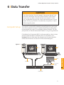
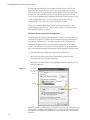
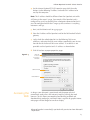
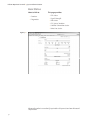
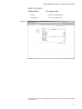
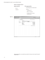
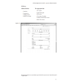
1
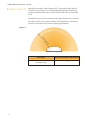
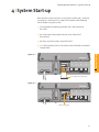
06504410100009010 Original User Manual IRIDIUM OPENPORT TERMINAL Alaska Region Research Vessel (ARRV) R/V Sikuliaq Marinette Marine Corporation Fincantieri Marine Group 1600 Ely Street Marinette, WI 54143 1 AUGUST 2012 RECORD OF CHANGES REVISION DATE DESCRIPTION OF CHANGE ‐ 8‐1‐12 INITIAL ISSUE BY RS FOREWORD THIS MANUAL IS INTENDED TO CLEARLY AND ACCURATELY REFLECT THE ACTUAL CONFIGURATION OF THE INSTALLED EQUIPMENT AND PROVIDE THE USER WITH THE NECESSARY INSTRUCTIONS TO SUCCESSFULLY OPERATE, MAINTAIN, AND TROUBLESHOOT ASSOCIATED EQUIPMENTS. THE MANUAL IS CONSTRUCTED AS FOLLOWS: INTRODUCTION SAFETY OVERVIEW SYSTEM STARTUP VOICE CALLS DATA TRANSFER SYSTEM ADMINISTRATION TROUBLESHOOTING Notice: Export Compliance Information This product is controlled by the export laws and regulations of the United States of America. The U.S. Government may restrict the export or re-export of this product to certain individuals and/or destinations. For further information, contact the U.S. Department of Commerce, Bureau of Industry and Security or visit www.bis.doc.gov. Disclaimer Every effort has been made to ensure the correctness and completeness of the material in this document. No company shall be liable for errors contained herein. The information in this document is subject to change without notice. No warranty of any kind is made with regard to this material, including, but not limited to, the implied warranties of merchantability and fitness for a particular purpose. I Contents 1 Introduction . . . . . . . . . . . . . . . . . . . . . . . . . . . . . . . . . . . . . . . . . . . . . . . . . 1-1 About this Manual . . . . . . . . . . . . . . . . . . . . . . . . . . . . . . . . . . . . . . . . . 1-1 Terms to Know . . . . . . . . . . . . . . . . . . . . . . . . . . . . . . . . . . . . . . . . . . . . . 1-1 Reference Documents . . . . . . . . . . . . . . . . . . . . . . . . . . . . . . . . . . . . . 1-1 2 Safety . . . . . . . . . . . . . . . . . . . . . . . . . . . . . . . . . . . . . . . . . . . . . . . . . . . . . . . .2-1 Electrical Shock Warning . . . . . . . . . . . . . . . . . . . . . . . . . . . . . . . . . . 2-1 Radiation Hazard . . . . . . . . . . . . . . . . . . . . . . . . . . . . . . . . . . . . . . . . . . 2-2 3 Overview . . . . . . . . . . . . . . . . . . . . . . . . . . . . . . . . . . . . . . . . . . . . . . . . . . . . 3-1 Iridium Satellite Communications . . . . . . . . . . . . . . . . . . . . . . . . . 3-1 OpenPort Terminal Components . . . . . . . . . . . . . . . . . . . . . . . . . . 3-1 Specifications . . . . . . . . . . . . . . . . . . . . . . . . . . . . . . . . . . . . . . . . . . . . . 3-1 4 System Start-up . . . . . . . . . . . . . . . . . . . . . . . . . . . . . . . . . . . . . . . . . . . . . . 4-1 SIM Validation . . . . . . . . . . . . . . . . . . . . . . . . . . . . . . . . . . . . . . . . . . . 4-2 Starting the System . . . . . . . . . . . . . . . . . . . . . . . . . . . . . . . . . . . . . . . 4-2 5 Voice Calls . . . . . . . . . . . . . . . . . . . . . . . . . . . . . . . . . . . . . . . . . . . . . . . . . . . 5-1 Voice Call from Handset . . . . . . . . . . . . . . . . . . . . . . . . . . . . . . . . . . . 5-1 Voice Call using Prepaid Card . . . . . . . . . . . . . . . . . . . . . . . . . . . . . . 5-2 Supplemental Services . . . . . . . . . . . . . . . . . . . . . . . . . . . . . . . . . . . . 5-2 PIN Feature . . . . . . . . . . . . . . . . . . . . . . . . . . . . . . . . . . . . . . . . . . . . .5-2 Call Barring . . . . . . . . . . . . . . . . . . . . . . . . . . . . . . . . . . . . . . . . . . . . .5-2 Call Forwarding . . . . . . . . . . . . . . . . . . . . . . . . . . . . . . . . . . . . . . . . .5-3 Voice Mail . . . . . . . . . . . . . . . . . . . . . . . . . . . . . . . . . . . . . . . . . . . . . . 5-4 6 Data Transfer . . . . . . . . . . . . . . . . . . . . . . . . . . . . . . . . . . . . . . . . . . . . . . . . 6-1 Computer Set-up . . . . . . . . . . . . . . . . . . . . . . . . . . . . . . . . . . . . . . . . . 6-1 PC & Network Configuration . . . . . . . . . . . . . . . . . . . . . . . . . . . . . . 6-2 Accessing the Internet . . . . . . . . . . . . . . . . . . . . . . . . . . . . . . . . . . . . 6-5 7 System Administration . . . . . . . . . . . . . . . . . . . . . . . . . . . . . . . . . . . . . . 7-1 ISU Web Pages . . . . . . . . . . . . . . . . . . . . . . . . . . . . . . . . . . . . . . . . . . . . 7-1 Configuring the System . . . . . . . . . . . . . . . . . . . . . . . . . . . . . . . . . . . 7-5 Software Upgrade . . . . . . . . . . . . . . . . . . . . . . . . . . . . . . . . . . . . . . . 7-15 8 Troubleshooting . . . . . . . . . . . . . . . . . . . . . . . . . . . . . . . . . . . . . . . . . . . . . 8-1 Below Decks Equipment (BDE) LEDs . . . . . . . . . . . . . . . . . . . . . . . .8-1 Access Denied . . . . . . . . . . . . . . . . . . . . . . . . . . . . . . . . . . . . . . . . . . . . 8-3 Appendix A: Approvals . . . . . . . . . . . . . . . . . . . . . . . . . . . . . . . . . . . . . . A-1 Appendix B: Specifications . . . . . . . . . . . . . . . . . . . . . . . . . . . . . . . . . . B-1 1 I Introduction Thank you for purchasing the state of the art Iridium OpenPort Terminal. Iridium is the only provider of truly global satellite voice and data communications solutions with complete coverage of the entire earth including oceans, airways and even polar regions. The Iridium OpenPort Terminal delivers reliable, secure, real-time, simultaneous high quality voice and up to 128kbit/s data connection to the Iridium satellite network from any point on the globe. About This Manual This manual provides you with complete information on the use of the OpenPort Terminal. This includes the following: • • • • • Terms to Know Starting the system How to make and receive voice calls How to transfer data across the Internet System Administration Troubleshooting ADE: Above Decks Equipment, the radiating unit. BDE: Below Decks Equipment, the user interface unit. ISU: Iridium Subscriber Unit, The ADE and BDE together. POTS: Plain Old Telephony System SIM: Subscriber Identity Module PSU: Power Supply Unit Provisioned: A term used to indicate the SIM card is activated for voice and data connection. This can only be done by the Service Provider. 1 Introduction Iridium OpenPort Terminal I 1 Introduction 1.2 Iridium OpenPort Terminal I 2 Safety 2 I Safety The ADE and the BDE should be installed by a qualified professional technician trained in the installation of marine electronics and antennas. Failure to comply with these precautions or with specific warnings on the equipment or in this manual violates the safety standards of the design, manufacture and intended use of this equipment. Follow all safety precautions carefully. Improper installation may result in injury or inability of the equipment to function properly. Only a qualified professional technician trained in the installation of marine electronics and antennas should remove the installation cover on the BDE. 2 Safety Warnings Iridium Satellite LLC disclaims all liability for the customer’s failure to comply with these requirements and improper installation. ! WARNING! The Below Decks Equipment (BDE) contains low voltage that may cause serious injury if opened or not grounded. Ensure the unit is properly grounded before operation and do not, under any conditions, open or dismantle the BDE. ! CAUTION! The Above Decks Equipment (ADE) transmits radio frequency (RF) that is potentially harmful. When the system power is ON keep all personnel a minimum of 1.0 m (3.3 ft.) from the antenna (see Radiation Hazard). Figure 2 I 1 POWER STATUS SIGNAL GPS SIM on / off Installation cover data voice 1 SIM cover 2.1 voice 2 Iridium OpenPort Terminal I 2 Safety Radiation Hazard Potentially hazardous radio frequency (RF) is transmitted from the ADE. To avoid risk to personnel it is recommended people keep the following distances between themselves and the antenna when the system power is ON. Personnel must maintain a minimum separation distance of 1m from the unit and installers must place the Above Deck Equipment transmitter in a manner to maintain this minimum spacing requirement. Figure 2 I 2 ion Haza t a i d rd Ra 1.0 m (3 f .3 t.) 2.2 Description Minimum Distance from Antenna within 0° - 180° of the antenna elevation range 1.0 m (3.3 ft.) Iridium OpenPort Terminal I 3 Overview 3 I Overview Iridium Satellite Communications Iridium’s constellation consists of 66 low-earth orbiting (LEO), crosslinked satellites operating as a fully meshed network and supported by multiple in-orbit spares. Iridium has gateways in Arizona and Hawaii and additional telemetry, tracking and control facilities in Alaska, Canada and Norway. It is the largest commercial satellite constellation in the world. 3 Overview Figure 3 I 1 OpenPort Terminal Above Decks Equipment Components Figure 3 I 2 1 1. Above Decks Equipment (ADE) The Above Decks Equipment (ADE) provides the communication connection between the BDE and Iridium’s satellites. The ADE will automatically locate and track Iridium satellites overhead. 3.1 Iridium OpenPort Terminal I 3 Overview Below Decks Equipment Figure 3 I 3 2 4 power status signal GPS ® SIM off / on 3 data voice 1 voice 2 voice 3 6 SIM card, reset button and on/off switch are located behind panel 2. Below Decks Equipment: The Below Decks Equipment (BDE) is the appliance to which you connect your telephones and computers. It is capable of handling three POTS/RJ11 telephone handsets and one Ethernet data connection. 3. ADE / BDE Cable: The cable connects the ADE to the BDE. It is shielded and has a waterproof connection for the ADE. 4. AC Power Supply Unit: The AC Power Supply Unit (PSU) provides power to the BDE. 5. POTS Handsets (see page 5.2): Two handsets are provided with your OpenPort Equipment: a Standard Phone for installation on the bridge, and one Crew Phone, designed for quick access to Iridium Crew Calling services. 6. SIM: The SIM card validates the system at start-up, allows connection to the Iridium network and provisions the appropriate phone and data lines. Specifications 3.2 See Appendix B for product specifications. Iridium OpenPort Terminal I 4 System Start-up 4 I System Start-up Now that the system has been set up by the installer and is ready for use when it is turned ON it is important to conduct the following checks before using the system: 1. Is the equipment properly grounded and is there power to the units? 2. Are all personnel the proper distance away from the RF hazard zone? 3. Are there any obstructions around the ADE? 4. Is a valid OpenPort SIM card installed in the SIM holder and locked into position? power status signal GPS 4 System Start-up Figure 4 I 1 ® data voice 1 voice 2 voice 3 Insert OpenPort SIM card Figure 4 I 2 power status signal GPS ® data voice 1 voice 2 voice 3 Slide locking tab 4.1 Iridium OpenPort Terminal I 4 System Start-up SIM Validation In order to access the Iridium network the BDE must have a valid SIM installed. The number of voice lines available is set when your Service Provider provisions (enables) the SIM card. For example: There are three phone lines available but you choose to only provision one of them. Upon system activation only one phone line will be available. Your service provider is the only party capable of provisoning voice and data lines. Contact your service provider to provision or remove phone and data lines. Once the service provider has provisioned the appropriate line(s) this information is downloaded to the OpenPort Terminal the next time you access the network. Note: If the SIM card is removed or unlocked any voice or data calls will be terminated immediately. The SIM must be reinserted and locked into position using the locking mechanism on the SIM card holder, then the unit must be switched off and back on again to be reactivated. Starting the System 1. On the BDE, press the on/off switch located under the SIM cover. The system authentication will be conducted and the ADE will establish a link with an Iridium satellite. The on/off indicator will illuminate green. ON/OFF indicator Figure 4 I 3 power status signal GPS ® data voice 1 voice 2 voice 3 on/off switch Note: If the ON/OFF indicator is not green see Section 8, Troubleshooting the BDE. 2. Turn on your computers or network. 4.2 Iridium OpenPort Terminal I 5 Voice Calls 5 I Voice Calls The BDE provides three connectors for POTS handsets, which can be used simultaneously. In order to make or receive a phone call you must have a valid SIM installed in the BDE. The BDE will indicate (illuminate green) the lines that have been provisioned. Provisioned lines will illuminate green Figure 5 I 1 power status signal GPS ® data voice 1 voice 2 voice 3 Note: If none of the data or voice LEDs are green then it may be that no services have been provisioned. If they are amber, you may be denied access to the Iridium network. See Section 8, Troubleshooting the BDE. Voice Call from Handset A voice line can be configured to one of two line types, A crew line which must use an OpenPort Crew handset, or a Standard line. Follow these steps when calling from a Standard line: 5 Voice Calls The telephone interfaces can be configured to set the phone tones (ring, dial and busy signal) to a specific country (see Figure 7.9). 1. Connect the handset to the BDE. 2. Type in the country code, the phone number required, ending with the # key. For example: country code + local phone number + # pound Key 5.1 2.2 Iridium OpenPort Terminal I 5 Voice Calls Figure 5 I 2 ;d[V[g_AbW`Badf ;d[V[g_AbW`Badf F? F? 5dWiBZa`W 6;3>;@9;@EFDG5F;A@E 5SbfS[`, 06[S^Uag`fdkUaVWbZa`W`g_TWdfZW` BdWee 0;XB;@[eW`ST^WV,6[S^&V[Y[fB;@Uag`fdk UaVWbZa`W`g_TWdfZW`bdWee B^WSeWdWXWdfakagd;d[V[g_AbW`Badf_S`gS^ Xad[`Xad_Sf[a`a`bdaYdS__[`YSVV[f[a`S^ W`ZS`UWVXWSfgdWeegUZSeW`ST^[`YSB;@fa bdWhW`fg`SgfZad[lWVUS^^[`Y ;d[V[g_9a5ZSf6[S^[`Y;`efdgUf[a`eXad ;d[V[g_AbW`Badf # BdWee>S`YgSYW $ 7`fWdbZa`W`g_TWdUUBZa`W@g_TWd % IS[fXadha[UWbda_bffaW`fWdB;@ & 7`fWdB;@S`ViS[fXadUa``WUf[a` BdWee^S`YgSYWTgffa`fi[UWXadSUUag`fTS^S`UW 5dWi5S^^[`Y, IZW`ge[`Y;d[V[g_9a5ZSfbdWbS[VUS^^[`YUSdVe b^WSeWdWXWdWfafZW[`efdgUf[a`e^aUSfWVa`fZW TSU]aXfZWUSdV 7`Y^[eZ 1 2 $ 345 ABC 3 DEF 4 GHI 5 KLM 6 MNO 7PQRS 8 TUV 9WXYZ 0 # * 345 ABC 3 DEF 4 GHI 5 KLM 6 MNO 7PQRS 8 TUV 9WXYZ 0 # MUTE HA> SPKR SPKR Standard Handset Supplemental Services $2 * MUTE HA> REDIAL Voice Call Using GoChat Card FSYS^aY 1 Crew Handset Iridium OpenPort uses a dedicated phone for crew calling which requires an Iridium GoChat card (see your service provider for information on how to purchase an Iridium GoChat card). Placing a call requires pressing a dedicated speed-dial button, then entering the phone number followed by the #. At the prompt enter your scratch card pin number. Additional instructions are listed on each crew phone. PIN Feature The PIN feature is only available for a “Standard” line. • To disable PIN, dial *70*<PIN># • To enable PIN, dial *71*<PIN># • To change PIN, dial *72*<old PIN>*<new PIN>*<new PIN># • To change AND enable PIN, dial *73*<old PIN>*<new PIN>*<new PIN># If PIN is enabled, a user making call will need to enter PIN before other dialed digits; e.g., • <PIN><phone number># Regardless if PIN is enabled or not, PIN is NEVER required for emergency calls and supplementary service code (including PIN feature) dialing. Call Barring Call Barring is supported to block all incoming or all outgoing calls. A 4digit password is used for all Call Barring operations (activation/ deactivation). 5.2 Iridium OpenPort Terminal I 5 Voice Calls Outgoing call barring Note: There is only one password for Standard and Supplemental Service (default password: 0000). • Activation: dial *33* <password> # • Deactivation: dial *34* <password> # • Check Status: dial *33# [A prompt will be played indicating if Outgoing call barring is enabled.] Incoming call barring • Activation: dial *35* <password> # • Deactivation: dial *36* <password> # • Check Status: dial *35# [A prompt will be played indicating if Incoming call barring is enabled.] Call Forwarding Iridium OpenPort supports Call Forward Unconditional, Call Forward Busy, Call Forward No Answer, and Call Forward Not Reachable. The default number for call forwarding is the Voice Mail number of the phone line. Call Forward Unconditional Forward all incoming calls to another number. All calls will be forwarded to the registered number. • Register: dial *21* <number> # [Specifies the phone number for Call Forward Unconditional.] • Activation: dial *21# • Deactivation: dial *22# • Check Status: dial *23# [A voice prompt will be played indicating if Call Forward Unconditional is enabled and the number that is registered to forward calls.] Call Forward Busy Forward incoming calls if the phone line is currently in a call. • Register: dial *67* <number> # [Specifies the phone number for Call Forward Busy.] • Activation: dial *67# • Deactivation: dial *68# 5.3 Iridium OpenPort Terminal I 5 Voice Calls • Check Status: dial *69# [A voice prompt will be played indicating if Call Forward Busy is enabled and the number that is registered to forward calls.] Call Forward No Answer Forwards incoming calls if the phone line does not answer in a specified amount of time. • Register: dial *61* <number>*<timeout> # [Specifies the number and timeout (in seconds) for Call Forward No Answer. If an incoming call is not answered by the unit in the time specified in the registration, the call is forwarded.] • Activation: dial *61# • Deactivation: dial *62# • Check Status: dial *63# [A voice prompt will be played indicating if Call Forward No Answer is enabled and the number that is registered to forward calls.] Call Forward Not Reachable Forwards incoming calls after no response in reaching the Iridium OpenPort unit (e.g., unit is turned off). • Register: dial *24* <number> # [Specifies the number to forward to if there is no response in reaching the unit.] • Activation: dial *25# • Deactivation: dial *26# • Check Status: dial *27# [A voice prompt will be played indicating if Call Forward Not Reachable is enabled and the number that is registered to forward calls.] Call Forwarding Precedence Call Forward Unconditional takes precedence, then Call Forward Busy, then Call Forward Not Reachable, then Call Forward No Answer. When a status check command is sent, only the highest priority active Call Forwarding is reported back. Cancel all call forwarding – Cancels any and all types of call forwarding, including sending a call to Voice Mail. *002# - This command deactivates all call forwarding. 5.4 Iridium OpenPort Terminal I 5 Voice Calls Voice Mail If you have subscribed to Voice Mail then you will be notified that a Voice Mail is waiting for you in three possible ways: • Interrupted “stuttering” dial tone whenever the user picks up the phone to make an outgoing call. Activation: dial *86# • Message Waiting LED on the phone (if using the Iridium Standard Handset). • On ISU Status Page (see Section 7, System Administration) One Voice Mail box is provisioned for each subscriber line provisioned as a Standard line. No Voice Mail box is provided for a Crew line. To access your Voice Mail box a user can dial *86#. The user will be able to access the Voice Mail system to check and retrieve Voice Mail messages in the language settings of the subscriber line. On an Iridium Standard Handset the user can retrieve the Voice Mail by pressing the red Voice Mail Notification button at the bottom of the phone. The Iridium OpenPort Voice Mail System can also be reached by dialing 881663790000 from any phone line anywhere. When calling from other than a subscriber line the Voice Mail system will default to English and prompt for the subscriber line phone number to access the subscriber’s Voice Mail. 5.5 Notes 5.6 Iridium OpenPort Terminal I 6 Data Transfer 6 I Data Transfer CAUTION The Iridium OpenPort Terminal supports “connect on demand” and will make a connection across the Iridium network if a data device tries to access an address outside the local area network. It is the user’s responsibility to secure the system from outside access. Ensure proper security (e.g.: firewall, virus protection, encryption) is in place before using the system. Computer Set-up The internal structure of the computer network depends on your needs. The Iridium OpenPort Terminal is capable of handling everything from the connection of a single PC to a complete Ethernet network. The data port provides an Ethernet connection of 10BaseT using an RJ45 connector. If the Below Decks Equipment (BDE) is to be connected to a down-stream port of an Ethernet hub or switch then the user will need to use a crossover Ethernet cable. Again, the data port must be provisioned to connect to the Internet. The data LED will be illuminated green. Figure 6 I 1 BDE baiWd efSfge e[Y`S^ Ethernet 9BE E;? a`!aXX VSfS ha[UW# ha[UW$ ha[UW% Crossover Cable HUB Switch 6.1 6 Data Transfer PC PC Iridium OpenPort Terminal I 6 Data Transfer PC & Network Configuration For a single PC • Connect directly to the data port of the BDE • Use a standard Ethernet cable • Configure PC for static configuration ( for more details see Windows® PC Set-up for Static Configuration) For multiple PCs • Connect the switch/hub/router to the data port on the BDE using a crossover Ethernet cable. • Connect the PCs to the Ethernet switch, hub or router (Note: these multiple devices will be sharing the same satellite connection over the Iridium network, the more devices connected the smaller the share of the connection.) • Depending on how your ship-side LAN is configured you may or may not want the Iridium OpenPort Terminal to act as a DHCP server and to perform DNS forwarding (see the following section to change). Configuration of LAN Settings The Iridium OpenPort Terminal allows you to configure the following LAN settings, via the web pages when logged on as ‘admin’. These settings include: • IP Address • Subnet Mask • DHCP Server and IP Address Range to Use • DNS Forwarding IP Address This is the IP address of the Iridium OpenPort Terminal as seen from the vessel. The factory default is 192.168.0.1. You should not change this default unless there is already LAN equipment on the vessel, in which case you must set this to an unused IP address of the ship-side LAN. Subnet Mask This defines the subnet used on the vessel. The factory default is 255.255.255.0. You should only change this default if you change the IP address of the Iridium OpenPort Terminal. All network devices must use the same subnet in order to communicate with one another. Windows and Windows XP are either registered trademarks or trademarks of Microsoft Corporation in the United States and/or other countries. 6.2 Iridium OpenPort Terminal I 6 Data Transfer Dynamic Host Configuration Protocol (DHCP) server This automatically provides unique IP addresses and appropriate configuration parameters to each network device connected to the Iridium OpenPort Terminal. In the current configuration, DHCP is disabled. Note: While DHCP is disabled, devices connected to the Iridium OpenPort Terminal will need to have their network settings manually configured. There must only be one DHCP server on any network segment. Please see insert on “how to configure network connections manually with Windows®.” DHCP IP Address minimum and maximum This sets the range of IP addresses for the DHCP server to use. The factory default is 192.168.0.2 to 192.168.0.254. The range specifies the maximum number of devices on the network. Both the maximum and minimum value must be in the same subnet. Domain Name System (DNS) forwarding DNS is used to convert network names (such as www.google.com) into the IP addresses needed to connect to the device. The factory default is disabled. The Iridium OpenPort Terminal acts as a switching station so that it automatically forwards DNS requests to the appropriate DNS server. Once you change the LAN configuration and press the ‘Update IP Configuration’ button the Iridium OpenPort Terminal will reboot to apply the configuration changes - this will drop any calls. Once the Iridium OpenPort Terminal has rebooted any connected network devices may take up to 10 minutes to automatically obtain new settings. During this switch over time the network devices may not be able to communicate with the Iridium OpenPort Terminal or/and duplicate IP address settings can occur. If you change the LAN settings it is advisable to reboot any attached devices to avoid this issue Note: The LAN Settings can be reset to the factory defaults using the reset switch on the BDE. Windows and Windows XP are either registered trademarks or trademarks of Microsoft Corporation in the United States and/or other countries. 6.3 Iridium OpenPort Terminal I 6 Data Transfer Exactly how you configure the network clients on the vessel will vary depending on the operating system. Refer to your operating system manual or technical support organization to obtain the exact details to achieve this. You should normally use the Iridium OpenPort Terminal DHCP server to automatically configure the correct client settings. If you use this option the clients must be setup to obtain their settings automatically. This is the easiest way to setup a network. If you use a static configuration you must ensure that the ISU is the default gateway, that the ISU is on the same subnet as all devices and each network address is unique. Windows® PC Set-up for Static Configuration Depending on the needs of your computer network, it may be necessary to statically assign an IP address to the computer directly connected to the Iridium OpenPort unit. The following steps cover a Windows XP® configuration however they can generally be applied to all Windows® setups. For additional assistance in configuring your desktop computer for a static connection please contact your local computer administrator. 1. Open Network Connections located in the Control Panel. 2. Locate the icon for the Local Area Connection connected to the OpenPort unit and right-click Properties. 3. From the list of connections used, highlight Internet Protocol (TCP/IP) and click Properties Figure 6 I 2 Local Area Connection Properties window TCP/IP Properties 6.4 Microsoft product screenshot(s) reprinted with permission from Microsoft Corporation. Windows and Windows XP are either registered trademarks or trademarks of Microsoft Corporation in the United States and/or other countries. Iridium OpenPort Terminal I 6 Data Transfer 4. On the Internet Protocol (TCP/IP) Properties page, click the radio button Use the following IP address: and enter an IP address to be used by this computer. Note: This IP address should be different from the OpenPort unit while still being in the same IP range. For example, if the OpenPort unit is configured as 192.168.0.1 (default), then a computer connected to the ISU must be configured within the IP range 192.168.0.x where x is anything between 2 and 254. 5. Next, set the Subnet mask: to 255.255.255.0 6. Enter the IP address of the OpenPort unit for the field marked Default gateway. 7. Lastly, check the radio button for Use the following DNS server addresses: and enter the DNS server address provided by your Service Provider for the Preferred DNS server address. If an address is not provided use the OpenPort unit’s IP address as shown below. 8. Click OK to close any open properties pages. Figure 6 I 3 Internet Protocol Properties window Subnet mask Radio button Accessing the Web As long as your data port is provisioned and the proper physical connections made, access the Internet simply by starting your web browser. The ISU allows you complete functionality to upload and download data, web pages, and email. Note: Large files or graphic intense web pages will take longer to transfer or display. Microsoft product screenshot(s) reprinted with permission from Microsoft Corporation. 6.5 Notes 6.6 Iridium OpenPort Terminal I 7 System Administration 7 I System Administration ISU Web Pages Diagnostics There are two levels of diagnostic information available, basic and administrator. The user can access any web page with the “Basic” heading. Configuring the system and full diagnostics can only be done by the System Administrator and requires a login password. The following Basic diagnostics and configuration capability is available to the user. To access the Iridium OpenPort Terminal Web Pages: 1. Connect a PC to the data port on the BDE 2. Open the web browser and in the web browser address window, type: http://192.168.0.1. Note: The default IP address is assigned to the Iridium Openport Terminal at the factory. The IP address can be changed if there are multiple ISU’s at a single site. If this has been done then type in the new IP address. To reset the IP address back to the default (192.168.0.1), press the network reset button on the BDE. 3. Select the appropriate link: • Basic Status • Basic Counters • Basic Diagnostics 7 System Administration Note: The information displayed on the web pages is not dynamically updated. To update the information, refresh the web page from your browser. 7.1 Iridium OpenPort Terminal I 7 System Administration Basic Status Select to link to: • Counters • Diagnostics This page provides: • LED status • Signal Strength • SIM status • GPS status, location • Satellite Connection status • Voice Line status Figure 7 I 1 Microsoft product screenshot(s) reprinted with permission from Microsoft Corporation. 7.2 Iridium OpenPort Terminal I 7 System Administration Basic Counters Select to link to: This page provides: • Status • Voice Call information • Diagnostics • Data Use information Figure 7 I 2 Microsoft product screenshot(s) reprinted with permission from Microsoft Corporation. 7.3 Iridium OpenPort Terminal I 7 System Administration Basic Diagnostics Select to link to: • Status • Counters This page provides: • Useful diagnostic information such as: • Equipment ID • MAC & IP address • Hardware & Firmware revision level Figure 7 I 3 Microsoft product screenshot(s) reprinted with permission from Microsoft Corporation. 7.4 Iridium OpenPort Terminal I 7 System Administration Configuring the System Configuring the system and full diagnostics can only be done by the System Administrator and requires a login password. The default user name and password is “admin”. Change the password if desired. To access the ISU Web Pages: 1. Connect a PC to the data port on the BDE 2. Open the web browser and in the web browser address window, type: http://192.168.0.1. Note: The default IP address is assigned to the ISU at the factory. The IP address can be changed if there are multiple ISU’s at a single site. If this has been done then type in the new IP address. To reset the IP address back to the default (192.168.0.1), press the network reset button on the BDE. Figure 7 I 4 power status signal GPS ® data voice 1 voice 2 voice 3 Reset button 3. Select “Login” for administrator level diagnostics. Type in the user name and password specified by Iridium. Call your Service Provider if login fails. 7.5 Iridium OpenPort Terminal I 7 System Administration 4. Select the appropriate link: Note: The information displayed on the web pages is not dynamically updated. To update the information, refresh the web page from you browser. Select to link to: • Status • Counters • Diagnostics Figure 7 I 5 Microsoft product screenshot(s) reprinted with permission from Microsoft Corporation. 7.6 Iridium OpenPort Terminal I 7 System Administration Status Select to link to: • Counters • Diagnostics • Configuration • Admin Password This page provides: • LED status • Signal Strength • SIM status • GPS status, location • Satellite Connection status • Voice Line status Figure 7 I 6 Microsoft product screenshot(s) reprinted with permission from Microsoft Corporation. 7.7 Iridium OpenPort Terminal I 7 System Administration Counters Select to link to: This page provides: • Status • Voice Call information • Diagnostics • Configuration • Admin Password • Data Use information Figure 7 I 7 Microsoft product screenshot(s) reprinted with permission from Microsoft Corporation. 7.8 Iridium OpenPort Terminal I 7 System Administration Diagnostics Select to link to: • Status • Counters • Configuration • Admin Password This page provides: • Useful diagnostic information such as: • Equipment ID • MAC & IP address • Hardware & Firmware revision level Figure 7 I 8 Microsoft product screenshot(s) reprinted with permission from Microsoft Corporation. 7.9 Iridium OpenPort Terminal I 7 System Administration Configuration Select to link to: This page provides: • Status • LAN IP configuration • Counters • Port forwarding configuration • Diagnostics • Admin Password • Localization configuration Figure 7 I 9 Microsoft product screenshot(s) reprinted with permission from Microsoft Corporation. 7.10 Iridium OpenPort Terminal I 7 System Administration Port Forwarding Port forwarding is taking a port on the outside of the OpenPort, such as port 80 (typically used for web servers) and passing it to another machine on the internal network, on the same port (80). Port redirection is taking a port on the outside, i.e. 80, and passing it to another machine on the internal network, but on a different port, i.e. 8080. Before beginning the user will need to know what port they wish to forward from outside the Iridium OpenPort, to the inner network, and whether or not they need to ‘redirect’ the port as well. They will also need to know if the data will be TCP or UDP. 1. Click ‘Add Rule’ (see Figure 7.9). An administration page will open (shown below) Figure 7 I 10 Microsoft product screenshot(s) reprinted with permission from Microsoft Corporation. 7.11 Iridium OpenPort Terminal I 7 System Administration 2. Enter / Select the following: • The external port number to forward to the inside. • The internal port number which will be receiving the data. Note: If you are redirecting as well, this number will be different than the external port number. • The IP address of the computer which is receiving the data. Note: This will need to be on the same subnet as the OpenPort ISU. • The protocol for the data: TCP or UDP. Figure 7 I 11 3. Click OK. The updated configuration page with the newly added rule is displayed. Microsoft product screenshot(s) reprinted with permission from Microsoft Corporation. 7.12 Iridium OpenPort Terminal I 7 System Administration Figure 7 I 12 4. Add additional rules as needed. Note: Rules can be turned on/off without having to be deleted. Figure 7 I 13 Microsoft product screenshot(s) reprinted with permission from Microsoft Corporation. 7.13 Iridium OpenPort Terminal I 7 System Administration Admin Password Change To change the Admin Password enter the current password (the default password is “admin”) followed by your new password. Enter the new password a second time and click the Change Password button. Your new password is now active. Figure 7 I 14 Figure 7 I 15 Microsoft product screenshot(s) reprinted with permission from Microsoft Corporation. 7.14 Iridium OpenPort Terminal I 7 System Administration Software Upgrade To upgrade the software you need: • A Windows®-based PC • Standard Ethernet cable • OpenPort Terminal Upgrade Tool executable software Follow these steps to upgrade the software: 1. Connect PC to OpenPort data port with a standard Ethernet cable. 2. Open a browser and verify connectivity with the OpenPort terminal by navigating to 192.168.0.1, which is the default IP address assigned to all OpenPort terminals at the factory. If the default has been changed, enter the new IP address of the terminal. 3. If you see the OpenPort status web page, proceed to step 4. Otherwise, you may need to configure TCP/IP properties in your computer – please refer to Section 4.12 for detailed instructions on computer setup. 4. Double click the OpenPort Upgrade tool executable. The following window will appear. Enter the IP address of the OpenPort terminal. Figure 7 I 17 Microsoft product screenshot(s) reprinted with permission from Microsoft Corporation. 7.15 Iridium OpenPort Terminal I 7 System Administration 5. Click the “Upgrade” button to start the upgrade process. The progress bar will move from 0 to 100 as the upgrade takes place. Once the upgrade process is complete, the message “Upgrade successful. Power cycle unit” will appear. Figure 5 I 19 6. Turn the unit off for 10 seconds and then turn it on again. 7. To verify that the new software version was installed, connect to the OpenPort Admin web page (see step 2), and click “diagnostics”. The software version is displayed on this page. Microsoft product screenshot(s) reprinted with permission from Microsoft Corporation. 7.16 8 I Troubleshooting There are two main sources of information for troubleshooting: 1. The ISU Web Pages (as detailed in Section 7) 2. The LEDs on the BDE LED Off power No power supplied to BDE status Idle: connected to the Iridium network but no traffic signal Not Used GPS Not Used data Data port not provisioned. voice 1 Voice port 1 not provisioned. * Or handset off hook. voice 2 Voice port 2 not provisioned. * Or handset off hook. voice 3 Voice port 3 not provisioned. * Or handset off hook. Green Green Flashing Power Not Used supplied to BDE and BDE switched on. Power is being passed to ADE. Active: Voice or Not Used data is being transferred to/ from the Iridium network Strong Not Used network signal detected GPS signal available to ADE Data port provisioned for use. Not Used Flashing when data call in progress Amber Red Red Flashing Power supplied Not Used to BDE, BDE switched off Not Used Standby: not connected to the Iridium network. BDE cannot communicate with ADE – check connections. Not Used Weak network No signal detected network signal detected. Not Used No GPS signal Access to network denied - see Web Page for details. Voice port 1 Incoming Access to provisioned for call (ringing) network use. or call in denied - see progress. Web Page for details. Voice port 2 Incoming Access to provisioned for call (ringing) network use. or call in denied - see progress. Web Page for details. Voice port 3 Incoming Access to provisioned for call (ringing) network use. or call in denied - see progress. Web Page for details. Not Used Not Used SIM problem Not Used SIM problem Not Used SIM problem Not Used SIM problem Not Used * The BDE does not know what services are provisioned until it has connected to the network so this LED will be off at initial power up. 8.1 8 Troubleshooting Iridium OpenPort Terminal I 8 Troubleshooting Iridium OpenPort Terminal I 8 Troubleshooting Suggested actions for the following fault conditions: LED Color power Off power Amber status Reason No power supplied to BDE Suggested Action Get a qualified person to check the power being supplied to the BDE, it should be between 11 – 32VDC at the input to the BDE and capable of providing up to 50W. Power supplied to BDE, BDE Remove the SIM cover and ensure that the on/off switched off switch is in the on positions. With this switch in the on position the LED should be green. If the switch is on and this LED remains amber then call your service provider for assistance. Red BDE cannot communicate Flashing with ADE – check connections. Get a qualified person to check the connection between the BDE and ADE, this should include the connections at the BDE and ADE and the entire cable between them. signal Red No network signal detected. It is valid for this LED to go red for short periods of time but it should not remain red. If it remains red it implies that there is a problem with the equipment. Please call your service provider and report all the information you can see on the web pages as well as the LED colors. GPS Red No GPS signal You may be in an area where a GPS signal cannot be received, if the vessel moves and the problem persists then contact your service provider and report that internal GPS has failed. data Amber Access to network denied see Web Page for details. Access to the Iridium network has been denied, there are a number of reasons for this below for details (see Access Denied table, page 9.3). data Red SIM problem Check SIM inserted correctly and SIM lock on SIM holder pushed across. Check you have a valid OpenPort SIM. voice Amber Access to network denied see Web Page for details. Access to the Iridium network has been denied, there are a number of reasons for this below for details (see Access Denied table, page 9.3). voice Red SIM problem Check SIM inserted correctly and SIM lock on SIM holder pushed across. Check you have a valid OpenPort SIM. 8.2 Iridium OpenPort Terminal I 8 Troubleshooting Access Denied Denial of access will be indicated by the voice and data LEDs on the BDE illuminating Amber. Access to the Iridium network may be denied for a number of reasons. The following items contain information that you may be asked to provide when contacting your service provider. Reason Suggested Action TMSI invalid Unit will automatically try to access the network using the IMSI. IMSI invalid Call service provider. Authentication Failure Check SIM status on Status web page, check using a valid SIM card. If all ok call service provider. IMEI Blacklisted Call service provider Indeterminable Location Check GPS LED on BDE. If LED is green, check GPS status on web page. Contact Service Provider with this information and denial information. Restricted Area Wait until move into different geographical area 8.3 Notes 8.4 Iridium OpenPort Terminal I Appendix A Approvals FCC Declaration for 9701 This equipment has been tested and found to comply with the limits for a Class B digital device, pursuant to Part 15 of the FCC Rules. These limits are designed to provide reasonable protection against harmful interference in a residential installation. This equipment generates, uses and can radiate radio frequency energy and, if not installed and used in accordance with the instructions, may cause harmful interference to radio communications. However, there is no guarantee that interference will not occur in a particular installation. If this equipment does cause harmful interference to radio or television reception, which can be determined by turning the equipment Off and On, the user is encouraged to try to correct the interference by one or more of the following measures: • Reorient or relocate the receiving antenna. • Increase the separation between the equipment and receiver. • Connect the equipment into an outlet on a circuit different from that to which the receiver is connected. • Consult the dealer or an experienced radio/TV technician for help. Modifications to this device not expressly approved by Iridium Satellite LLC may void authority granted under the rules of the Federal Communications Commission to operate this device. Industry Canada This product is compliant with Industry Canada RSS-102 for RF Exposure. The 9701 BDE is a Class B digital apparatus and complies with Canadian ICES-003. Cet appareil numérique de la classe B est conforme à la norme NMB-003 du Canada. A.1 Iridium Openport Terminal I Appendix A - Approvals FCC Declaration of Conformity A.2 Iridium Openport Terminal I Appendix A - Approvals EU Declaration of Conformity A.3 Iridium Openport Terminal I Appendix B - Specifications RF Performance TX 1616 to 1626.5 MHz RX 1616 to 1626.5 MHz FDMA spacing 41.67 KHz TDMA timing 8.3 mS slot in a 90 mS window Channels available 64 channels 1 ch (voice) 1.1 watts average power EIRP 64 ch (max data rate) 6 watts average power Modulation Voice/Data QPSK Type 6 dual element azimuthal array and 1 zenith element, electronically switched and phase steered Polorization RHCP Gain +8 dB Beam width hemispheric coverage (60° per element) Steering automatic solid state Coverage horizon to horizon Ship’s Motion provides useful link margin up to roll = 20° Frequency of operation Channelization Antenna Power Requirements Main Power (AC) DC input (power module) Voltage 100-240 V Frequency 50/60 Hz Output Power 100 W (24 Volts @ 4.2 Amps max) DC input voltage 11 to 32 VDC Power in stand-by 18 watts Power during call 22 watts Power during data 31 watts Environmental Specs ADE (Above Deck Equip.) B.1 Exposure type RF-transparent dome-shaped cover and metal base Temperature range -30 to +70 deg. Celsius Relative Humidity 0 to 93% RH Precipitation meets IPX6 (low pressure continuous spray) Iridium Openport Terminal I Appendix B - Specifications Environmental Specs (cont’d) ADE (Above Deck Equip.) BDE (Below Deck Equip.) Wind in excess of 100 mph with proper mounting (see 4-5 of Installation Manual) Exposure type IP33 compliant (use inside controlled environment ) Temperature Range 0 to +50 deg. Celsius Physical Description ADE BDE Power module Interconnection Cable Diameter 57.0 cm Height 23.0 cm Weight 11.0 kg Mounting mounting M10 bolts on flange (~20 cm diameter) connected to pole Length 25.0 cm Width 19.0 cm Height 5.5 cm Weight 1.35 kg Mounting indoor, flat, vertical wall (supports BDE weight) Length 14.0 cm Width 5.9 cm Height 3.5 cm Weight < 0.5 lb Length (1) 45m Length (2) 70m (optional) User Interfaces ADE BDE BDE Connector Bulgin Buccaneer IP68 (9-pole fixed plug) SIM Card Furnished by Iridium Service Provider Data 10 baseT Voice 1 RJ-11 (2 wire) / POTS Voice 2 RJ-11 (2 wire) / POTS Voice 3 RJ-11 (2 wire) / POTS ADE Connector RJ-45 (proprietary) B.2 Iridium OpenPort Terminal I Comments Your comments and suggestions are welcome and greatly appreciated. They help us develop superior products for demanding professionals like you. For additional information about Iridium products and services, please contact Iridium as follows: By Telephone: Toll Free Number from USA: +1-866-947-4348 Local or International Number: +1-480-752-5155 By E-mail: [email protected] By Mail: Iridium Satellite LLC Attn.: Customer Service 8440 South River Parkway Tempe, AZ 85284 USA