1
L-Series Integrated Speed Control
Manual 26250
System Operation
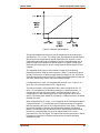
The L-Series actuator is ready for operation immediately (within 0.25 second)
when the power supply is connected. Power may be connected to the control at
the same time the engine starter motor is engaged.
On an engine shutdown command, the independent engine shutdown solenoid
or solenoid valve in the fuel supply should be de-activated and the power supply
disconnected from the speed control. This shutdown signal should be sent
directly from the engine control panel and should be independent and separate
from the L-Series control.
WARNING—EMERGENCY STOP
The L-Series control should not be used as the primary means of shutting
down the engine.
Starting the Engine
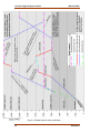
A typical engine starting sequence will look like this, if no shutdown faults are
detected:
When powered-up, the L-Series control will be in position control at the
configured min position. If a Run Enable discrete input is configured, it must be
closed. When the starter is engaged, the speed will increase above the Start
Speed 1 Threshold, and the control will position the shaft to the Start Fuel
position demand. If two Start Fuel positions are used and speed increases above
the Start Speed 2 Threshold, the control will position the shaft to the Start Fuel 2
position setting. Once the engine speed is above the Run Speed Threshold, the
control will switch from start fuel demand to the fuel demand from the speed
control PID. At this point, the unit is in speed control and will control the engine to
the speed setpoint. The PID position during starting is tracking the start fuel
values, providing a bumpless transfer to speed control. At this point, the speed
setpoint increases to the configured or selected setting—Idle, Rated, Rated 1, or
Rated 2.
If a shutdown fault is detected, the control will drive the output to the configured
fail direction position.
Control Features Description
As you review the following features, keep in mind that most applications will only
require a few of the functions to be activated. The choices are available to
provide maximum flexibility in a single package. The user must set up the
actuator direction, speed input, setpoint logic, and desired I/O. From the
dynamics functions area, the user can set as many or as few as is necessary for
stable operation. The user can choose all or none of the fuel limiter functions,
speed setpoint modifiers, alarm/shutdown functions, security and logic functions
depending on the application.
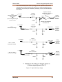
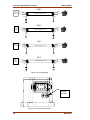
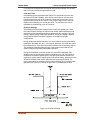
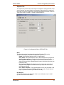
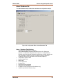
The control I/O consists of input power, a speed input, 4 configurable aux inputs,
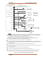
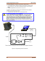
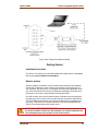
a status output, and an actual position indication (see Figure 4-1).
32
Woodward