1
CW12 GPS
User Manual
Issue: V 12
Bulletin
Revision
Date
NS04-UM
12
07 May 2010
Table of Contents
1. INTRODUCTION.................................................................................................................................................................4
2. SPECIFICATION..............................................................................................................................................................6-8
2.1 Performance................................................................................................................................................... 6
2.2 Block Diagram................................................................................................................................................ 6
2.3 CW12 GPS MTIE Performance...................................................................................................................... 6
2.4 Migrating from Motorola M12+ to NavSync CW12......................................................................................... 7
2.5 Auto survey (timing versions only).................................................................................................................. 7
2.6 T-RAIM Algorithm (timing versions only)......................................................................................................... 7
3. PHYSICAL CHARACTERISTICS....................................................................................................................................8-9
3.1 Electrical Connections.................................................................................................................................... 8
3.2 Interface Protocol............................................................................................................................................ 9
4. OPERATING MODES ........................................................................................................................................................9
5. POWER MANAGEMENT....................................................................................................................................................9
6. COMMUNICATION PROTOCOLS...............................................................................................................................10-60
6.1 Port Configuration......................................................................................................................................... 10
6.2 Output Format.........................................................................................................................................10-48
6.2.1 Motorola Binary Format....................................................................................................................... 10
6.2.1.1 One Pulse Per Second (1PPS) Timing............................................................................................. 11
6.2.1.2 1PPS Cable Delay Correction and 1PPS Offset............................................................................... 11
6.2.1.3 Supported Motorola Binary I/O commands.................................................................................12-48
6.2.1.3.1 Satellite Mask Angle Message (@@Ag)................................................................................... 13
6.2.1.3.2 Satellite Ignore List Message (@@Am).................................................................................... 14
6.2.1.3.3 Position Hold Parameters Message (@@As)........................................................................... 15
6.2.1.3.4 Time Correction Select (@@Aw).............................................................................................. 16
6.2.1.3.5 1PPS Time Offset Command (@@Ay)..................................................................................... 17
6.2.1.3.6 1PPS Cable Delay Correction Command (@@Az).................................................................. 18
6.2.1.3.7 Visible Satellite Data Message (@@Bb)................................................................................... 19
6.2.1.3.8 Almanac Status Message (@@Bd).......................................................................................... 20
6.2.1.3.9 Almanac Data Request (@@Be - response is Cb)................................................................... 21
6.2.1.3.10 Almanac Data Input (@@Cb response is @@Ch)................................................................. 22
6.2.1.3.11 Ephemeris Data Output Message (@@Bi response @@Bf )................................................ 23
6.2.1.3.12 Ephemeris Data Input (@@Bf response @@Cb).................................................................. 24
6.2.1.3.13 UTC Offset Output Message (@@Bo).................................................................................... 25
6.2.1.3.14 Request UTC/Ionospheric Data(@@Bp)................................................................................ 26
6.2.1.3.15 Reset to Defaults (@@Cf)...................................................................................................... 27
6.2.1.3.16 Receiver ID (@@Cj)............................................................................................................... 28
6.2.1.3.17 ASCII Position (@@Eq).......................................................................................................... 29
6.2.1.3.18 Combined Position Message (@@Ga)................................................................................... 31
6.2.1.3.19 Combined Time Message (@@Gb)........................................................................................ 32
6.2.1.3.20 1PPS Control Message (@@Gc)........................................................................................... 33
6.2.1.3.21 Position Control Message (@@Gd)........................................................................................ 34
6.2.1.3.22 T-RAIM Select Message (@@Ge).......................................................................................... 35
6.2.1.3.23 T-RAIM Alarm Message (@@Gf)............................................................................................ 36
6.2.1.3.24 Leap Second Pending Message (@@Gj)............................................................................... 37
6.2.1.3.25 Vehicle ID (@@Gk)................................................................................................................. 38
6.2.1.3.26 Channel Position/Status/Data (@@Ha).................................................................................. 39
6.2.1.3.27 Short Position Message (@@Hb)........................................................................................... 43
6.2.1.3.28 Channel Time RAIM Status Message (@@Hn)...................................................................... 45
6.2.1.3.29 12 Channel Self-Test Message (@@Ia)................................................................................. 47
6.2.1.3.30 System Power-On Failure (@@Sz)........................................................................................ 48
CW12 Software User Manual
Copyright ©2010 NavSync Ltd. All Rights Reserved
Page 2 of 68
Ver 12
Date: 05/07/10
Specifications subject to change without notice.
Table of Contents
6.2.2 NMEA Messages............................................................................................................................49-55
6.2.2.1 GLL, Geographic position, Lat/Lon............................................................................................... 49
6.2.2.2 GGA, GPS fix data....................................................................................................................... 50
6.2.2.3 GSA, GPS DOP and Active satellites........................................................................................... 50
6.2.2.4 GSV, GPS Satellites in View......................................................................................................... 51
6.2.2.5 RMC, Recommended Minimum data........................................................................................... 51
6.2.2.6 VTG, Course over ground and Ground speed.............................................................................. 52
6.2.2.7 POLYT, Time of Day..................................................................................................................... 52
6.2.2.8 POLYP, Position Data................................................................................................................... 53
6.2.2.9 POLYU, UTM Position Data.......................................................................................................... 54
6.2.2.10 POLYG, Local Grid Position Data............................................................................................... 54
6.2.2.11 POLYS, Satellite Status.............................................................................................................. 54
6.2.2.12 POLYI, Additional Information Message..................................................................................... 55
6.2.3 Proprietary Commands..................................................................................................................56-60
6.2.3.1 PRTH<Q|S|R>,DRLM: DEAD RECKONING LIMIT...................................................................... 56
6.2.3.2 PRTH<Q|S|R>,ILLH: INITIALIZED LAT, LONG, HEIGHT POSITION.......................................... 57
6.2.3.3 PRTH<Q|S|R>,ITIM: INITIALIZE TIME AND DATE...................................................................... 57
6.2.3.4 PRTH<Q|S|R>,MMSV: MIN & MAX SATELLITES FOR A POSITION SOLUTION..................... 58
6.2.3.5 PRTH<Q|S|R>,MCNO:MINIMUM SIGNAL CNO......................................................................... 58
6.2.3.6 PRTH<Q|S|R>,DYNA:
RECEIVER DYNAMICS..................................................................... 59
6.2.3.7 PRTH<Q|S|R>,RSET:
RE-SET THE RECEIVER................................................................... 59
6.2.3.8 PRTH<Q|S|R>,ELVM:
SATELLITE ELEVATION MASK......................................................... 60
6.2.3.9 PRTH<Q|S|R>,COMA: COMA MODE..................................................................................... 60
6.2.3.10 PRTH<Q|S|R>,FRQD: FREQUENCY OUTPUT SELECT...................................................... 60
7. Frequency Output............................................................................................................................................................61
8. Boot Options....................................................................................................................................................................62
8.1.1 Flash Programming............................................................................................................................. 62
9. NMEA Configurability Details....................................................................................................................................63-64
9.1 NMEA Configuration Query ($PRTHQ,U1OP):...................................................................................... 63
9.2 NMEA Configuration Set ($PRTHS,U1OP):........................................................................................... 64
9.3 UART Configuration Query ($PRTHQ,U1CM):....................................................................................... 64
9.4 UART Configuration Set ($PRTHQ,U1CM):........................................................................................... 64
10. MISCELLANEOUS....................................................................................................................................................65-67
10.1 Glossary............................................................................................................................................... 65
10.2 Contact Details.................................................................................................................................... 67
10.3 Internet Information.............................................................................................................................. 67
CW12 Software User Manual
Page 3 of 68
Copyright ©2010 NavSync Ltd. All Rights Reserved
Ver 12
Date: 05/07/10
Specifications subject to change without notice.
1. INTRODUCTION
The CW12 GPS receiver module is an integrated timing module powered by NavSync’s CW25 GPS receiver. It has been specifically designed for use in synchronization and timing applications,
The CW12 has an on-board programmable NCO oscillator that outputs a synthesized frequency up to 10 MHz that is steered
by the GPS receiver.
The CW12 has a self survey mode of operation that allows the receiver to enter a position hold mode to allow accurate timing
to be continued with only one satellite being tracked.
The output frequency is highly accurate and can achieve full PRC MTIE performance.
It can also track satellites and provide GPS synchronization in weak signal areas such as indoor applications. This reduces
the need for high antenna placement in many environments.
The CW12 receiver module is a 40 x 60 x 10 package with 10 pin (2 x 5) interface for ease of placement.
Key Features of the CW12 include:
•
•
•
•
•
•
•
•
•
•
•
3V - 3.6V operation
12 channel simultaneous operation
Fully calibrated to UTC at USNO
40 x 60 x 10 form factor
45 s typical cold start TTFF
38 s typical warm start TTFF
5 s typical hot start TTFF
<0.5 s reacquisition
Position hold for improved accuracy
Antenna current limit
Motorola M12 form factor
This document provides information on the Hardware and Software elements of the CW12.
Key information includes:
•
•
•
•
•
System Block Diagram
Maximum Ratings
Physical Characteristics
Signal Descriptions
Special Features
Operating Modes
Power Management
Communication Protocols
Description of Frequency Output
Boot Options
The CW12 receiver provides position, velocity, time and satellite tracking status information via a serial port. The CW12
receiver has a twelve parallel channel design capable of tracking twelve satellites simultaneously. The module receives the L1
GPS signal (1575.42 MHz) from the antenna and operates off the coarse/acquisition (C/A) code tracking. The code tracking is
carrier aided. The CW12 is designed specifically for precise timing applications.
CW12 Software User Manual
Copyright ©2010 NavSync Ltd. All Rights Reserved
Page 4 of 68
Ver 12
Date: 05/07/10
Specifications subject to change without notice.
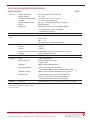
CW12-TIM GPS RECEIVER SPECIFICATIONS
SPECIFICATIONS
Physical
NOTE
Module dimensions
Supply voltages
Operating / Storage Temp
Humidity
Max Acceleration / Jerk
Datum
Connector
60mm (D) x 40mm (W) x 10mm (H)
3.0 - 3.6V
-40°C to +75°C / -55°C to +125°C
5% to 95% non-condensing
4g / 1gs-1 (sustained for less than 5 seconds)
WGS-84 Default
Data/Power: 10 pin (2 x 5) unshrouded header
on 0.050 inches centers. RF: MMCX
(subminiature snap-on)
Sensitivity
Acquisition/Tracking
-173dBW / -186dBW (-143dBm / -156dBm)
Acquisition
Time
Stand Alone (Outdoor)
Cold: <45s
Warm: <38s
Hot: <5s
Re-acquisition: <0.5s (90% confidence)
Accuracy Position: Outdoor / Indoor
Velocity
Latency
Raw Measurement Accuracy
Tracking
<5m rms / <50m rms
<0.05ms
<200ms
Pseudorange <0.3m rms, Carrier phase <5mm rms
Code and carrier coherent
Power
1 fix per second
0.6W typically
Serial
Multi-function I/O
Protocols
1pps Timing Output
Frequency Output
Receiver Type
1 port, CMOS levels
1PPS and Frequency Output
2 Status LEDs
NMEA 0183 or Motorola Binary
10ns rms accuracy, <5ns resolution
Pulse Width NMEA: 100 µS; Motorola Binary: 200ms
NMEA: 10 Hz to 10 MHz; Motorola Binary: 10 MHz
12 parallel channel x 32 taps up to 32 point FFT.
Channels, taps and FFT can be switched off to minimize power or simulate simpler designs.
Processor
ARM 966E-S on a 0.18 micron process at up to 120 MHz.
Interfaces
General
Note:
1. Timing Applications typically assume static operation.
2. Could be customized
CW12 Software User Manual
Page 5 of 68
Copyright ©2010 NavSync Ltd. All Rights Reserved
Ver 12
Date: 05/07/10
Specifications subject to change without notice.
1
2
2
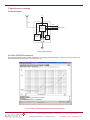
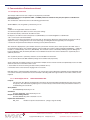
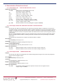
2. Specifications continued
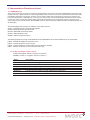
2.2Block Diagram
3V
L1 IN
1PPS
CW25
GPS
ENGINE
Power-On
Reset
FREQ OUT
NMEA / MOTOROLA BINARY
Ant
Supply
50mA
Current
Limit
Brownout
Supervisor
Battery
GND
Figure 1 Block Diagram
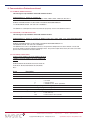
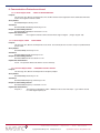
2.3CW12 GPS MTIE Performance
The graph below demonstrates the MTIE performance of the CW25-TIM output frequency relative to a Caesium atomic clock,
with the CW12 GPS operating with a clear view of the sky.
Figure 2 CW12’s 10 MHz Output MTIE Performance (PRC mask)
CW12 Software User Manual
Copyright ©2010 NavSync Ltd. All Rights Reserved
Page 6 of 68
Ver 12
Date: 05/07/10
Specifications subject to change without notice.
2. Specifications continued
2.4Migrating from Motorola M12+ to NavSync CW12
The CW12 was designed to meet the form and functionality of the M12 as closely as possible using NavSync’s CW25 receiver
module. The information in the table below identifies key similarities between the two products as well as advantages offered by
the CW12. This document will also offer guidelines on how to replace the M12 with the CW12, as well as how to design in the
CW12 to a new application.
Feature
M12
CW12
12 Channels High Sensitivity
1PPS
Variable Freq Output
Antenna Current Limiting
Voltage
Position accuracy (3D)
On-board battery
TRAIM
RTCM
Data Output Format
Yes
No
Yes (500ns) No
Yes
3V
25m
Yes (option) Yes
Yes
NMEA 0183 (4800) or Motorola Binary (9600)
Yes
Yes
Yes (10ns)
Yes (NMEA 0183)
Yes
3.0V - 3.6V
10m
Yes
Yes
Yes
NMEA 0183 Variable Baud Rate or
Motorola Binary (9600)
2.5Auto Survey (timing versions only)
The Automatic Site Survey mode simplifies system design for static timing applications. This automatic position determination
algorithm is user initiated and can be deactivated at any time.
The Automatic Site Survey averages a total of 10 minutes worth of valid 2D and 3D position fixes. If the averaging process is
interrupted, the averaging resumes where it left off when tracking resumes. Once the position is surveyed, the CW12 automatically enters the Position-Hold Mode.
Once the survey is completed, the Time RAIM algorithm is capable of error detection, isolation, and removal. The status of
the Automatic Site Survey and Position-Hold Mode is retained in RAM when the receiver is powered down only if battery backup
power is provided.
2.6T-RAIM Algorithm (timing versions only)
Time Receiver Autonomous Integrity Monitoring (RAIM) is an algorithm in the CW12 timing GPS receivers that uses redundant
satellite measurements to confirm the integrity of the timing solution.
The basic idea is that in most surveying systems and instruments, there are more measurements taken than are required to
compute the solution. The excess measurements are redundant. Hence a system can use redundant measurements in an averaging scheme to compute a solution that is more robust and accurate than using only the minimum number of measurements
required. Once a solution is computed, the measurements can be inspected for errors. This represents the essence of Time
RAIM. In order to perform precise timing, the GPS receiver position is determined and then the receiver is put into position-hold
mode where the receiver no longer solves for position. With the position known, the time is the only remaining unknown. In order to compute the time, the GPS receiver only requires one satellite. If multiple satellites are tracked, then the time solution is
based on an average of the satellite measurements.
When the average solution is computed, it is compared to each individual satellite measurement to screen for errors. A residual is computed for each satellite by differencing the solution average and the measurement. If there is a bad measurement in
the set, then the average will be skewed and one of the measurements will have a large residual. If the magnitude of the residuals exceeds the expected limit, then an alarm condition exists and the individual residuals are checked. The magnitude of each
residual is compared with the size of the expected measurement error. If the residual does not fall within a defined confidence
level of the measurement accuracy, then it is flagged as an error. Once an error is identified, then it is removed from the solution
and the solution is recomputed and checked again for integrity.
When the T-RAIM algorithm is enabled (using the @@Ge Motorola Binary command), the CW12 bases the reported T-RAIM
Status and Solution (@@Hn Motorola Binary message), from the number of satellites tracked and the 1-sigma timing accuracy
estimate (TACC). The CW12 is capable of removing faulty satellites from the solution if the number of satellites in the solution is
5 or more. The receiver can continue to detect faulty satellites while number of visible satellites is 3 or more. Finally if number of
visible satellites is 2 or fewer neither would be possible due to scarce information available.
CW12 Software User Manual
Page 7 of 68
Copyright ©2010 NavSync Ltd. All Rights Reserved
Ver 12
Date: 05/07/10
Specifications subject to change without notice.
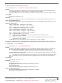
3. PHYSICAL CHARACTERISTICS
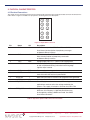
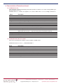
3.1Electrical Connections
The CW12 receives electrical power and receives/transmits I/O signals through a 10-pin power/data connector mounted on the
CW12. Refer to Figure 2 and Table 2 for pin position, numbering and a short description.
1 ¡
2
¡
3 ¡
4
¡
5 ¡
6
¡
7 ¡
8
¡
9 ¡
10
¡
Figure 3 10-pin CW12 Connector
Pin
Name
I/O
Description
1
TXD
O
NMEA 0183 output from GPS Core. Refer to CW25 User Manual for description of proprietary messages
or Motorola Binary interface.
2
RXD
I
NMEA 0183 input to GPS Core. Refer to CW25 User Manual for description of proprietary commands
or Motorola Binary interface.
3
VCC
PWR
4
1PPS
O
5
GND
PWR
Power supply return to ground.
6
VBATT
PWR
~3V needs to be supplied here to keep the real time
clock alive while the receiver is powered off.
7
BOOTSEL
I
Boot select pin allows Firmware to be upgraded when grounded.
8
RTCM
I
Not supported in this version.
9
ANT_SUPPLY
PWR
FREQ_OUT
O
10
Voltage Supply input. 3.0 - 3.6VDC to be supplied here.
1 Pulse Per Second output. Pulse is 100uS (NMEA 0183) or 200 mS (Motorola Binary) in duration and rising edge
signifies top of second.
Power supply for active antenna used. The voltage applied here needs to reflect the voltage needed by the antenna. This supply is limited to ~50mA on the CW12-TIM.
Programmable synchronized frequency output from GPS core, this frequency is 10MHz by default but may be changed by sending a NMEA command. See CW25 User Manual for details.
Table 2: Signal Description of IO Connector on the CW12
CW12 Software User Manual
Copyright ©2010 NavSync Ltd. All Rights Reserved
Page 8 of 68
Ver 12
Date: 05/07/10
Specifications subject to change without notice.
3. Physical Characteristics continued
3.2Interface Protocol
The CW12 receiver has one TTL serial data port. This port is configured as data communications equipment (DCE) port and
provides the main control and data path between the CW12 receiver and the system controller.
The I/O port operates under interrupt control. Incoming data is stored in a buffer that is serviced by the CW12 receiver’s operating program. This buffer is serviced every 16ms. The CW12 receiver supports either Motorola Binary or NMEA 0138 output
data format.
Format
Motorola Binary
NMEA 0138
Type
Direction
Port
Baud Rate
Parity
Data bits
Start/Stop
Binary
In/Out
1
9600
None
8
1/1
ASCII
In/Out
1
38400
None
8
1/1
Table 3 CW12 Interface Protocol
4. OPERATING MODES
For stand alone operation the receiver will perform cold starts with no prior knowledge of position or GPS satellite data such as
almanacs and ephemeris provided the antenna has a clear view of the sky to provide signal strengths of 35dB or higher. The
receiver should be allowed to track satellites for a minimum period of 15 minutes to ensure all almanac information has been
received. The GPS data is stored in the EEPROM memory fitted to the CW25. Once the receiver has been initialized and has
current almanac and ephemeris data it may then be taken indoors for test with low level signals.
Hot starts (current ephemeris data held in EEPROM) can be performed with low level signals (indoors).
5. POWER SUPPLY AND MANAGEMENT
The power supply requirements of the CW12 can all be provided from a single 3.6V supply. To simplify system integration onboard regulators provide the correct voltage levels for the RF and oscillator (2.9V or 3.0V) and low voltage digital core (1.8V). If
the source impedance of the power supply to the CW12 is high due to long tracks, filtering or other causes, local decoupling of
the supply signals may be necessary. Care should be taken to ensure that the maximum supply ripple at the pins of the CW12 is
50mV peak to peak.
The CW12 GPS receiver is a low power module consuming less than 250mW for a 1Hz update of position. The receiver
contains software to dynamically reduce power consumption wherever possible. Where channels and taps are not needed they
are switched off. When the processor is not required it is put into a halt until interrupt state and the chips clock system is geared
down to reduce power consumption. All of these things are performed automatically without any user configuration. If further
power saving is required the receiver can be reprogrammed with smaller GPS configurations thereby permanently switching off
portions of the GPS hardware and allowing the processor speed to be reduced, thereby saving power.
For battery powered applications which need to reduce the power consumption it is possible to switch the receiver into Coma
Mode. This configures the RF front end into sleep mode, switches off internal peripherals and places the processor in a sleep
state waiting for an interrupt. Power consumption is typically reduced to <30mW.
Coma Mode is initiated through the COMA serial command, details of which can be found in section 6.2.3.9.
6. COMMUNICATIONS PROTOCOLS
Full descriptions of the communications protocols used by the CW12 can be found in section 6.2.1 (Motorola Binary) and 6.2.2
(NMEA).
CW12 Software User Manual
Page 9 of 68
Copyright ©2010 NavSync Ltd. All Rights Reserved
Ver 12
Date: 05/07/10
Specifications subject to change without notice.
6.1 Port Configuration
There is only one serial port available on the CW12. This port will support either Motorola Binary or NMEA 0138 data flow formats but not both. The chosen protocol is hard coded into the CW12 firmware and cannot be changed only if a different firmware is flashed.
Port
TX Pin
RX Pin
Baud Rate
Function
1
1
1 (default)
1 (special build)
2 (default)
2 (special build)
9600
38400
Motorola Binary Format
NMEA
All ports are configured as 8, bits no Parity, with no handshaking.
6.2 Output Format
There are two types of messages that can be output from the CW12 receiver, these are split into Motorola Binary messages and
NMEA sentences. Only NMEA output represents ASCII strings.
6.2.1 Motorola Binary Format
The binary data messages used by the GPS receiver consist of a variable number of binary characters. These binary
messages begin with the ASCII @@ characters and are terminated with the ASCII carriage return and line feed <CR><LF>.
The first two bytes after the @@ characters are two ASCII characters that identify the particular structure and format of
the remaining binary data. The byte preceding the termination <CR><LF> of all messages is a single byte checksum (the
exclusive-or of all message bytes after the @@ and before the checksum).
Every message has the following components:
• Message Start:
@@ (two hex 40s) denotes start of binary message.
• Message ID:
(A..Z)(a..z, A..Z) ASCII upper-case letter, followed by an ASCII lower-case or upper case letter. These two characters together identify
the message type and imply the correct message length and format.
• Binary Data Sequence:
Variable number of bytes of binary data dependent on the command type.
• Checksum:
C The exclusive-or of all bytes after the @@ and prior to the checksum.
• Message Terminator:
<CR><LF> carriage return and line feed denoting the end of the binary message.
Every GPS receiver input command has a corresponding response message so that the user can determine whether
the input commands have been accepted or rejected by the GPS receiver.
The user must take care to correctly format the input command. Pay particular attention to the number of parameters
and their valid ranges. An invalid message could be interpreted as a valid unintended message. A beginning @@, a valid
checksum, a terminating carriage return line feed, the correct message length and valid parameter ranges are the only
indicators of a valid input command to the GPS receiver. For multi-parameter input commands, the GPS receiver will
reject the entire command if one of the input parameters is out of range.
Input and output data fields contain binary data that can be interpreted as scaled floating point or integer data.
The field width and appropriate scale factors for each parameter are described in the individual I/O message format
descriptions. Polarity of the data (positive or negative) is described via the two’s complement presentation.
Input command messages can be stacked into the GPS receiver input buffer, up to the depth of the message
buffer. The GPS receiver will operate on all full messages received and will process them in the order they are received.
Previously scheduled messages may be output before the responses to the new input commands.
Every input command has a corresponding output response message. This enables the user to verify that the GPS
receiver accepted the input command. The GPS receiver response to properly formatted commands with at least one outof-range parameter is to return the previous unchanged value(s) of the parameter(s) in the response message.
For the case where more than one output message is scheduled during the same one second interval, the GPS
receiver will output all scheduled messages but will attempt to limit the total number of bytes transmitted each second to
750 bytes.
For the purpose of testing the CW12’s Motorola Binary commands and messages we have used the Motorola’s
WinOnCore v1.2. For more information on the above mentioned software please consult the application’s user manual or
help files.
CW12 Software User Manual
Copyright ©2010 NavSync Ltd. All Rights Reserved
Page 10 of 68
Ver 12
Date: 05/07/10
Specifications subject to change without notice.
6. Communications Protocols continued
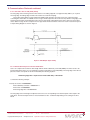
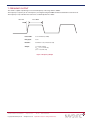
6.2.1.1 One Pulse Per Second (1PPS) Timing
The rising edge of the 1PPS signal is the time reference. The falling edge will occur approximately 200 ms (±1 ms) after
the rising edge. The falling edge should not be used for accurate time keeping.
The position/status/data message and the time RAIM setup and status message are the only output messages
containing time information. If enabled, these messages will be output from the receiver shortly after the rising edge of the
1PPS signal. Generally, the first data byte in the first message will be output between 0 to 50 ms after. For the position/
status/ data message, the time output in the message reflects the best estimate of the most recent measurement epoch.
A simple timing diagram is shown in Figure 4.
Figure 4 IPPS Output Signal Timing
6.2.1.2 1PPS Cable Delay Correction and 1PPS Offset
Users can compensate for antenna cable length with the 1PPS Cable Delay Command (@@Az). The 1PPS can also be
positioned anywhere in the one second window using the 1PPS Offset command (@@Ay). The rising edge of the 1PPS is
placed so that it corresponds to the time indicated by the following equation:
1PPS rising edge time = top of second -1PPS cable delay + 1PPS offset
Consider the following example:
True Top of second = 10.000000000 s
1PPS cable delay correction = 0.000654321 s
1PPS offset = 0.100000000 s
1PPS rising edge time = 10.099345679 s
The rising edge of the 1PPS signal is adjusted so that it occurs corresponding to the fractional part of time equal to the
total above. The fractional part of time is measured relative to UTC or GPS time depending on the setting of the Time
Mode.
CW12 Software User Manual
Page 11 of 68
Copyright ©2010 NavSync Ltd. All Rights Reserved
Ver 12
Date: 05/07/10
Specifications subject to change without notice.
6. Communications Protocols continued
6.2.1.3 Supported Motorola Binary I/O commands
Command
@@Ag
@@Am
@@As
@@Aw
@@Ay
@@Az
@@Bb
@@Bd
@@Be
@@Bf
@@Bi
@@Bo
@@Bp
@@Cb
@@Cc
@@Cf
@@Ch
@@Cj
@@Eq
@@Ga
@@Gb
@@Gc
@@Gd
@@Ge
@@Gf
@@Gj
@@Gk
@@Ha
@@Hb
@@Hn
@@Ia
@@Sz
Name
Satellite Mask Angle
0
Satellite Ignore List
none
Position-Hold Position
0,0,0
UTC Time Correction
Enabled
1PPS Offset
n/a
1PPS Cable Delay
n/a
Visible Satellites
Output off
Almanac Status
Almanac Data Output Output off
Ephemeris Data Input
Output off
Ephemeris Data Output
Output off
UTC Offset Status
Output off
Request UTC/Ionospheric Data
Output off
Almanac Data Input
n/a
Ephemeris Data Response
n/a
Set to defaults
n/a
Almanac Data Response
n/a
Receiver ID
n/a
ASCII Position
n/a
Combined Position
0,0,0
Combined Time
12:00:00,1/1/98, 0:0
1PPS Control
1PPS always on
Position Control
No hold
T-RAIM Select Message
Disabled
T-RAIM Alarm Message
1000ns
Leap Second Status
n/a
ID Tag Message
n/a
Position/Status/Data
Message off
Short Position Message
Message off
12 Channel T-RAIM Status Message
Message off
Self-Test
n/a
System Power-On Failure
n/a
Default
Comments
GPS only
Polled only
No support for pages 4/25 and 5/25 – Polled only Response is @@Cb
Response is @@Cc
Polled only
Polled only
Polled only
Output - response to Be or Input - response is Ch
Response to @@Bf
Response to @@Cb
Provides information on Software Load; No unique serial or manufacture data
No differential support
GPS only
Not initialized to serial Not used in commands
ID Tag not used No antenna status
ID Tag not used No antenna status
Very limited support: Only FLASH and ROM tested
No support for antenna status Does not check
RTC/Temperature/Correlator
Table 4 GPS Receiver Supported Binary Messages
CW12 Software User Manual
Copyright ©2010 NavSync Ltd. All Rights Reserved
Page 12 of 68
Ver 12
Date: 05/07/10
Specifications subject to change without notice.
6. Communications Protocols continued
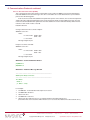
6.2.1.3.1 Satellite Mask Angle Message (@@Ag)
The GPS receiver will attempt to track satellites for which the elevation angle is greater than the satellite mask
angle. This parameter allows the user to control the elevation angle that is used for this decision.
Range : 0 to 89 degrees
Default : 0 degrees
Query current Satellite Mask Angle:
@@AgxC<CR><LF>
where: x = 1 ‘0xFF’ hex byte
0xD9= checksum
Message length: 8 bytes
Change current Satellite Mask Angle:
@@AgdC<CR><LF>
where: d = degrees 0..89 degrees (0x00 – 0x59)
C = checksum
Message length: 8 bytes
Response to either command:
@@AgdC<CR><LF>
where: d = degrees 0..89 degrees (0x00 – 0x59)
C = checksum
Message length: 8 bytes
WinOnCore – Command Monitor Window
(Tx)@@Ag 20
(Rx)@@Ag 20
WinOnCore – Additional Message Window
———————————————————————————
@@Ag (Satellite Mask Angle) command...
———————————————————————————
Satellite Mask Angle
Mask Angle: 32 degrees
CW12 Software User Manual
Page 13 of 68
Copyright ©2010 NavSync Ltd. All Rights Reserved
Ver 12
Date: 05/07/10
Specifications subject to change without notice.
6. Communications Protocols continued
6.2.1.3.2 Satellite Ignore List Message (@@Am)
It is useful to have the flexibility to delete particular satellite identification numbers from the selection process. The
GPS receiver includes, in its list of satellites to track, all satellites that are healthy and in the almanac. The user can
select to ignore particular satellites in the almanac by issuing an Ignore Satellite Command. In addition, the user
can restore any previously ignored satellite IDs by issuing an Include Satellite Command. The user may notice a
delay between issuing this command and the actual removal or inclusion of particular satellites.
Default value: All satellite SVIDs included.
Query current SV Ignore List:
@@AmxxxxxC<CR><LF>
where: xxxxx = 5 bytes, all 0x00
0x2C = checksum
Message length: 12 bytes
Change current SV Ignore List:
@@AmkssssC<CR><LF>
where: k = 0x00 - fixed hex constant
ssss = 32 bit binary field, each bit representing one SVID. (msb = SVID 32, lsb = SVID 1)
1 = Ignore
0 = Include
C = checksum
Message length: 12 bytes
Response Message to either command:
@@AmkssssC<CR><LF>
where: k = 0x00 fixed hex constant
ssss = 32 bit binary field, each bit representing one SVID. (msb = SVID 32, lsb = SVID 1)
1 = Ignore
0 = Include
C = checksum
Message length: 12 bytes
WinOnCore – Command Monitor Window
(Tx)@@Am 0023E9163A
(Rx)@@Am 0023E9163A
will add the following satellites to the ignore list:
SV: 30;26;25;24;23;22;20;17;13;11;10;6;5;4;2
WinOnCore – Additional Message Window
———————————————————————————
@@Am (Satellite Ignore List) command...
———————————————————————————
Satellite Ignore List
Satellite Ignore List: 23E9163Ah
CW12 Software User Manual
Copyright ©2010 NavSync Ltd. All Rights Reserved
Page 14 of 68
Ver 12
Date: 05/07/10
Specifications subject to change without notice.
6. Communications Protocols continued
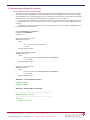
6.2.1.3.3 Position Hold Parameters Message (@@As)
The user can specify Position Hold coordinates both for timing applications to increase the timing accuracy. This
command is used to enter the position to be held.
The position is specified in the same units and referenced to the same datum as the initial position
coordinates of latitude, longitude and height. The height parameter is referenced to the GPS reference ellipsoid.
Note that all three parameters must be specified. The valid ranges of each parameter are the same as those
specified in the Combined Position Message (@@Ga).
This command will only be executed if Position Hold is disabled. Position Hold is controlled using the @@Gd
message.
Default values:
Latitude = 0° (Equator)
Longitude = 0° (Greenwich Meridian)
Height = 0 m (GPS Height)
Query current Position Hold Parameters:
@@AsxxxxxxxxxxxxxC<CR><LF>
where:
xxxxxxxxxxxxx = 13 out of range hex bytes: 0xFF
C = 0xCD
Message length: 20 bytes
Change current Position Hold Parameters:
@@AslllloooohhhhtC<CR><LF>
where:
llll = latitude in mas -324,000,000..324,000,000 (-90º..90º)
oooo = longitude in mas -648,000,000..648,000,000 (-180º..180º)
hhhh = height in cm -100000..1,800,000 (-1,000.00..18,000.00 m)
t = height type 0 = GPS height
C = checksum
Message length: 20 bytes
Response to either command:
@@AslllloooohhhhtC<CR><LF>
where:
llll = latitude in mas -324,000,000..324,000,000 (-90º..90º)
oooo = longitude in mas -648,000,000..648,000,000 (-180º..180º)
hhhh = height in cm -100000..1,800,000 (-1,000.00..18,000.00 m)
t = height type 0 = GPS height
C = checksum
Message length: 20 bytes
WinOnCore – Command Monitor Window
First of all we disable Hold Position and then we input the position hold parameters.
(TX)@@Gd 00
(RX)@@Gd 00
(Tx) @@As 0B1D41730023F87A0000880600
(Rx) @@As 0B1D41730023F87A0000880600
WinOnCore – Additional Message Window
———————————————————————————
@@As (Hold Position Parameters) command...
———————————————————————————
Hold Position Parameters
Latitude: 51.796284 degrees
Longitude: 0.654825 degrees
Height:
348.220000 m Type: 0 (0 - GPS, 1 - MSL)
CW12 Software User Manual
Page 15 of 68
Copyright ©2010 NavSync Ltd. All Rights Reserved
Ver 12
Date: 05/07/10
Specifications subject to change without notice.
6. Communications Protocols continued
6.2.1.3.4 Time Correction Select (@@Aw)
This command selects the time reference (either GPS or UTC) used in the @@Ha 12 Channel Position/Status/
Data and @@Hb Short Position Messages. This Time command is also used to determine the synchronization
point for the 1PPS timing pulse.
If the receiver has not downloaded the UTC parameters portion of the almanac, the receiver will output time
equal to GPS time and a flag denoting the lack of UTC parameters will be set in the @@Ha message. Once the
receiver has downloaded the UTC parameters from the satellites the receiver will automatically switch the time
reference to UTC if UTC mode is selected.
Default mode: UTC
Change current UTC Time Correction Option:
@@AwmC<CR><LF>
where:
m = time mode: 0x00 = GPS
0x01 = UTC
C = checksum
Message length: 8 bytes
Response to either command:
@@AwmC<CR><LF>
where:
m = time mode: 0x00 = GPS
0x01 = UTC
C = checksum
Message length: 8 bytes
WinOnCore – Command Monitor Window
(TX)@@Aw 00
(RX)@@Aw 00
WinOnCore – Additional Message Window
———————————————————————————
@@Aw (Time Mode) command...
———————————————————————————
Time Mode
Mode: 0
(0 - GPS, 1 - UTC)
For example:
1. Set @@Ha01 - Position/Status Data output each second.
2. Set @@Aw 00 – GPS time
3. Observe the time
4. Set @@Aw 01 – UTC time
5. Observe the time and notice the 14 second offset between the GPS and UTC time. (Note: When this user manual was written there was a 14 seconds offset between the GPS and UTC time.)
CW12 Software User Manual
Copyright ©2010 NavSync Ltd. All Rights Reserved
Page 16 of 68
Ver 12
Date: 05/07/10
Specifications subject to change without notice.
6. Communications Protocols continued
6.2.1.3.5 1PPS Time Offset Command (@@Ay)
The CW12 outputs a one pulse-per second (1PPS) signal with the rising edge placed on top of the UTC or GPS
one second tic mark, depending on which time reference has been selected by the user. The 1PPS Time Offset
command allows the user of CW12 timing receivers to offset the 1PPS time mark in one nanosecond increments.
This offset can be used to place the 1PPS signal anywhere within the one second epoch.
The resolution of this parameter is one nanosecond. This does not imply that the 1PPS output by the CW12
is accurate to this level. This command only allows the user to change the location of the average placement of
the pulse.
The absolute accuracy of the signal is a function of GPS time accuracy, and is subject to degradation due to
U.S. Department of Defense policy.
Range: 0.000000000 to 0.999999999 s Default value: 0.000000000 s Resolution: 1 ns
Query current 1PPS Time Offset: @@AyxxxxC<CR><LF>
where:
xxxx = 4 out of range hex bytes: 0xFF
C = 0x38
Message length: 11 bytes
Change current 1PPS Time Offset: @@AyttttC<CR><LF>
where:
tttt = time offset in ns 0..999,999,999 (0.0 to 0.999999999 s)
C = checksum
Message length: 11 bytes
Response to either command: @@AyttttC<CR><LF>
where:
tttt = time offset in ns 0..999,999,999 (0.0 to 0.999999999 s)
C = checksum
Message length: 11 bytes
WinOnCore – Command Monitor Window
(Tx)@@Ay 004C4B40
(Rx)@@Ay 004C4B40
WinOnCore – Additional Message Window
———————————————————————————
@@Ay (1PPS Offset) command...
———————————————————————————
1PPS Offset
Time Offset: 5000000 ns
CW12 Software User Manual
Page 17 of 68
Copyright ©2010 NavSync Ltd. All Rights Reserved
Ver 12
Date: 05/07/10
Specifications subject to change without notice.
6. Communications Protocols continued
6.2.1.3.6 1PPS Cable Delay Correction Command (@@Az)
The CW12 timing receiver outputs a 1PPS signal, the rising edge of which is placed at the top of the GPS
or UTC one second time mark epoch as specified by the Time Mode command. The 1PPS Cable Delay
Correction command allows the user to offset the 1PPS time mark in one nanosecond increments relative to the
measurement epoch.
This parameter instructs the GPS receiver to output the 1PPS output pulse earlier in time to compensate for
antenna cable delay. Up to one millisecond of equivalent cable delay can be removed. Zero cable delay is set
for a zero-length antenna cable. The user should consult a cable data book for the delay per unit length for the
particular antenna cable used in order to compute the total cable delay needed for a particular installation.
This parameter may also be employed by the user to adjust the position of the 1PPS to compensate for
other system delays.
Range: 0.000 to 0.000999999 s
Default value: 0.000 s
Resolution: 1 ns
Query current 1PPS Cable Delay Correction: @@AzxxxxC<CR><LF>
where:
xxxx = 4 out of range hex bytes: 0xFF
Checksum = 0x3B
Message length: 11 bytes
Change current 1PPS Cable Delay Correction: @@AzttttC<CR><LF>
where:
tttt = time offset in ns 0..999,999 ns (0.0 to 0.000999999 s)
C = checksum
Message length: 11 bytes
Response to either command: @@AzttttC<CR><LF>
where:
tttt = time offset in ns 0..999,999 ns (0.0 to 0.000999999 s)
C = checksum
Message length: 11 bytes
WinOnCore – Command Monitor Window
(Tx)@@Az 0000C350
(Rx)@@Az 0000C350
WinOnCore – Additional Message Window
———————————————————————————
@@Az (1PPS Cable Delay) command...
———————————————————————————
1PPS Cable Delay
Time Offset: 50000 ns
CW12 Software User Manual
Copyright ©2010 NavSync Ltd. All Rights Reserved
Page 18 of 68
Ver 12
Date: 05/07/10
Specifications subject to change without notice.
6. Communications Protocols continued
6.2.1.3.7 Visible Satellite Data Message (@@Bb)
This command requests the results of the most current satellite visibility computation. The response message
gives a summary of the satellite visibility status showing the number of visible satellites, the Doppler frequency
and the location of the currently visible satellites. The reference position for the most recent satellite alert is the
current position coordinates.
Note that these coordinates may not compare to the GPS receiver’s actual position when initially turned on,
since the GPS receiver may have moved a great distance since it was last used.
Default mode: Polled
Query Current Visible Satellite Data:
@@BbmC<CR><LF>
where:
m = mode 0x00 = output response message once (polled) 0x01 = output response message data
when visibility data changes (approximately once every 5-7 seconds) – (The above description is not supported by the CW12 GPS receiver. The CW12 supports only the polled mode or continuous
mode. However the description has been kept in order to preserve the consistency with the
Motorola M12 user manual.)
C = checksum
Message length: 8 bytes
Response to above command:
@@Bbn iddeaas iddeaas iddeas iddeaas iddeaas iddeaas iddeaas iddeaas iddeaas iddeaas iddeaas iddeaas
C<CR><LF>
where:
n = number of visible sats 0 ..12
For each visible satellite, up to n fields contain the following valid data
i - satellite ID 1 .. 32
dd - Doppler in Hz -5000..5000
e - elevation in degrees 0..90
aa - azimuth in degrees 0..359
s - satellite health 0 = healthy and not removed
1 = unhealthy and removed
C = checksum
Message length: 92 bytes
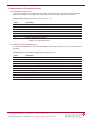
WinOnCore – Command Monitor Window
(Tx)@@Bb 00
(Rx)@@Bb
0FFD70080042000E16D80A0069000804530D0121001C168B14013E000301102F008100000000000000001B01
E104010A001606062B0043000B15AC2800FD0000000000000000130A9E57009A0012FF500E002700
WinOnCore – Additional Message Window
———————————————————————————
@@Bb (Visible Satellite Status) command...
———————————————————————————
Visible Satellite Status
Visible Satellites: 10
Satellite details found in Azimuth & Elevation Window
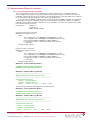
Figure 5 WinOncore’s Azimuth and Elevation Window
CW12 Software User Manual
Page 19 of 68
Copyright ©2010 NavSync Ltd. All Rights Reserved
Ver 12
Date: 05/07/10
Specifications subject to change without notice.
6. Communications Protocols continued
6.2.1.3.8 Almanac Status Message (@@Bd)
This command requests almanac status information corresponding to the satellite almanac data currently stored
in RAM. The GPS receiver continually captures a complete new almanac to internal RAM while tracking satellites.
If an existing almanac is stored in RAM on power-up, satellite visibility information will be available immediately.
If no almanac data is stored in RAM on power-up, the receiver will download a new almanac and then compute
satellite visibility information.
Query Current Almanac Status:
@@BdmC<CR><LF>
where:
m = mode 0x00 = Output status once (polled)
0x01 = Output status when RAM almanac data changes. (The above functionality is no supported by the CW12 GPS receiver. The CW12 supports only the polled mode or continuous mode. However the description has been kept in order to preserve the
consistency with the Motorola M12 user manual.)
C = checksum
Message length: 8 bytes
Response to above command:
@@BdvwtassssrrrrrrrrC<CR><LF>
where:
v = almanac valid flag
0x00 = no almanac in receiver
0x01 = valid almanac in receiver
w = almanac week number (raw) 0x00..0xFF (ICD-GPS-200)
t = time of almanac (raw) 0x00..147 (ICD-GPS-200)
a = number of available SVs 0x00..0x20
ssss = SVs in almanac 32 bit (2 byte) binary field, each bit represents one SVID (msb = SVID 32; 1sb = SVID 1)
rrrrrrrr = 8 reserved bytes
C = checksum
Message length: 23 bytes
WinOnCore – Command Monitor Window
(Tx)@@Bd 00
(Rx)@@Bd 015A471D7FFFEFFE0000000000000000
WinOnCore – Additional Message Window
———————————————————————————
@@Bd (Almanac Status Message) command...
———————————————————————————
Almanac Status Message
Almanac Valid Flag: 1 (0 - No Almanac, 1 - Valid Almanac)
Almanac Week: 90
Time of Almanac: 71
SVs in Almanac: 1D7FFFEFh
CW12 Software User Manual
Copyright ©2010 NavSync Ltd. All Rights Reserved
Page 20 of 68
Ver 12
Date: 05/07/10
Specifications subject to change without notice.
6. Communications Protocols continued
6.2.1.3.9 Almanac Data Request (@@Be - response is Cb)
This command is used to command the CW12 to output its current almanac data. The user has the option of
requesting the almanac data output one time (polled), or each time the almanac data changes. (The above
functionality is no supported by the CW12 GPS receiver. The CW12 supports only the polled mode or continuous
mode. However the description has been kept in order to preserve the consistency with the Motorola M12 user
manual.)
Almanac data for the GPS satellites is transmitted in words 3 through 10 of subframe 5 (pages 1 through 25),
and words 3 through 10 of subframe 4 (pages 2 through 5, 7 through 10, and 25) of the satellite broadcast data
message. Refer to the ICD-GPS-200 for a detailed almanac data description.
The CW12 outputs the almanac data through a series of output messages, each of which is identified by
the particular subframe and page numbers. The data fields of each individual message correspond to words 3
through 10 of the broadcast data. Each word contains 24 data bits.
The entire almanac data output consists of 34 output response messages corresponding to the 25 pages of
subframe 5 and the 9 pages in subframe 4 that contain almanac data (pages 2 through 5, 7 through 10, and 25).
The total message output for one output request is 1122 bytes including the @@Cb prefix and the checksum,
carriage return, and line feed for each output. The output message begins with subframe 5 page 1.
The CW12 will output about 750 bytes of message data for each one-second-output opportunity. If
selected, the almanac response message is output until the total number of bytes sent in a one second epoch
exceeds 750. The remainder of the almanac message is sent in the next one second epoch (up to the 750 byte
limit per second) until the entire almanac data is output.
If the user issues this command and the receiver does not contain an almanac, the receiver returns one
response message with the subframe and page bytes equal to zero.
Some of the above functionality is not supported by the CW12 GPS receiver, namely our solution doesn’t
output subframe 4 page 25 and subframe 5 page 25. For more references regarding the information contained in
those pages please consult “Interface Specification, ICD-GPS-200, Revision D, IRN-200D-001, 7 March 2006”.
Also CW12 supports only the polled mode. However the previous description has been kept in order to preserve
the consistency with the Motorola M12 user manual.
Default mode: Polled
WinOnCore – Command Monitor Window
(Tx)@@Be 01
(Rx)@@Cb 05014132D97B1D7CFD7700A10D3287040DBA28FB1DC9EE060027
(Rx)@@Cb …………………………………………………………………………………..
WinOnCore – Additional Message Window
———————————————————————————
@@Be (Almanac Data Output Message) command...
———————————————————————————
Almanac Data Output
Subframe 5, Page 1
———————————————————————————
Almanac Data Output
………………………
CW12 Software User Manual
Page 21 of 68
Copyright ©2010 NavSync Ltd. All Rights Reserved
Ver 12
Date: 05/07/10
Specifications subject to change without notice.
6. Communications Protocols continued
6.2.1.3.10 Almanac Data Input (@@Cb response is @@Ch)
This command allows the user to load a previously recorded almanac into the CW12’s RAM via the serial port.
The entire almanac data message consists of 34 unique formatted messages that correspond to the subframe
and page number of the almanac data (see “Interface Specification, ICD-GPS-200, Revision D, IRN-200D-001, 7
March 2006” for format description).
It is not necessary to input an almanac at power up. If backup power has been applied, the almanac will be
retained in RAM. If the almanac is not available, it will be downloaded from the satellites. This can take anywhere
from 15 to 30 minutes if satellites are tracked continuously.
Manually loading an almanac using this command will reduce the TTFF. The receiver echoes the input
almanac data subframe and page numbers of messages received so the user can validate that each almanac
slice has been accepted. It is not necessary nor is it recommended to wait for an echo before sending the next
data page. The M12+ receiver will collect an entire almanac in local storage, and then check the almanac for
validity. The receiver will update the internal almanac data with the new user-supplied almanac upon completion
of the receipt of a valid almanac. As opposed to the implementation above our firmware will save to the Net
Assist RAM area every time the CW12 receives a correct almanac subframe page. Previous description has
been kept in order to preserve the consistency with the Motorola M12 user manual and underline the difference
between their implementation and ours.
Any single input message that has an invalid subframe (i.e., not 4 or 5) will reset the almanac collection
software so that the local collection of almanac data can begin fresh. If the input message has an invalid
subframe (i.e., not 4 or 5) will be ignored and to reply will be given. Subframe 5, Page 1 marks the beginning
message and resets the collection process. The data for Subframe 5, Page 1 must appear first in the string of
34 commands that make up the total almanac input data. As opposed to the Motorola implementation CW12
doesn’t take into consideration the order in which the user is sending the almanac data, so if Subframe 5, Page 1
is sent anywhere except first message it is properly interpreted and saved.
The order for the remaining data is not important. The user can insert up to about 1K of data per second into
the serial port. Consequently, the user should be aware that the 34 total messages (of 33 bytes each) that make
up the almanac data will take longer than one second to input into the receiver.
Input One Almanac Data page:
@@Cbspxxx…xxxC<CR><LF>
where:
sp = subframe/page subframe 5 / pages 1-25, or subframe 4 / pages 2-5, 7-10,
xxx…xxx = data words words 3-10, each word is 3 bytes long (format per ICD-GPS-200)
C = checksum
Message length: 33 bytes
Response to above command:
@@ChspC<CR><LF>
where:
sp = subframe/page subframe 5 / pages 1-25, or subframe 4 / pages 2-5, 7-10, 25
C = checksum
Message length: 9 bytes
WinOnCore – Command Monitor Window
(Tx)@@Cb 04085E48227B011BFD3200A10D9CD9596434A8658ECDB11201DB
(Rx)@@Ch 0408
WinOnCore – Additional Message Window
———————————————————————————
@@Cb (Almanac Data Output) command...
———————————————————————————
Almanac Data Input
Subframe 4, Page 8
CW12 Software User Manual
Copyright ©2010 NavSync Ltd. All Rights Reserved
Page 22 of 68
Ver 12
Date: 05/07/10
Specifications subject to change without notice.
6. Communications Protocols continued
6.2.1.3.11 Ephemeris Data Output Message (@@Bi response @@Bf )
This parameter determines the rate that satellite ephemeris data is output. The user has the option of requesting
the ephemeris data output one time (polled), or each time the satellite ephemeris data changes (continuously).
The commanded satellite ephemeris data output rate is stored in RAM and is retained between power cycles if
backup battery power is applied. The CW12 supports only the polled mode. The previous description has been
kept in order to preserve the consistency with the Motorola M12 user manual.
Ephemeris data for each of the GPS satellites is contained in subframes 1, 2, and 3, words 3 through 10.
Each satellite transmits the ephemeris data for itself only. The user is directed to the “Interface Specification,
ICD-GPS-200, Revision D, IRN-200D-001, 7 March 2006” for specifics on the format of the ephemeris data.
When polled, the CW12 outputs a complete Ephemeris Data Output Message for each of the satellites that
the receiver is currently using for position fix.
The GPS receiver outputs the ephemeris data through a series of output messages, each of which
corresponds to a particular satellite. The data fields of each message correspond to words 3 through 10 of
subframes 1 through 3 as defined in “Interface Specification, ICD-GPS-200, Revision D, IRN-200D-001, 7 March
2006”. Each word contains 24 data bits.
The GPS receiver will output about 750 bytes of message data for each one-second output opportunity.
If selected, the ephemeris response message is output for each satellite that is currently tracked until the total
number of bytes sent during a one-second epoch exceeds 750. The remainder of the ephemeris message is
sent during the next one-second epoch (up to the 750 byte limit per second) until all of the ephemeris data for all
satellites is output.
Input @@BimC<CR><LF> Request almanac data
m mode 0 - output response message once (polled)
1 - output response message when ephemeris data changes (continuous)
Output @@Bfixxx .. xxxC<CR><LF>
i SVID 1..32
xxx .. xxx ephemeris subframe 1-3/words 3-10 (72 bytes per satellite)
WinOnCore – Command Monitor Window
(Tx)@@Bi 00
(Rx)@@Bf 015F5203000F30261D1EE2D58A7095F9475EEC0000120C7EFD47FB9029DED6E6D9BAFC61
036B846213B8A10DD14F5EEC7DFFD2D4953848004B284E186A1AD7B7C4C451FFAAF34704C5
WinOnCore – Additional Message Window
Ephemeris Data
SVID: 1
Ephemeris: 5F520300h
CW12 Software User Manual
Page 23 of 68
Copyright ©2010 NavSync Ltd. All Rights Reserved
Ver 12
Date: 05/07/10
Specifications subject to change without notice.
6. Communications Protocols continued
6.2.1.3.12 Ephemeris Data Input (@@Bf response @@Cb)
This command will cause the receiver to accept satellite ephemeris data input via communications port 1. The
receiver keeps the ephemerides decoded from all satellites in RAM, as long as backup voltage is applied to the
receiver and the ephemerides are still valid (t-toe < 4 hours).
The receiver echoes the input ephemeris data format message so the user can validate the ephemeris data
with the new user supplied ephemeris upon completion of the receipt of a valid ephemeris.
Input Ephemeris Data:
@@Bfi[24x{eee}]C<CR><LF>
where:
i = SVID 0x01 .. 0x25
eee...eee = ephemeris subframe sf 1–3, words 3-10 (72 bytes per sat; format per “Interface Specification, ICD-GPS-200, Revision D, IRN-200D-001, 7 March 2006”)
C = checksum
Message length: 80 bytes
Response to above command:
@@Cci[24x{eee}]C<CR><LF>
where:
i - SVID 0x01 .. 0x25
eee...eee = ephemeris subframe sf 1-3, words 3-10 (72 bytes per sat; format per “Interface Specification, ICD-GPS-200, Revision D, IRN-200D-001, 7 March 2006”)
C = checksum
Message length: 80 bytes
WinOnCore – Command Monitor Window
(Tx)@@Bf015F5203000F30261D1EE2D58A7095F9475EEC0000120C7EFD47FB9029DED6E6D9BAFC6103
6B846213B8A10DD14F5EEC7DFFD2D4953848004B284E186A1AD7B7C4C451FFAAF34704C5
(Rx)@@Cc015F5203000F30261D1EE2D58A7095F9475EEC0000120C7EFD47FB9029DED6E6D9BAFC6103
6B846213B8A10DD14F5EEC7DFFD2D4953848004B284E186A1AD7B7C4C451FFAAF34704C5
WinOnCore – Additional Message Window
@@Bf (Ephemeris Data) command...
———————————————————————————
Ephemeris Data Input Response
Ephemeris Input for Satellite: 1
CW12 Software User Manual
Copyright ©2010 NavSync Ltd. All Rights Reserved
Page 24 of 68
Ver 12
Date: 05/07/10
Specifications subject to change without notice.
6. Communications Protocols continued
6.2.1.3.13 UTC Offset Output Message (@@Bo)
This message allows the user to request the UTC offset that is currently being used in the time solution. The
value reported is the integer number of seconds between UTC and GPS time. If the offset reported by the
receiver is zero and UTC is the selected time reference, the receiver does not currently have the portion of the
almanac that contains the UTC parameters.
The UTC parameters are broadcast by the satellites as part of the almanac, which is repeated every 12.5
minutes. The message can be set to output either once (polled), or any time the UTC offset has been updated or
changed from its previous value.
Default mode: Polled
Request Current UTC Offset:
@@BomC<CR><LF>
where:
m = mode 0 = output UTC offset once (polled)
1 = output UTC offset every time it is updated
C = checksum
Message length: 8 bytes
Response to above command:
@@BouC<CR><LF>
where:
u = UTC offset in seconds -128..+127
C = checksum
Message length: 8 bytes
WinOnCore – Command Monitor Window
(Tx)@@Bo 00
(Rx)@@Bo 0E
WinOnCore – Additional Message Window
———————————————————————————
@@Bo (UTC Offset Message) command...
———————————————————————————
UTC Offset Message
UTC Offset: 14 s
(Note: When this user manual was written there was 14 seconds offset between the GPS and UTC time.)
CW12 Software User Manual
Page 25 of 68
Copyright ©2010 NavSync Ltd. All Rights Reserved
Ver 12
Date: 05/07/10
Specifications subject to change without notice.
6. Communications Protocols continued
6.2.1.3.14 Request UTC/Ionospheric Data (@@Bp)
This message allows the user to request UTC and ionospheric data decoded from the Navigation Data Message.
CW12 supports only the pool mode.
Default mode: Polled
Request Current UTC/Ionospheric Data:
@@BpmC<CR><LF>
where:
m = mode 0 = output response once (polled)
1 = output response when either UTC or ionospheric data changes. (The CW12 supports only
polled mode, however the previous description has been kept in order to preserve the consistency
with the Motorola M12 user manual.)
C = checksum
Message length: 8 bytes
Response to above command:
@@CoabcdefghAAAAaaaadtwWnDC<CR><LF>
where:
a, b, c, d, e, f, g, and h = Ionospheric Data (see ICD-GPS-200, Table 20-X for scale factors)
a = a0 -128…+127 seconds
b = a1 -128…+127 seconds/semi-circle
c = a2 -128…+127 seconds/(semi-circle)2
d = a3 -128…+127 seconds/(semi-circle)3
e = b0 -128…+127 seconds
f = b1 -128…+127 seconds/(semi-circle)
g = b2 -128…+127 seconds/(semi-circle)2
h = b3 -128…+127 seconds/(semi-circle)3
AAAA, aaaa, d, t, w, and W = UTC Data (see ICD-GPS-200, Table 20-IX for scale factors)
AAAA = A0 -2,147,483,648…+2,147,483,647 seconds
aaaa = A1 -8,388,608…+8,388,607 seconds/second
d = DtLS -128…+127 seconds
t = tot 0…602,112 seconds
w = WNt 0…255 weeks
W = WNLSF 0…255 weeks
n = DN 1…7 days
D = DtLSF -128…+127 seconds
C = checksum
Message length: 29 bytes
WinOnCore – Command Monitor Window
(Tx)@@Bp 00
(Rx)@@Co 0EFEFF0239F1000F00000003000000080E0F7E4B070E
WinOnCore – Additional Message Window
———————————————————————————
@@Bp (Request UTC/Ionospheric Data) command...
———————————————————————————
UTC/Ionospheric Data
Alpha0: 14 Alpha1: 254 Alpha2: 255 Alpha3: 2
Beta0: 57
Beta1: 241
Beta2: 0
Beta3: 15
A0: 3 A1: 8
DeltaT Leap Second: 14
tot:
15
WNt: 126 WNlsf: 75
DN: 7 DeltaTlsf: 14
CW12 Software User Manual
Copyright ©2010 NavSync Ltd. All Rights Reserved
Page 26 of 68
Ver 12
Date: 05/07/10
Specifications subject to change without notice.
6. Communications Protocols continued
6.2.1.3.15 Reset to Defaults (@@Cf)
This command sets all of the GPS receiver parameters to their default values. Performance of this utility results
in all continuous messages being reset to poll only output, and clears the almanac and ephemeris data. The time
and date stored in the internal real-time clock are not changed by the execution of this command.
Set the GPS receiver to Default values:
@@CfC<CR><LF>
where:
C = 0x25
Message length: 7 bytes
Response to above command:
@@CfC<CR><LF>
where:
C = checksum
Message length: 7 bytes
WinOnCore – Command Monitor Window
(Tx)@@Cf
(Rx)@@Cf
WinOnCore – Additional Message Window
———————————————————————————
@@Cf (Set-to-Defaults) command...
———————————————————————————
Set-to-Defaults
Receiver Defaulted
CW12 Software User Manual
Page 27 of 68
Copyright ©2010 NavSync Ltd. All Rights Reserved
Ver 12
Date: 05/07/10
Specifications subject to change without notice.
6. Communications Protocols continued
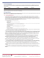
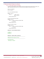
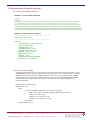
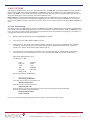
6.2.1.3.16 Receiver ID (@@Cj)
The CW12 outputs an ID message upon request. The information contained in the ID string is self-explanatory.
The model number can be used to determine the type of receiver installed. For an easy drop in replacement we
are using a model number that is specific to Motorola M12+ device. This is very useful because there would be
no update necessary for any “in house” developed software that uses the receiver’s part number. For the current
implementation the CW12 reports the following model number:
MODEL #
P283T12T11 EQV
Also there is no data for Serial Number, Manufacturing Date or Options List available. Query Receiver ID:
@@CjC<CR><LF>
where:
C = checksum
Message length: 7 bytes
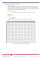
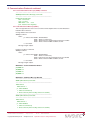
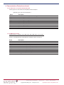
The response is output as a 25 column by 12 row array. General format is as shown below:
Figure 6 Receiver ID Binary Response Message Format
CW12 Software User Manual
Copyright ©2010 NavSync Ltd. All Rights Reserved
Page 28 of 68
Ver 12
Date: 05/07/10
Specifications subject to change without notice.
6. Communications Protocols continued
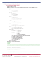
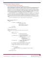
6.2.1.3.16 Receiver ID (@@Cj) continued
WinOnCore – Command Monitor Window
(Tx)@@Cj
(Rx)@@Cj
0D0A434F5059524947485420313939312D32303036204E415653594E43204C54442E20000A5346545720502F4E202
32302D4D4F5420202020202020000A534F46545741524520564552202320312E373920202020202020000A534
F4654574152452052455620232030352E30312E3030712020000A534F46545741524520444154452020446563203133
23036000A4D4F44454C202320202020503238335431325431312045515620000A4844575220502F4E202320435731322
D54494D20202020202020000A53455249414C20232020203C3C534E3E3E202020202020202020000A4D414E5546414
354555220444154452058585858585858585858000A4F5054494F4E53204C4953542020202058585858585858585858
WinOnCore – Additional Message Window
———————————————————————————
@@Cj (Receiver ID) command...
———————————————————————————
Receiver ID
COPYRIGHT 1991-2006 NAVSYNC LTD.
SFTW P/N # NS20-MOT
SOFTWARE VER # 1.79
SOFTWARE REV # 05.01.00q
SOFTWARE DATE Dec 13 2006
MODEL # P283T12T11 EQV
HDWR P/N # CW12-TIM
SERIAL # <<SN>>
MANUFACTURE DATE XXXXXXXXXX
OPTIONS LIST XXXXXXXXXX
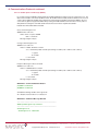
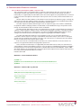
6.2.1.3.17 ASCII Position (@@Eq)
The ASCII position output message contains position, time and receiver status information similar in scope to
the @@Hb binary Short Position message. The ASCII message may be a more convenient interface for certain
applications where the ASCII output of NMEA is desired. The units and style of the data is similar to NMEA
output. As opposed to the Motorla M12 GPS receiver, the CW12 does not support DGPS (Differential GPS)
functionality hence the fields that are referring to this type of information are left blank (filled with “0”).
Default mode: Polled
Request ASCII Position Message:
@@EqmC<CR><LF>
where:
m = output mode 0x00 = output response message once (polled)
0x00 .. 0xFF = response message output at indicated rate (continuous)
1 (0x01) = once per second
2 (0x02) = once every two seconds
255 (0xFF) = once every 255 seconds
C = checksum
Message length: 8 bytes
CW12 Software User Manual
Page 29 of 68
Copyright ©2010 NavSync Ltd. All Rights Reserved
Ver 12
Date: 05/07/10
Specifications subject to change without notice.
6. Communications Protocols continued
6.2.1.3.17 ASCII Position (@@Eq) continued
Response to above command:
@@Eq,mm,dd,yy,hh,mm,ss,dd,mm.mmmm,n,ddd,mm.mmmm,w,shhhh.h, sss.s,h,m,t,dd.d,nn,rrrr,aa,CC
<CR><LF>
where:
Date:
mm = minutes 00..59
ss = seconds 00..60
UTC Time:
hh = hours 0..23
mm = minutes 00..59
ss - seconds 00..60
Latitude:
dd = degrees 00..90
mm.mmmm = minutes 00..59.9999
n = direction N = North, S = South
Longitude
ddd = degrees 000..180
mm.mmmm = minutes 00..59.9999
w = direction W = West, E = East
Height:
s = sign of height + or hhhh.h = height in meters -1000.0..18,000.0
Velocity:
sss.s = speed in knots 000.0..999.9
hhh.h = heading in degrees 000.0..359.9
Receiver status:
m = fix mode 0 = autonomous
1 = differential
t = fix type 0 = no fix
1 = 2D fix
2 = 3D fix
3 = Position Propagate Mode
dd.d = dilution of precision 00.0…99.9, HDOP if 2D, PDOP if 3D
nn = number of satellites in use 00..32
rrrr = reference station ID 0000..1023
aa = age of differential data in s 00..60
CCC = checksum 000 .. 255
Message length: 96 bytes
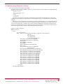
WinOnCore – Command Monitor Window
(Tx)@@Eq 00
(Rx)@@Eq
1322C31352C30362C31322C34342C30362C35322C34322E333837302C4E2C3030382C34322E333837302C572
C2B30303036332E362C3030302E332C3132372E322C302C322C31332E372C31312C303030302C30302C3031
WinOnCore – Additional Message Window
———————————————————————————
@@Eq (ASCII Position Message) command...
———————————————————————————
ASCII Position Message
,12,15,06,12,44,06,52,42.3870,N,008,42.3870,W,+00063.6,000.3,127.2,0,2,13.7,11,0000,00,01
CW12 Software User Manual
Copyright ©2010 NavSync Ltd. All Rights Reserved
Page 30 of 68
Ver 12
Date: 05/07/10
Specifications subject to change without notice.
6. Communications Protocols continued
6.2.1.3.18 Combined Position Message (@@Ga)
This message allows the user to enter an initial position estimate. If the receiver is computing a 2D fix, the
receiver will ignore any attempts to change the latitude and/or longitude using this command. If the receiver is
computing a 3D fix, it will also ignore any attempts to change height with this command. Under these conditions
the receiver will respond with coordinates of its currently calculated location.
If the user inputs the @@Ga Combined Position message along with the @@Gb Combined Time and @@Cb
Almanac Input messages to a defaulted receiver, the receiver will be in a ‘Warm Start’ condition, resulting in a
rapid TTFF. This procedure should be used with care. If any of the data is erroneous, the TTFF time may actually
be extended instead of shortened.
Default Values: Latitude = 0º
Longitude = 0º
Height = 0m (GPS Height)
Change Current Position Command:
@@GaaaaaoooohhhhtC<CR>LF>
where:
aaaa = latitude in mas -324,000,000..+324,000,000 (-90º to +90º)
oooo = longitude in mas -648,000,000..+648,000,000 (-180º to +180º)
hhhh = height -100,000..1,800,000cm (-1000 to 18000 m)
t = height type 0 = GPS, 1 = MSL (always 0 with M12+ receivers)
C = checksum
Message Length: 20 bytes
Response to above command:
@@GaaaaaoooohhhhtC<CR>LF>
where:
aaaa = latitude in mas -324,000,000..+324,000,000 (-90º to +90º)
oooo = longitude in mas -648,000,000..+648,000,000 (-180º to +180º)
hhhh = height -100,000..1,800,000cm (-1000 to 18000 m)
t = height type 0 = GPS, 1 = MSL (always 0 with M12+ receivers)
C = checksum
Message Length: 20 bytes
WinOnCore – Command Monitor Window
(Tx)@@Ga FFFFFFFFFFFFFFFFFFFFFFFFFF
(Rx)@@Ga 0B4F4141FE176FBF00001BF300
WinOnCore – Additional Message Window
———————————————————————————
@@Ga (Combined Position Message) command...
———————————————————————————
Combined Position Message
Latitude: 52.706492 degrees
Longitude: -8.894024 degrees
Height:
71.550000 m
Type: 0 (0 - GPS , 1 - MSL)
Trying to change the latitude and height gives the following result:
WinOnCore – Command Monitor Window
(Tx)@@Ga FF4F4141FE176FBF000186A000
(Rx)@@Ga 0B4F409CFE1770F10000180600
WinOnCore – Additional Message Window
———————————————————————————
@@Ga (Combined Position Message) command...
———————————————————————————
Combined Position Message
Latitude: 52.706446 degrees
Longitude: -8.893939 degrees
Height:
CW12 Software User Manual
61.500000 m
Page 31 of 68
Copyright ©2010 NavSync Ltd. All Rights Reserved
Type: 0
(0 - GPS , 1 - MSL)
Ver 12
Date: 05/07/10
Specifications subject to change without notice.
6. Communications Protocols continued
6.2.1.3.19 Combined Time Message (@@Gb)
This message allows the user to give the receiver an initial estimate of the current time and date. If the receiver has
good time synchronization (i.e. no millisecond ambiguity between the code measurements and the local TOW),
it will ignore any attempts to change the time and date parameters using this command. Rather, the receiver will
respond with currently calculated time and date.
If the user inputs the @@Gb Combined Time, @@Ga Combined Position, and @@Cb Almanac Input
message to a defaulted receiver, the receiver will be in a ‘Warm Start’ condition, resulting in a rapid TTFF. This
procedure should be used with care. If any of the data is erroneous, the TTFF time may actually be extended
instead of shortened.
Default Values: Latitude = 0º
Longitude = 0º
Height = 0m (GPS Height)
Change Current Time Message:
@@GbmdyyhmsshmC<CR>LF>
where:
Date: m = month 1…12
d = day 1…31
yy = year 1982…2100
Time: h = hours 0…23
m = minutes 0…59
s = seconds 0…59
s = signed byte of GMT offset 00 = positive 255 = negative
h = hour of GMT offset 0…+23
m = minutes of GMT offset 0…59
C = checksum
Message Length: 17 bytes
Response to above command:
@@GbmdyyhmsshmC<CR>LF>
where:
Date: m = month 1…12
d = day 1…31
yy = year 1982…2100
Time: h = hours 0…23
m = minutes 0…59
s = seconds 0…59
s = signed byte of GMT offset 00 = positive
255 = negative
h = hour of GMT offset 0…+23
m = minutes of GMT offset 0…59
C = checksum
Message Length: 17 bytes
We have 3D fix we have available data and time
WinOnCore – Command Monitor Window
(Tx)@@Gb 0FFFFFFFFFFFFFFFFFFF
(Rx)@@Gb 040D07D60B1117000000
(Tx)@@Gb 0040D07D60B111700000
(Rx)@@Gb 040D07D60B1218000000
WinOnCore – Additional Message Window
———————————————————————————
@@Gb (Combined Time Message) command...
———————————————————————————
Combined Time Message
Date: 04/13/2006
Time: 11:17:23
GMT Offset: 00h
00:00
(00h - Positive, FFh - Negative)
CW12 Software User Manual
Copyright ©2010 NavSync Ltd. All Rights Reserved
Page 32 of 68
Ver 12
Date: 05/07/10
Specifications subject to change without notice.
6. Communications Protocols continued
6.2.1.3.19 Combined Time Message (@@Gb) continued
———————————————————————————
@@Gb (Combined Time Message) command...
———————————————————————————
Combined Time Message
Date: 04/13/2006
Time: 11:18:24
GMT Offset: 00h
00:00
(00h - Positive, FFh - Negative)
6.2.1.3.20 1PPS Control Message (@@Gc)
This message allows the user to choose how the 1PPS output from the receiver will behave.
Default mode: Continuous
Change 1PPS Control Command:
@@GcpC<CR>LF>
where:
p = 1PPS control 0x00 = 1PPS disabled
0x01 = 1PPS on continuously
0x02 = 1PPS active only when tracking at least one satellite
0x03 = 1PPS on when T-RAIM conditions are met
C = checksum
Message Length: 8 bytes
Response to above command:
@@GcpC<CR>LF>
where:
p = 1PPS control 0x00 = 1PPS disabled
0x01 = 1PPS on continuously
0x02 = pulse active only when tracking at least one satellite
0x03 = 1PPS on when T-RAIM conditions are met
C = checksum
Message Length: 8 bytes
WinOnCore – Command Monitor Window
(Tx)@@Gc 0F
(Rx)@@Gc 02
(Tx)@@Gc 00
(Rx)@@Gc 00
WinOnCore – Additional Message Window
———————————————————————————
@@Gc (1PPS Control) command...
———————————————————————————
1PPS Control
1PPS Control: 2
(0 - 1PPS disabled,
1 - 1PPS on continuously,
2 - Pulse active only when tracking at least one satellite)
———————————————————————————
@@Gc (1PPS Control) command...
———————————————————————————
1PPS Control
1PPS Control: 0
(0 - 1PPS disabled,
1 - 1PPS on continuously,
2 - Pulse active only when tracking at least one satellite)
CW12 Software User Manual
Page 33 of 68
Copyright ©2010 NavSync Ltd. All Rights Reserved
Ver 12
Date: 05/07/10
Specifications subject to change without notice.
6. Communications Protocols continued
6.2.1.3.21 Position Control Message (@@Gd)
This message allows the user to choose in which positioning mode the receiver will operate.
Default mode: Continuous
Change Current Position Control Mode Message:
@@GdcC<CR>LF>
where:
c = control type 0x00 = enable normal 3D positioning
0x01 = enable position hold
0x02 = enable 2D positioning (positioning receivers only)
0x03 = enable auto-survey (timing receivers only)
C = checksum
Message Length: 8 bytes
Response to above command:
@@GdpC<CR>LF>
where:
c = control type 0x00 = enable normal 3D positioning
0x01 = enable position hold
0x02 = enable 2D positioning (positioning receivers only)
0x03 = enable auto-survey (timing receivers only)
C = checksum
Message Length: 8 bytes
WinOnCore – Command Monitor Window
(Tx)@@Gd FF
(Rx)@@Gd 00
(Tx)@@Gd 01
(Rx)@@Gd 01
WinOnCore – Additional Message Window
———————————————————————————
@@Gd (Position Control Message) command...
———————————————————————————
Position Control Message
Control Type: 1
(0 - No hold or normal positioning,
1 - Enable Position Hold,
2 - Enable Altitude Hold)
———————————————————————————
@@Gd (Position Control Message) command...
———————————————————————————
Position Control Message
Control Type: 3
(0 - No hold or normal positioning,
1 - Enable Position Hold,
2 - Enable Altitude Hold)
CW12 Software User Manual
Copyright ©2010 NavSync Ltd. All Rights Reserved
Page 34 of 68
Ver 12
Date: 05/07/10
Specifications subject to change without notice.
6. Communications Protocols continued
6.2.1.3.22 T-RAIM Select Message (@@Ge)
This message allows the user to enable or disable the Time RAIM algorithm.
Default: T-RAIM off.
Query Current Time RAIM Mode
@@GexC<CR><LF>
where:
x = one hex byte: 0xFF
C = 0xDD
Message Length: 8 bytes
Change Current Time RAIM Mode
@@GetC<CR><LF>
where:
t = mode 0x00 = disable
0x01 = enable
C = checksum
Message Length: 8 bytes
Response to either command:
@@GetC<CR><LF>
where:
t = mode 0x00 = disable
0x01 = enable
C = checksum
Message Length: 8 bytes
WinOnCore – Command Monitor Window
(Tx)@@Ge FF
(Rx)@@Ge 01
WinOnCore – Additional Message Window
———————————————————————————
@@Ge (Time RAIM Enable Message) command...
———————————————————————————
Time RAIM Enable Message
TRAIM Algorithm: 1
(0 - Disabled, 1 - Enabled)
CW12 Software User Manual
Page 35 of 68
Copyright ©2010 NavSync Ltd. All Rights Reserved
Ver 12
Date: 05/07/10
Specifications subject to change without notice.
6. Communications Protocols continued
6.2.1.3.23 T-RAIM Alarm Message (@@Gf)
This message allows the user to enter the Time RAIM alarm limit in multiples of 100 ns, or to query the receiver
for the current setting. The default alarm limit is 1000 ns.
Default value: 1000 ns
Query current T-RAIM Alarm Setting:
@@GfxxC<CR><LF>
where:
xx = two hex bytes: 0xFF 0xFF
C = 0x21
Message Length: 9 bytes
Change T-RAIM Alarm Message:
@@GfaaC<CR><LF>
where:
aa = T-RAIM alarm limit (3 – 10,000 in 100s of nanoseconds)
C = checksum
Message Length: 9 bytes
Response to either command:
@@GfaaC<CR><LF>
where:
aa = T-RAIM alarm limit (3 – 10,000 in 100s of nanoseonds)
C = Checksum
Message Length: 9 bytes
WinOnCore – Command Monitor Window
(Tx)@@Gf FFFF (query)
(Rx)@@Gf 000A
(Tx)@@Gf 000F (change)
(Rx)@@Gf 000F
WinOnCore – Additional Message Window
———————————————————————————
Time RAIM Alarm Message
TRAIM Alarm: 1000 nsec
———————————————————————————
@@Gf (Time RAIM Alarm Message) command...
———————————————————————————
Time RAIM Alarm Message
TRAIM Alarm: 1500 nsec
CW12 Software User Manual
Copyright ©2010 NavSync Ltd. All Rights Reserved
Page 36 of 68
Ver 12
Date: 05/07/10
Specifications subject to change without notice.
6. Communications Protocols continued
6.2.1.3.24 Leap Second Pending Message (@@Gj)
This command polls the receiver for leap second status information decoded from the Navigation Data message.
The output response provides specific date and time information pertaining to any future leap second addition or
subtraction. Present and future leap second values are also output rounded to the nearest integer value.
This command only operates in a polled manner, thus it must be requested each time leap second
information is desired.
The ‘present leap second value’ and ‘future leap second value’ are reported from the navigation data from
the satellites. They do not change based on the leap second application time; they will be updated based on
when the navigation data is updated.
Leap seconds are occasionally inserted in UTC and generally occur on midnight UTC June 30 or midnight
UTC December 31. The GPS control segment typically notifies GPS users of pending leap second insertions to
UTC several weeks before the event. When a leap second is inserted, the time of day will show a value of 60 in
the seconds’ field. When a leap second is removed, the date will roll over at 58 seconds.
The ‘current UTC offset’ will be zero if UTC is disabled.
Query Current Leap Second Pending Status:
@@GjC<CR><LF>
where:
C = 0x2D
Message length: 7 bytes
Response to above command:
@@GjpfyymdiffffhmsC<CR>LF>
where:
p = present leap second value
f = future leap second value
yy = year of the future leap second application
m = month of the future leap second application
d = day of the future leap second application
I = integer part of current UTC offset (seconds)
ffff = fractional part of current UTC offset (nanoseconds)
h = hour of the leap second application 0…23
m = minute of the leap second application 0…59
s = second of the leap second application 0…60
C = checksum
Message Length: 21 bytes
WinOnCore – Command Monitor Window
(Tx)@@Gj
(Rx)@@Gj 0E0E07D601010E00000000000000
WinOnCore – Additional Message Window
———————————————————————————
@@Gj (Leap Second Status) command...
———————————————————————————
Leap Second Status
Present Leap Second: 14
Future Leap Second: 14
Date of Future Leap Second (YY/M/D): 2006/01/01
UTC Offset: 14.000000000 s
Time of Leap Second Application: 00:00:00
CW12 Software User Manual
Page 37 of 68
Copyright ©2010 NavSync Ltd. All Rights Reserved
Ver 12
Date: 05/07/10
Specifications subject to change without notice.
6. Communications Protocols continued
6.2.1.3.25 Vehicle ID (@@Gk)
This message sets or defaults the ID tag. By default, the ID Tag is the 6 character serial number of the receiver.
The user may change the ID tag to any combination of six ASCII characters between 0x20 (space) to 0x7E (tilde)
that may aid in identification of a number of remote sites or vehicles. Note that space characters (0x20) may only
be used as fillers at the end of the ID tag.
Any out of range character will also cause the ID tag to remain unchanged. An ID tag modified by the user
will only be remembered through power cycles if battery back-up is provided. The ID tag is also output in the 12-channel Position/Status/Data Message (@@Ha) status message.
Change Current Vehicle ID:
@@GkvvvvvvC<CR><LF>
where:
vvvvvv = 6 ASCII ‘+’ characters: ’0x2B’ = revert to receiver serial number or
vvvvvv = 6 ASCII characters: ‘0x20’ to ‘0x7E’ to input user defined ID
C = checksum
Message length: 13 bytes
Response to above command:
@@GkvvvvvvC<CR>LF>
where:
vvvvvv = Current 6 character ID tag: ‘0x20’ to ‘0x7E’
C = checksum
Message Length: 13 bytes
WinOnCore – Command Monitor Window
(Tx)@@Gk 2A2A2A2A2A2A
(Rx)@@Gk 2A2A2A2A2A2A
WinOnCore – Additional Message Window
———————————————————————————
@@Gk (ID Tag) command...
———————————————————————————
ID Tag
Rx Serial Number: ******
CW12 Software User Manual
Copyright ©2010 NavSync Ltd. All Rights Reserved
Page 38 of 68
Ver 12
Date: 05/07/10
Specifications subject to change without notice.
6. Communications Protocols continued
6.2.1.3.26 Channel Position/Status/Data (@@Ha)
This message is the standard CW12 binary position/status message. The @@Ha message provides position and
channel related data to the user at a specified update rate.
Default mode: Polled
Request 12 Channel Position/Status/Data Message:
@@HarC<CR><LF>
where:
r = Output Rate 0x00 = output response message once (polled)
0x01 .. 0xFF = response message output at indicated rate:
0x01 = once per second
0x02 = once every two seconds
0xFF = once every 255 seconds
C = checksum
Message length: 8 bytes
Response to above command.
@@Hamdyyhmsffffaaaaoooohhhhmmmmaaaaoooohhhh mmmmVVvvhddttimsidd (repeat ‘imsidd’ series for
remaining 11 channels) ssrrccooooTTushmvvvvvv C<CR><LF>
Date:
m = month 1..12
d = day 1..31
yy = year 1998..2079
Time:
h = hours 0..23
m = minutes 00..59
s = seconds 0..60
ffff = fractional second 0..999,999,999 nanoseconds
Position (Filtered or Unfiltered following Filter Select)
aaaa = latitude in mas -324,000,000..324,000,000 (-90º..+90º)
oooo = longitude in mas -648,000,000..648,000,000 (-180º..+180º)
hhhh = GPS height in cm -100,000..+1,800,000 (-1000..+18,000m)*
mmmm MSL height in cm always 0,000,000 with M12+
Position (Always Unfiltered)
aaaa = latitude in mas -324,000,000..324,000,000 (-90º..+90º)
oooo = longitude in mas -648,000,000..648,000,000 (-180º..+180º)
hhhh = GPS height in cm -100,000..+1,800,000 (-1000..+18,000m)*
mmmm = MSL height in cm always 0,000,000 with M12+
Speed/Heading
VV = 3D speed in cm/s 0…51400 (0.0 to 514 m/s)
vv = 2D speed in cm/s 0…51400 (0.0 to 514 m/s)
hh = 2D heading 0….3599 tenths of degrees (0.0 to 359.9º)
Geometry
dd = current DOP 0 .. 999 (0.0 to 99.9 DOP) (PDOP for 3D fix, HDOP for 2D fix, )
Satellite Data
n = number of visible satellites 0 ..12
t = number of tracked satellites 0 ..12
CW12 Software User Manual
Page 39 of 68
Copyright ©2010 NavSync Ltd. All Rights Reserved
Ver 12
Date: 05/07/10
Specifications subject to change without notice.
6. Communications Protocols continued
6.2.1.3.26 Channel Position/Status/Data (@@Ha) continued
Channel Data
i = SVID 0…32
m = mode 0…8 0 = Code Search 1 = Code Acquire 2 = AGC Set 3 = Freq Acquire 4 = Bit Sync Detect
5 = Message Sync Detect
6 = Satellite Time Available
7 = Ephemeris Acquire
8 = Available for Position
s = signal strength 0…255
I = IODE 0…255
dd = channel status (16 bits)
(msb) Bit 15: Reserved
Bit 14: Reserved
Bit 13: Reserved
Bit 12: Narrow-band search mode (timing rx only)
Bit 11: Channel used for time solution
Bit 10: Differential Corrections Available
Bit 9: Invalid Data
Bit 8: Parity Error
Bit 7: Channel used for position fix
Bit 6: Satellite Momentum Alert Flag
Bit 5: Satellite Anti-Spoof Flag Set
Bit 4: Satellite Reported Unhealthy
Bits 3-0: Satellite Accuracy per para 20.3.3.3.1.3 of ICD-GPS-200
0000 (0) 0.00m <URA<=2.40m
0001 (1) 2.40m <URA<=3.40m
0010 (2) 3.40 m<URA<=4.85m
0011 (3) 4.85m<URA<=6.85m
0100 (4) 6.85m<URA<=9.65m
0101 (5) 9.65m<URA<=13.65m
0110 (6) 13.65m <URA<=24.00m
0111 (7) 24.00m<URA<=48.00m
1000 (8) 48.00m<URA<=96.00m
1001 (9) 96.00m<URA<=192.00m
1010 (10) 192.00m <URA<=384.00m
1011 (11) 384.00m <URA<=768.00m
1100 (12) 768.00m <URA<=1536.00m
1101 (13) 1536.00m <URA<=3072.00m
1110 (14) 3072.00m <URA<=6144.00m
1111 (15) 6144.00m <URA*
ss = receiver status
(msb) Bit 15-13: 111 = 3D Fix
110 = 2D Fix
101 = Propagate Mode
100 = Position Hold
011 = Acquiring Satellites
010 = Bad Geometry
001 = Reserved
000 = Reserved
CW12 Software User Manual
Copyright ©2010 NavSync Ltd. All Rights Reserved
Page 40 of 68
Ver 12
Date: 05/07/10
Specifications subject to change without notice.
6. Communications Protocols continued
6.2.1.3.26 Channel Position/Status/Data (@@Ha) continued
Channel Data continued
Oscillator and Clock Parameters:
cc = clock bias -32768…32767 ns
oooo = oscillator offset 0…250000 Hz
TT = oscillator temperature -110…250 half degrees C (-55.0…+125.0°C)
Time mode/UTC Parameters:
Bit 7: 1 = UTC time mode enabled
0 = GPS time mode enabled
Bit 6: 1 = UTC offset decoded
0 = UTC offset not decoded
Bits 5-0: Present UTC offset value, range –32…+31 seconds from GPS time* (ignore if Bit 6 = 0).
GMT Offset:
s = signed byte of GMT offset 0x00 = positive 0xFF = negative
h = hour of GMT offset 0…23
m = minute of GMT offset 0…59
vvvvvv = ID tag 6 characters (0x20 to 0x7e)
C = checksum
Message Length: 154 bytes
CW12 Software User Manual
Bit 12-11: Reserved
Bit 10: Narrow band tracking mode (timing rx only)
Bit 9: Fast Acquisition Position
Bit 8: Filter Reset To Raw GPS Solution
Bit 7: Cold Start (no almanac, almanac out of date or have almanac but time or position unknown)
Bit 6: Differential Fix
Bit 5: Position Lock
Bit 4: Autosurvey Mode
Bit 3: Insufficient Visible Satellites
Bit 2-1: Antenna Sense 00 = OK
01 = OC
10 = UC
11 = NV
Bit 0: Code Location 0 = EXTERNAL
1 = INTERNAL
rr Reserved
Page 41 of 68
Copyright ©2010 NavSync Ltd. All Rights Reserved
Ver 12
Date: 05/07/10
Specifications subject to change without notice.
Channel Data continued
6. Communications Protocols continued
6.2.1.3.26 Channel Position/Status/Data (@@Ha) continued
WinOnCore – Command Monitor Window
(Tx)@@Ha 00
(Rx)@@Ha
0C1207D60F0A0201406F400B4F4091FE1770A20000191F000000000B4F4091FE1770A20000191F000000000000000
00AE1000D0C0B10082DAF08A008082E8308A112082C5608A01B082C0A08A0130831C908A00308315408A00B082
D8B08A0150829AE08A01A08263E09A11608320508A21D00002D00201C08213608A1E000000093EFFFFFFBC9000
04E000000202020202020
WinOnCore – Additional Message Window
———————————————————————————
@@Ha (Position/Status/Data Message (12 Channel)) command...
———————————————————————————
Position/Status/Data Message (12 Channel)
Date: 12/18/2006
Time: 15:10:02.021000000
Latitude: 52.706443
Longitude: -8.893961
GPS Height: 64.310000
MSL height: 0.000000
Latitude (Unfiltered): 52.706443
Longitude (Unfiltered): -8.893961
GPS Height (Unfiltered): 64.310000
MSL height (Unfiltered): 0.000000
3D Speed: 0.000000
2D Speed: 0.000000 2D Heading: 278.500000
DOP: 1.300000
Visible Satellites: 12
Tracked Satellites: 11
*Refer to the Signal Quality Window for satellite visibility and tracking status.
Receiver Status: 0000E000h
Clock Bias: 37871
Oscillator Offset: 4294966217
Temperature: 0.000000
UTC Parameters: 4Eh
GMT Offset: 00h 00:00 (00h - Positive, FFh - Negative)
ID Tag:
CW12 Software User Manual
Copyright ©2010 NavSync Ltd. All Rights Reserved
Page 42 of 68
Ver 12
Date: 05/07/10
Specifications subject to change without notice.
6. Communications Protocols continued
6.2.1.3.27 Short Position Message (@@Hb)
This is a shortened version of the @@Ha position message provided to the user at a specified update rate.
Default mode: Polled
Request Short Position Message:
@@HbrC<CR><LF>
where:
r = output rate 0 = output response message once (polled)
1..255 = response message output at indicated rate (continuous):
0x01= once per second
0xFF = once every 255 seconds
C = checksum
Message length: 8 bytes
Response to above command.
@@HbmdyyhmsffffaaaaoooohhhhmmmmVVvvhddntssrr vvvvvvC<CR><LF>
Date:
m = month 1..12
d = day 1..31
yy = year 1998..2079
Time:
h = hours 0..23
m = minutes 00..59
s = seconds 0..60
ffff = fractional second 0..999,999,999 nanoseconds
Position (Filtered or Unfiltered following Filter Select)
aaaa = latitude in mas -324,000,000..324,000,000 (-90º..+90º)
oooo = longitude in mas -648,000,000..648,000,000 (-180º..+180º)
hhhh = GPS height in cm -100,000..+1,800,000 (-1000..+18,000m)*
mmmm MSL height in cm always 0,000,000 with M12+
Speed/Heading
VV = 3D speed in cm/s 0…51400 (0.0 to 514 m/s)
vv = 2D speed in cm/s 0…51400 (0.0 to 514 m/s)
hh = 2D heading 0….3599 tenths of degrees (0.0 to 359.9º)
Geometry
dd =current DOP 0..999 (0.0 to 99.9 DOP) (PDOP for 3D fix, HDOP for 2D fix, 00.0 otherwise)
Satellite Data
n = number of visible satellites 0…12
t = number of tracked satellites 0…12
ss receiver status
(msb) Bits 15-13: 111 = 3D Fix
110 = 2D Fix
101 = Propagate Mode
100 = Position Hold
011 = Acquiring Satellites
010 = Bad Geometry
001 = Reserved
000 = Reserved
CW12 Software User Manual
Page 43 of 68
Copyright ©2010 NavSync Ltd. All Rights Reserved
Ver 12
Date: 05/07/10
Specifications subject to change without notice.
6. Communications Protocols continued
6.2.1.3.27 Short Position Message (@@Hb) continued
Bits 12-11: Reserved
Bit 10: Receiver in narrow-band tracking mode
Bit 9: Fast Acquisition Position
Bit 8: Filter Reset To Raw GPS Solution
Bit 7: Cold Start (no almanac, almanac out of date or have almanac but time or position unknown)
Bit 6: Differential Fix
Bit 5: Position Lock
Bit 4: Autosurvey Mode
Bit 3: Insufficient Visible Satellites
Bits 2-1: Antenna Sense 00 = OK
01 = Over current
10 = Undercurrent
11 = No bias voltage
Bit 0: Code Location 0 = EXTERNAL
1 = INTERNAL
rr Reserved
vvvvvv = ID tag 6 characters (0x20 to 0x7e)
C = checksum
Message Length: 54 bytes
WinOnCore – Command Monitor Window
(Tx)@@Hb 00
(Rx)@@Hb 0C1207D611051C01AB3F000B4F40F5FE1770B8000017AA0000000000000000003B00140A08E00
00000202020202020
WinOnCore – Additional Message Window
———————————————————————————
@@Hb (Short Position Data) command...
———————————————————————————
Short Position Data
Date: 12/18/2006
Time: 17:05:28.028000000
Latitude: 52.706471
Longitude: -8.893955
GPS Height: 60.580000
MSL Height: 0.000000
3D Speed: 0.000000
2D Speed: 0.000000
2D Heading: 5.900000
DOP: 2.000000
Visible Satellites: 10
Tracked Satellites: 8
Receiver Status: E000h
ID Tag:
CW12 Software User Manual
Copyright ©2010 NavSync Ltd. All Rights Reserved
Page 44 of 68
Ver 12
Date: 05/07/10
Specifications subject to change without notice.
6. Communications Protocols continued
6.2.1.3.28 Channel Time RAIM Status Message (@@Hn)
This message allows the user to request output of T-RAIM status information.
When the T-RAIM algorithm is enabled with the @@Ge01 command, the CW12 bases the reported T-RAIM Status
and Solution in the @@Hn command from the number of satellites tracked and the 1-sigma timing accuracy
estimate (TACC). The CW12 is capable of removing faulty satellites from the solution if the number of satellites in
the solution is 5 or more. So the T-RAIM Status is 0 (detection and isolation possible) when the number of visible
satellites is 5 or more. The receiver can continue to detect faulty satellites while the number of visible satellites is
3 or more. So when the number of visible satellites is 3, 4, or 5, the T-RAIM Status is 1 (detection only possible).
Finally if number of visible satellites is 2 or fewer, the T-RAIM Status is 2 (neither possible).
When the T-RAIM Status is 0 or 1, the T-RAIM Solution is determined by a comparison of the 1-sigma timing
error estimate and the Alarm Threshold set with the @@Gf command. When the T-RAIM Status is 2, the T-RAIM
Solution is 2 (unknown). The T-RAIM Solution is 0 (OK) when the Alarm Threshold is less than four times the
one sigma Accuracy estimate. Four times the one sigma Accuracy estimate was chosen because a +/- 4-sigma
confidence interval is equivalent to the 99.99% detection and isolation probability of the T-RAIM algorithm in the
CW12.
This is for a normal distribution, which is a valid assumption for the GPS timing errors.
Request Current Time RAIM Status:
@@HnrC<CR><LF>
where:
r = output rate 0 = polled once
1 .. 255 = output at indicated rate:
0x01 = once per second
0x02 = once per every 2 seconds
0xFF = once per 255 seconds
C = checksum
Message Length: 8 bytes
Response to above command:
@@Hnpysrvvvveensffff (repeat sffff for remaining 11channels)C<CR><LF>
where:
p = pulse status 0 = off
1 = on
y = 1PPS pulse sync 0 = pulse referenced to UTC,
1 = pulse referenced to GPS time
s = Time RAIM Solution 0 = solution within alarm limits;
1 = ALARM, user-specified limit exceeded
2 = UNKNOWN, due to:
a. alarm threshold set too low
b. T-RAIM turned off
c. insufficient tracked satellites
r = Time RAIM status 0 = detection and isolation possible;
1 = detection only possible;
2 = neither possible
vvvv = 32 bit field to indicate which svids were removed by T-RAIM
ee = time solution one sigma accuracy 0..65535 nsec estimate
n = negative sawtooth time error –128..+127 ns of next pulse
For each of 12 channels:
s = satellite id 1 .. 32
ffff = fractional GPS local time 0..999999999 ns estimate of satellite
C = checksum
Message Length: 78 bytes
CW12 Software User Manual
Page 45 of 68
Copyright ©2010 NavSync Ltd. All Rights Reserved
Ver 12
Date: 05/07/10
Specifications subject to change without notice.
6. Communications Protocols continued
6.2.1.3.28 Channel Time RAIM Status Message (@@Hn) continued
WinOnCore – Command Monitor Window
(Tx)@@Hn 00
(Rx)@@Hn 0100000000000000001A0019012D0E8715012D0E740A012D0E8203012D0E870D0
12D0E8317012D0E8A07012D0E8F06012D0E8B000000000010012D0E7800000000001F012D0E85
WinOnCore – Additional Message Window
———————————————————————————
@@Hn (12-Channel Time RAIM Status Message) command...
———————————————————————————
12-Channel Time RAIM Status Message
pulse status 1
pulse sync 0
solution status 0
traim status 0
svids removed 0000h
sigma accuracy 26
sawtooth error 0
Ch SVID Fractional Time Estimate (ns)
01 25 19730055
02 21 19730036
03 10 19730050
04 3 19730055
05 13 19730051
06 23 19730058
07 7 19730063
08 6 19730059
09 0 0
10 16 19730040
11 0 0
12 31 19730053
CW12 Software User Manual
Copyright ©2010 NavSync Ltd. All Rights Reserved
Page 46 of 68
Ver 12
Date: 05/07/10
Specifications subject to change without notice.
6. Communications Protocols continued
6.2.1.3.29 12 Channel Self-Test Message (@@Ia)
The CW12 receiver user has the ability to perform an extensive self-test. The tests that are accomplished during
the Self-Test are as follows:
• Antenna connection
• RTC communication and time
• Temperature sensor
• RAM
• FLASH ROM
• Correlator IC
The output of the self-test command is a 24-bit field, where each bit of the field represents the Pass/Fail
condition for each parameter tested. Passed tests are indicated by a logic ‘1’, while failed tests are indicated by
a logic ‘0’.
When the self-test is initiated, the next output message may not be the response. The self-test may take up
to ten seconds to execute. Once the self-test is complete, the satellite acquisition process restarts as when the
receiver was first powered on. The date, time, position, almanac and ephemeris information is all retained. The
CW12 has very limited support for this command; however the bit descriptions for the reply message have been
kept in order to preserve the consistency with the Motorola M12 user manual.
Response to above command:
@@IasssC<CR>LF>
where:
sss = self test results
(msb) Bits 23-22: Antenna Sense (currently not supported – work in progress)
00 = OK
01 = Overcurrent
10 = Undercurrent
11 = No bias voltage present
Bit 21: RTC comm & time (not supported)
Bit 20: Temperature Sensor (not supported)
Bit 19: spare
Bit 18: RAM (not supported)
Bit 17: ROM
Bit 16: 1 KHz presence (not supported)
Bit 15: spare
Bit 14: Temperature Sensor (not supported)
Data Checksum
Bit 13: Oscillator Data Checksum (not supported)
Bit 12: Manufacturing Data Checksum (not supported)
Bit 11: Channel 12 correlator test (not supported)
Bit 10: Channel 11 correlator test (not supported)
Bit 9: Channel 10 correlator test (not supported)
Bit 8: Channel 9 correlator test (not supported)
Bit 7: Channel 8 correlator test (not supported)
Bit 6: Channel 7 correlator test (not supported)
Bit 5: Channel 6 correlator test (not supported)
Bit 4: Channel 5 correlator test (not supported)
Bit 3: Channel 4 correlator test (not supported)
Bit 2: Channel 3 correlator test (not supported)
Bit 1: Channel 2 correlator test (not supported)
Bit 0: Channel 1 correlator test (not supported)
C = checksum
Message Length: 10 bytes
CW12 Software User Manual
Page 47 of 68
Copyright ©2010 NavSync Ltd. All Rights Reserved
Ver 12
Date: 05/07/10
Specifications subject to change without notice.
6. Communications Protocols continued
6.2.1.3.29 12 Channel Self-Test Message (@@Ia) continued
WinOnCore – Command Monitor Window
(Tx)@@Ia
(Rx)@@Ia 377FFF
WinOnCore – Additional Message Window
———————————————————————————
@@Ia (Self-Test Message (12 Channel)) command...
———————————————————————————
Self-Test Message (12 Channel)
Self Test Byte 1: 37h
Self Test Byte 2: 7Fh
Self Test Byte 3: FFh
6.2.1.3.30 System Power-On Failure (@@Sz)
Immediately after power-up, the CW12’s ROM is tested. If this test does not pass, the firmware will not execute
its positioning algorithms. Rather, it will continuously output this message once every 10 seconds. Receipt of
this message indicates that the receiver will need to be repaired and/or reprogrammed. This feature keeps the
receiver from being utilized when the ROM has been compromised, and therefore unreliable, helping to protect
the integrity of the application.
@@SzcC<CR><LF>
where:
c = constant equal to 0
C = checksum
Message length: 8 bytes
CW12 Software User Manual
Copyright ©2010 NavSync Ltd. All Rights Reserved
Page 48 of 68
Ver 12
Date: 05/07/10
Specifications subject to change without notice.
6. Communications Protocols continued
6.2.2 NMEA Messages
There are two main types of sentences, ‘Approved’ and ‘Proprietary’. All sentences start with $ delimited with commas and ending with <CR><LF>. Approved sentences are recognized by the first 5 characters after the $, which define both the kind of talker
providing the information (2 characters, GP in the case of a GPS), and the type of information (3 characters). Proprietary sentences are indicated by a P following the $, as the first of the 5 characters, the next 3 indicating the manufacturer (from a listing
of mnemonic codes), and the 5th character being selected by that manufacturer for the particular sentence structure. Proprietary sentences must conform with the general NMEA structures, but are otherwise undefined outside of the Manufacturers own
documentation.
The following Approved messages are available from the CW12 receiver:
GPGLL - Geographic Position - Latitude and Longitude
GPGGA - Global Positioning System Fix Data
GPGSA - GNSS DOP and Active Satellites
GPGSV - GNSS Satellites in View
GPRMC – Minimum required sentence
The following proprietary messages are disabled from the standard build but can be made available later on for special builds:
POLYA – GPGGA with additional estimated accuracy
POLYP – NavSync proprietary status message
POLYS – NavSync Proprietary satellite status message (GPGGA + GPGSV)
POLYI - NavSync Proprietary net assist information message
6.2.2.1 GLL, Geographic position, Lat/Lon.
Latitude and longitude, with time of position fix and status.
$GPGGL, Latitude , N ,Longitude , hhmmss.ss,Status*cs
Name
Description
$GPGGA
Latitude
N Longitude
E hhmmss.ss
Status
cs NMEA sentence header (Position Data)
User datum latitude degrees, minutes, decimal minutes format (ddmm.mmmmm)
Hemisphere ‘N’= North, or ‘S’ = South
User datum longitude degrees, minutes, decimal minutes format (dddmm.mmmmm)
Longitude Direction ‘E’= East, or ‘W’ = West
UTC Time in hours, minutes, seconds. and decimal seconds format.
StatusV=navigation receiver warning, A=data valid
Message checksum in hexadecimal
CW12 Software User Manual
Page 49 of 68
Copyright ©2010 NavSync Ltd. All Rights Reserved
Ver 12
Date: 05/07/10
Specifications subject to change without notice.
6. Communications Protocols continued
6.2.2.2 GGA, GPS fix data
Time and position, together with GPS fixing related data (number of satellites in use, and the resulting HDOP, age of
differential data if in use, etc.).
$GPGGA, hhmmss.ss , Latitude , N ,Longitude , E , FS , NoSV , HDOP , Altref , m , msl , m, DiffAge , DiffStation*cs
Name
Description
$GPGGA
hhmmss.ss
Latitude
N/S Longitude
E FS NoSV
HDOP
Altmsl
M MSLcorr
m DiffAge
DiffStation
cs NMEA sentence header (Position Data)
UTC Time in hours, minutes, seconds. and decimal seconds format.
User datum latitude degrees, minutes, decimal minutes format (ddmm.mmmmm)
Hemisphere ‘N’= North, or ‘S’ = South
User datum longitude degrees, minutes, decimal minutes format (dddmm.mmmmm)
Longitude Direction ‘E’= East, or ‘W’ = West
Fix Status:0 No fix1 Standard GPS2 Differential GPS
Number of satellites used in the position solution
2-D Horizontal Dilution of Precision (00.0 to 99.9)
Antenna altitude above/below mean sea level (WGS84 geoid)
Units of height (meters)
Geoidal separation, user datum mean sea level correction (Diff. between WGS-84 earth
ellipsoid and mean sea level. “-” sign means that geoid is below WGS-84 ellipsoid)
Units of height (meters)
Age of differential correction
Differential base station ID
Message checksum in hexadecimal
6.2.2.3 GSA, GPS DOP and Active satellites
GPS receiver operating mode, satellites used for navigation, and DOP values.
$GPGSA,Smode,FS,sv,sv,sv,sv,,,,,,,,PDOP,HDOP,VDOP*cs
Name
Description
$GPGSA
Smode
FS sv HDOP
VDOP
PDOP
cs NMEA sentence header (Satellite Data)
A= Automatic switching 2D/3D M=Manually fixed 2D/3D)
Fix Status:
0 No fix
1 Standard GPS
Satellites in use, null for unused fields
2-D Horizontal Dilution of Precision (00.0 to 99.9)
Vertical Dilution of Precision (00.0 to 99.9).
3-D Position Dilution of Precision (00.0 to 99.9)
Message checksum in hexadecimal
CW12 Software User Manual
Copyright ©2010 NavSync Ltd. All Rights Reserved
2 Differential GPS
Page 50 of 68
Ver 12
Date: 05/07/10
Specifications subject to change without notice.
6. Communications Protocols continued
6.2.2.4 GSV, GPS Satellites in View
The number of satellites in view, together with each PRN, elevation and azimuth, and C/No value. Only four satellite
details are transmitted in one message, there being up to three messages used as indicated in the first field.
$GPGSV, NoMsg, MsgNo, NoSv,sv,elv,az,cno{,sv,elv,az,cno….}*cs
Name
$GPGSV
NoMsg
MsgNo
sv elv az cno cs Description
NMEA sentence header (Satellite Data)
Total number of GPGSV messages being output
Number of this message
Satellites ID
Satellite elevation angle (degrees)
Satellite azimuth angle (degrees)
Satellite signal/Noise ration (dB/Hz)
Message checksum in hexadecimal
Number of messages (maximum 3)
6.2.2.5 RMC, Recommended Minimum data
The ‘Recommended Minimum’ sentence defined by NMEA for GPS/Transit system data. The use of a checksum field is
mandatory.
$GPRMC,hhmmss,status,latitude,N,longitude,W,spd,cmg,ddmmyy,mv,*cs
Name
Description
$GPRMC
hhmmss
status
Latitude
N Longitude
E spd cmg
hhmmss
mv cs NMEA sentence header (Recommended Minimum Sentence)
UTC Time in hours, minutes, seconds.
StatusV=navigation receiver warning, A=data valid
User datum latitude degrees, minutes, decimal minutes format (ddmm.mmmmm)
Hemisphere ‘N’= North, or ‘S’ = South
User datum longitude degrees, minutes, decimal minutes format (dddmm.mmmmm)
Longitude Direction ‘E’= East, or ‘W’ = West
Speed over ground (knots).
Course made good
Date in Day, Month Year format
Magnetic variation
Message checksum in hexadecimal
CW12 Software User Manual
Page 51 of 68
Copyright ©2010 NavSync Ltd. All Rights Reserved
Ver 12
Date: 05/07/10
Specifications subject to change without notice.
6. Communications Protocols continued
6.2.2.6 VTG, Course over ground and Ground speed
Velocity is given as Course Over Ground (COG) and Ground Speed
$GPVTG,cogt,T,cogm ,M ,knots,N,kph,K*cs
Name
Description
$GPVTG
cogt
T cogm
M knots
N kph K cs NMEA sentence header (Speed and heading)
Course over ground (true)
True - fixed field Course over ground (magnetic)
Magnetic - fixed field Speed over ground (knots)
Knots - fixed field Speed over ground (kph)
kph – fixed field Message checksum in hexadecimal
6.2.2.7 POLYT, Time of Day
$POLYT,hhmmss.ss,ddmmyy, UTC_TOW ,week, GPS_TOW ,Clk_B , Clk_D ,PG,cs
$POLYT,123456.00,250299,123456.00,0978,123456.00,123456,123.456,28,cs
Name
Description
$POLYT
hhmmss.ss
ddmmyy
UTC_TOW
week GPS_TOW
Clk_B
Clk_D
PG cs NavSync Proprietary NMEA sentence header (Position Data)
UTC Time in hours, minutes, seconds. and decimal seconds format.
Date in day, month, year format.
UTC Time of Week (seconds)
GPS week number (continues beyond 1023)
GPS Time of Week (seconds)
Receiver clock Bias (nanoseconds)
Receiver clock Drift (nanoseconds/second)
1PPS Granularity (nanoseconds)
Message checksum in hexadecimal
CW12 Software User Manual
Copyright ©2010 NavSync Ltd. All Rights Reserved
Page 52 of 68
Ver 12
Date: 05/07/10
Specifications subject to change without notice.
6. Communications Protocols continued
6.2.2.8 POLYP, Position Data
$POLYP,hhmmss.ss, Latitude ,N, Longitude ,E, AltRef ,FS,Hacc,Vacc, SOG , COG , Vvel ,ageC,HDOP,VDOP,PDOP,
TDOP,GU,RU,DR,cs
$POLYP,123456.00,5214.12345,N,00056.12345,W,00138.80,G3,0002,0002,021.21,180.00,+003.96,99.9,01.1,01
.6,01.9,01.7,07,00,00,cs
Name
Description
$POLYP
hhmmss.ss
Latitude
N
Longitude
E
AltRef
FS Hacc Vacc SOG COG V_vel
ageC
HDOP
VDOP
PDOP
GDOP
TDOP
GU RU DR cs NavSync Proprietary NMEA sentence header (Position Data)
UTC Time in hours, minutes, seconds. and decimal seconds format.
User datum latitude degrees, minutes, decimal minutes format (ddmm.mmmmm)
Hemisphere ‘N’= North, or ‘S’ = South
User datum longitude degrees, minutes, decimal minutes format (dddmm.mmmmm)
Longitude Direction ‘E’= East, or ‘W’ = West
Altitude (meters) above user datum ellipsoid.
Fix Status:
NF No Fix DR Predictive Dead Reckoning solution
DA Predictive Dead Reckoning solution with DR aiding
G1 Partial GPS solution with DR aiding
G2 Stand alone 2D solution
G3 Stand alone 3D solution
D1 Partial Differential GPS solution with DR aiding
D2 Differential 2D solution
D3 Differential 3D solution
Horizontal (2 sigma) accuracy estimates. (0 to 9999 meters)
Vertical (2 sigma) accuracy estimates. (0 to 9999 meters)
Speed Over Ground (knots) (000.00 to 999.99 knots)
Course Over Ground (true) in degrees (000.00 to 359.99 degrees)
Vertical (positive Up) velocity (m/s) (000.00 to 999.99 m/s)
Age of most recent DGPS Corrections applied (seconds).(00.0 to 99.9 = none available)
2-D Horizontal Dilution of Precision (00.0 to 99.9)
Vertical Dilution of Precision (00.0 to 99.9).
3-D Position Dilution of Precision (00.0 to 99.9)
4-D Geometric Dilution of Precision (00.0 to 99.9)
Time Dilution of Precision (00.0 to 99.9)
Number of GPS satellites used in the navigation solution
Number of GLONASS satellites used in the navigation solution
Dead Reckoning aiding status bits (in ASCII Hex)
bit 0
Altitude Position Aiding applied
bit 1
Vertical Velocity Aiding applied
bit 2
(GPS-GLONASS) time difference aiding applied
bit 3
External Distance travelled input used
bit 4
External Speed input used
bit 5
External Track input used
bit 6
External Delta-Track input used.
bit 7-8
Reserved for future usee
Message checksum in hexadecimal
CW12 Software User Manual
Page 53 of 68
Copyright ©2010 NavSync Ltd. All Rights Reserved
Ver 12
Date: 05/07/10
Specifications subject to change without notice.
6. Communications Protocols continued
6.2.2.9 POLYU, UTM Position Data
This message is only available in enhanced software versions.
$POLYP,hhmmss.ss, Easting ,E, Northing ,N,
AltMSL ,FS,Hacc,Vacc, SOG , COG , Vvel, ZageC, HDOP ,VDOP ,PDOP ,TDOP ,GU ,RU ,DR ,cs
$POLYP,123456.00,1234567.123,W,1234567.123,N,00138.80,G3,0002,0002,021
.21,180.00,+003.96,99.9,01.1,01.6,01.9,01.7,07,00,00,cs
The $POLYU is a UTM (Universal Transverse Mercator projection) version of the $POLYP sentence.
6.2.2.10 POLYG, Local Grid Position Data
This message is only available in enhanced software versions.
$POLYP,hhmmss.ss, Easting ,E, Northing ,N, AltMSL ,FS,Hacc,Vacc, SOG , COG , Vvel ,ageC,HDOP,VDOP,PDOP
,TDOP,GU,RU,DR,cs
$POLYP,123456.00,1234567.123,W,1234567.123,N,00138.80,G3,0002,0002,021.21,
180.00,003.96,99.9,01.1,01.6,01.9,01.7,07,00,00,cs
The $POLYG is the same as the $POLYU sentence, except that the UTM position has been shifted to a Local Grid
position by applying a Easting, Northing and Height offsets. The position output will be exactly the same as the UTM
position if the Local Grid has not been defined.
6.2.2.11 POLYS, Satellite Status
$POLYS,GT,ID,s,AZM,EL,SN,LK,ID,s,AZM,EL,SN,LK,ID,
s,AZM,EL,SN,LK,ID,s,AZM,EL,SN,LK,ID,s,AZM,EL,SN,
LK,...,cs
$POLYS,05,03,U,103,56,48,99,23,U,225,61,39,99,16,
U,045,02,41,99,26,U,160,46,50,32,30,-,340,04,50,
00,cs
Name
Description
$POLYS
NavSync Proprietary NMEA sentence header (Satellite Data)
GT Number of GPS satellites tracked
ID Satellite PRN number (1-32)
s
Satellite status
-
= not used
U
= used in solution
e
= available for use, but no ephemeris
AZM Satellite azimuth angle (range 000 - 359 degrees)
EL Satellite elevation angle (range 00 - 90 degrees)
SN Signal to noise ratio in (range 0 - 55 dBHz)
LK Satellite carrier lock count (range 0 - 255 seconds)
0
= code lock only
255
= lock for 255 or more seconds
cs Message checksum in hexadecimal
CW12 Software User Manual
Copyright ©2010 NavSync Ltd. All Rights Reserved
Page 54 of 68
Ver 12
Date: 05/07/10
Specifications subject to change without notice.
6. Communications Protocols continued
6.2.2.12 POLYI, Additional Information Message
$POLYI,JN,jammer,EXT,efields,INT,ifields,cs
$POLYI,JN,12,EXT,HPOS,VPOS,INT,CLKB
Name
Description
$POLYI
JN jammer
EXT efields
INT ifieldsTSYNC NavSync Proprietary NMEA sentence header (Additional Information)
Fixed descriptor field
Detected Jammer to Noise Ratio [dBHz]
Fixed descriptor field, indicates the use of externally provided ancillary measurements e.g.
received from Network Assistance. All comma separated efields following, up to the INT field descriptor, are externally provided measurements
DIFF = Differential Inputs
TSYNC = Time synchronization
CLKB = Clock Bias
FREQ = Frequency (of reference oscillator)
HPOS = Horizontal position VPOS = Vertical Position (altitude)
VVEL = Vertical Velocity
DIST = Distance Moved
SPEED = Current Speed
TRACK = Current track
DTRACK = Delta track (change in direction)
Fixed descriptor field, indicates the use of internally provided ancillary measurements e.g.
retrieved from non volatile memory. All comma separated ifields following, up to the INT
field descriptor, are internally provided measurements
= Time synchronization
CLKB = Clock Bias
FREQ = Frequency (of reference oscillator)
HPOS = Horizontal position VPOS = Vertical Position (altitude)
VVEL = Vertical Velocity
DIST = Distance Moved
SPEED = Current Speed
TRACK = Current track
DTRACK = Delta track (change in direction)
CW12 Software User Manual
Page 55 of 68
Copyright ©2010 NavSync Ltd. All Rights Reserved
Ver 12
Date: 05/07/10
Specifications subject to change without notice.
6. Communications Protocols continued
6.2.3 Proprietary Commands
The NavSync CW12 receiver has a unique set of proprietary commands.
Commands will only be accepted on UART 1, if NMEA protocol is enabled on this port (this option is available in enhanced versions).
The commands to and from the unit have the following general formats:
$PRTH<Q|S|R>,<id>,<msg fields>[*<checksum>]<cr><lf>
Where:
<S|Q|R> is the single ASCII character as follows:
S: Command, requires the CW12 receiver to Set system settings.
Q: Command, a Query command to the CW12 receiver.
R: Response, an CW12 receiver or Response to a $PRTH Query or an acknowledgment of a $PRTH Set.
<id> is a 4 character command identifier.
<msg fields> are the message fields for the message and are all positional. Optional or unknown fields are shown as nulls (ie
adjacent commas). Trailing commas to the end of a message (ie nothing but null message fields) are not required.
*<checksum> An optional checksum byte for checking accuracy defined as follows:
The checksum is displayed as a pair of ASCII characters, (0-9 and A-F inclusive) whose value represents the “HEX” value of
the checksum byte. When used, it always appears as the last field of the sentence and is prefixed by field delimiter “*” (HEX 2A)
instead of “,” and followed by <CR><LF> (HEX 0D 0A). The checksum value is calculated by XOR’ing (exclusive OR’ing also
known as Modulo 2 Sum) the 8 binary data bits of each valid data character in the sentence between the “$” (HEX 24) and “*”
(HEX 2A) characters.
The “$” (HEX 24) and the “*” (HEX 2A) characters are not included in the checksum.
<cr><lf> are the ASCII codes 0Dh and 0Ah (carriage return and line feed) respectively.
Some commands use multiple sentences to transfer data: multiple sentence transfer shall be accomplished by means of 2 fields
within the sentence for which this format is used:
t: Total number of sentences forming the data transfer (minimum value 1)
x: ID number of the current sentence ranging from 1 to t inclusive
Null fields within a command shall be interpreted as “use current value” where appropriate. Null fields must be delimited by adjacent commas when they exist between two non-null fields. If all trailing fields after a given field are null, further commas are not
required.
6.2.3.1 PRTH<Q|S|R>,DRL M:
DEAD RECKONING LIMIT
Purpose
This message Sets, Queries and Responds to the limit for the forward predictive Dead Reckoning, after the last valid
fix (epochs). The dead reckoning will progress at constant velocity for the first half of this period and then reduce to a
standstill during the second half.
Query Format
$PRTHQ,DRLM[*checksum]<cr><lf>
Set Format
$PRTHS, DRLM,DR_Limit[*checksum]<cr><lf>
Response / Acknowledge Format
$PRTHR, DRLM, DR_Limit*<checksum><cr><lf>
Explanation of Parameters
DR_Limit
Number of epochs to dead reckon for (integer, range 0 –32768)
CW12 Software User Manual
Copyright ©2010 NavSync Ltd. All Rights Reserved
Page 56 of 68
Ver 12
Date: 05/07/10
Specifications subject to change without notice.
6. Communications Protocols continued
6.2.3.2 PRTH<Q|S|R>,ILLH:
INITIALIZED LAT, LONG, HEIGHT POSITION
Purpose
This message Sets, Queries and Responds to the initialized geodetic position (latitude, longitude, ellipsoidal height
and antenna height above the reference marker) in the receiver’s current user datum.
The position RMS accuracy is used to decide how much importance to put on the input values and should be set with
care.
Query Format
$PRTHQ,ILLH[*checksum]<cr><lf>
Set Format
$PRTHS,ILLH,LatDeg,LatMin,LatSec,LatH,LonDeg,LonMin,LonSec,LonH,EllHt,AntHt,posRMS [*checksum]<cr><lf>
Response / Acknowledge Format
$PRTHR,ILLH,LatDeg,LatMin,LatSec,LatH,LonDeg,LonMin,LonSec,LonH,EllHt,AntHt,posRMS*<checksum><cr><lf>
Explanation of Parameters
LatDeg Latitude degrees (floating point, range ±90.0)
LatMin Latitude minutes (floating point, range ±59.999999)
LatSec Latitude seconds (floating point, range ±59.99999)
LatH
Latitude hemisphere (char ‘N’ or ‘S’)
LonDeg Longitude degrees (floating point, range ±90.0)
LonMin Longitude minutes (floating point, range ±59.999999)
LonSec Longitude seconds (floating point, range ±59.99999)
LonH Longitude hemisphere (char ‘E’ or ‘W’)
EllHt
Height of the reference marker above the current user datum reference ellipsoid in meters (floating point, range ±18,000.0)
AntHt Height of the antenna phase center above the reference marker height defined by EllHt above in meters (floating point, range ±18,000.0)
posRMSRMS accuracy of the input position (meters) (floating point, range 0 - 999999.0)
Note that since the Degree, Minutes and Seconds fields will accept floating point values then a decimal degree value, or and
integer degree, decimal minute value can be input directly by setting the minutes and seconds fields to zero as appropriate (eg 52.12345678,0,0,N or 52,14.123456,0,N). 6.2.3.3 PRTH<Q|S|R>,ITIM:
INITIALIZE TIME AND DATE
Purpose
This message Sets, Queries and Responds to the user initialized time and date. Two input options are available, one
allowing a calendar date and GMT time to be input and the other a GPS week number and seconds of week.
The input date is acted upon regardless and is primarily used to set the GPS week inside the receiver. The
time input will not be used if is set to zero, or if the receiver is currently tracking any satellites and therefore already has
a good sub-millisecond knowledge of time.
If the time input is not used then the Response message returns the values used or assumed instead of those
input. The time RMS accuracy is used to decide how much importance to put on the input values and should be set
with care.
Query Format
$PRTHQ,ITIM[*checksum]<cr><lf>
Set Format
Using a GMT time format
$PRTHS,ITIM,timeRMS,GMT,day,month,year,[hours],[minutes],[seconds]
[*checksum]<cr><lf>
Using a GPS time format
$PRTHS,ITIM,timeRMS,GPS,gps_week,[gps_time][*checksum]<cr><lf>
Response / Acknowledge Format
$PRTHR,ITIM,timeRMS,GMT,day,month,year,hours,minutes,seconds,GPS,
gps_week,gps_time*<checksum><cr><lf>
CW12 Software User Manual
Page 57 of 68
Copyright ©2010 NavSync Ltd. All Rights Reserved
Ver 12
Date: 05/07/10
Specifications subject to change without notice.
6. Communications Protocols continued
6.2.3.3 PRTH<Q|S|R>,ITIM:
INITIALIZE TIME AND DATE continued
Explanation of Parameters
time RMS
RMS accuracy of the input time-tag (seconds) (floating point, range 0 – 999999.0).
day
day of month (integer, range 1 – 31).
month month of year (integer, range 1 – 12).
year
4 digit year (integer, range 1980 – 2047).
hours hours of day (integer, range 0 – 23).
minutes minutes of hour (integer, range 0 – 59).
seconds
seconds of minute (floating point, range 0 – 59.999).
gps_week
GPS week number, including pre GPS roll-over weeks, eg 1037 (integer, range 0 – 32768)
gps_TOW
GPS Time of Week in seconds (floating point, range 0.0 –604800.0).
6.2.3.4 PRTH<Q|S|R>, MMSV: MIN & MAX SATELLITES FOR A POSITION SOLUTION
Purpose
This message Sets, Queries and Responds to the minimum and maximum number of satellites the receiver will use
for a position solution. Increasing the minimum number of satellites will improve the accuracy achieved when sufficient
satellites are available, but may reduce the time when a solution can be produced. Reducing the maximum number of
satellites may reduce the accuracy of the position solution, but will decrease the amount of processing power required
for the solution.
Note that setting the Maximum satellites to less than 4 will prevent the receiver from performing a 3D position solution. Likewise setting the minimum number of satellites greater than 3 will prevent the receiver performing a 2-D, altitude
fixed solution.
The maximum must be greater than or equal to the minimum number of satellites.
Query Format
$PRTHQ,MMSV[*checksum]<cr><lf>
Set Format
$PRTHS,MMSV,[min_NSV],[max_NSV][*checksum]<cr><lf>
Response / Acknowledge Format
$PRTHR,MMSV,min_NSV,max_NSV*<checksum><cr><lf>
Explanation of Parameters
min_NSV
Minimum Satellites used for a position / time solution, (integer, range 0-12)
max_NSV
Maximum Satellites used for a position / time solution, (integer, range 0-12)
6.2.3.5 PRTH<Q|S|R>,MCNO:
MINIMUM SIGNAL CNO
Purpose
This message Sets, Queries and Responds to the satellite tracking minimum signal to noise ratio (C/No) required for
inclusion into the navigation solution.
Query Format
$PRTHQ,MCNO[*checksum]<cr><lf>
Set Format
$PRTHS,MCNO,min_CNO[*checksum]<cr><lf>
Response / Acknowledge Format
$PRTHR,MCNO,min_CNO*<checksum><cr><lf>
Explanation of Parameters
min_CNO
the minimum satellite tracking C/No required for inclusion into the navigation solution (integer, range 0 – 60 dBHz).
CW12 Software User Manual
Copyright ©2010 NavSync Ltd. All Rights Reserved
Page 58 of 68
Ver 12
Date: 05/07/10
Specifications subject to change without notice.
6. Communications Protocols continued
6.2.3.6 PRTH<Q|S|R>,DYNA:
RECEIVER DYNAMICS
Purpose
This message Sets, Queries and Responds to the receiver host dynamics and hence the maximum receiver tracking
dynamics expected.
The degree of filtering performed by the navigation and timing Kalman filter is dependant on the selected receiver platform.
Query Format
$PRTHQ,DYNA[*checksum]<cr><lf>
Set Format
$PRTHS,DYNA, platform[*checksum]<cr><lf>
Response / Acknowledge Format
$PRTHR,DYNA, platform*<checksum><cr><lf>
Explanation of Parameters
platform receiver platform (integer, range 0 – 10) 0
= Fixed base station, Timing and Frequency modes etc.
1
= Stationary, but unknown position 2
= Man pack / walking
3
= Automotive / Land Vehicle
4
= Marine
5
= Airborne, Low dynamics (<1g)
6
= Airborne, Medium dynamics <2g)
7
= Airborne, High dynamics (<4g) 8
= Airborne, Very High dynamics (<8g)
9
= Drone, Missile dynamics (<16g) 10
= Pure least squares mode (i.e. semi-infinite dynamicsassumed)
6.2.3.7 PRTH<Q|S|R>,RSET:
RE-SET THE RECEIVER
Purpose
This message Sets, Queries and Responds to a receiver reset command with optional actions such as clearing specific data groups stored in the CW12 BASIC battery backed memory area, or entering a “sleep” mode.
The data areas that can be cleared include satellite almanacs, ephemerides, and receiver configuration parameters. Note that “sleep” mode are not currently supported in the CW12 technology.
This command invokes a 2 second time out prior to the reset being invoked so that there are two chances (on a 1Hz
build) of seeing the acknowledgment message first.
Query Format
$PRTHQ,RSET[*checksum]<cr><lf>
Set Format
$PRTHS,RSET,{[option],[option],….}[*checksum]<cr><lf>
Response / Acknowledge Format
$PRTHR,RSET,{[option],[option],….}*<checksum><cr><lf>
A response option of NO, indicates that no reset command is currently activated.
Explanation of Parameters
option
A list of character descriptors to indicate which, if any, of the optional actions are to be undertaken prior to the software re-set.
”CONFIG” = clear the receiver configuration data in battery backed RAM.
”EPH” = clear the satellite ephemeris data in battery backed RAM.
”ALM” = clear the satellite almanac data in battery backed RAM.
”SLEEP” = enter a “sleep” mode, still to be defined.
CW12 Software User Manual
Page 59 of 68
Copyright ©2010 NavSync Ltd. All Rights Reserved
Ver 12
Date: 05/07/10
Specifications subject to change without notice.
6. Communications Protocols continued
6.2.3.8 PRTH<Q|S|R>,ELVM:
SATELLITE ELEVATION MASK
Purpose
This message Sets, Queries and Responds to the satellite elevation mask angle below which satellite data will not be
used in the navigation and time solution.
Query Format
$PRTHQ,ELVM[*checksum]<cr><lf>
Set Format
$PRTHS,ELVM,nvElevMask[*checksum]<cr><lf>
Response / Acknowledge Format
$PRTHR,ELVM,nvElevMask*<checksum><cr><lf>
Explanation of Parameters
nvElevMask
the navigation and time solution elevation mask angle in degrees (integer, range 0 –90).
6.2.3.9 PRTH<Q|S|R>,COMA:
COMA MODE
Purpose
This message Sets, Queries and Responds Coma mode. Coma mode puts the receiver to sleep for a predetermined
period of time.
Query Format
$PRTHQ,COMA[*checksum]<cr><lf>
Set Format
$PRTHS,COMA,Period[*checksum]<cr><lf>
Response / Acknowledge Format
$PRTHR,COMA,Period*<checksum><cr><lf>
Explanation of Parameters
Period The period in milliseconds that the receiver will sleep.
6.2.3.10 PRTH<Q|S|R>,FRQD:
FREQUENCY OUTPUT SELECT
Purpose
This message Sets, Queries and Responds the Frequency Output.
Query Format
$PRTHQ,FRQD[*checksum]<cr><lf>
Set Format
$PRTHS,FRQD,Frequency[*checksum]<cr><lf>
Response / Acknowledge Format
$PRTHR,FRQD,Frequency*<checksum><cr><lf>
Explanation of Parameters
Frequency
The frequency in Megahertz (10Hz – 10MHz) that the receiver will output. e.g. for 10kHz = 0.010
0 = switch digital frequency off.
CW12 Software User Manual
Copyright ©2010 NavSync Ltd. All Rights Reserved
Page 60 of 68
Ver 12
Date: 05/07/10
Specifications subject to change without notice.
7. FREQUENCY OUTPUT
The CW12 is capable of producing a user selected frequency in the range 10Hz to 10MHz.
The frequency is output on pin 10. The frequency is configured using the FRQD command as detailed in section 6.2.3.10.
The frequency is only valid when the receiver has a valid 2D position fix or better.
Rise Time
Pulse Width
Pulse width:
50 ns minimum (10 MHz)
Duty Cycle:
50:50
Risetime:
maximum 10 ns (2 meter std. lead)
Output:
+ 3.3V Volt nominal
(Vhigh > 3.0 v at 6mA out,
(Vlow < v at 6mA sink)
Figure 7 Frequency Output
CW12 Software User Manual
Page 61 of 68
Copyright ©2010 NavSync Ltd. All Rights Reserved
Ver 12
Date: 05/07/10
Specifications subject to change without notice.
8. BOOT OPTIONS
The CW12 has two boot modes. These are selected by the state of the BOOTSEL signal. When BOOTSEL is high, the CW12
boots from the FLASH that is internal to the BB25IC. If BOOTSEL is tied low, the CW12 boots from the ROM internal to the
BB25IC. This ROM has a boot loader that polls the serial port for boot code. This mode of operation requires special user handling and should only be used in conjunction with specific application notes.
Note: BOOTSEL is sampled when the NPOR is de-asserted. This occurs 300ms after power is applied to the module. To run
the boot loader the unit must be powered up with the BOOTSEL line set to the correct state. The NPOR line is connected to a
power-on-reset (POR) circuit that is used to ensure that the device resets correctly in brown out conditions (MCP120-300 Microchip).
8.1 Flash Programming
The CW12 contains 128k Flash memory internal to the BB25IC which hold the module firmware. The Flash is reprogrammable
in the field by means of a ROM bootloader utility. To run the boot loader the unit must be powered up with the BOOTSEL line set
to the correct state. A loader program and a batch file are provided to transfer the firmware binary image file to the module. To
reprogram the module follow the instructions below:
1)
With the module powered down, connect the BOOTSEL pin to GND
2)
Connect any of the CW12 UART to COM1 of your PC.
3)
Power the unit up. The CW12 should start by outputting a stream of ‘Z’ characters at 38400 baud. This should be
checked out via a terminal program. If after about 20 seconds the re-programming step (4) hasn’t started, the
stream of ‘Z’’s will stop and the existing CW12 firmware will run.
4)
Just after the unit has been powered, and while the ‘Z’’s are being outputted, run “download.bat” batch file from a
Console window. You can edit this batch file to use a PC port other than COM1 if you prefer. You should see:
CW12 FILE Up/DownLoader ver 1.0
<C> NavSync Inc 2003
loader
- loader.hex
baud_rate
- 38400
comm
- com1
Addr
- 0x060000
binary file
- CW12.bin
debug_mode
- 2
Reset the board and then ENTER key
5)
Hit <Enter> and you will see:
Start waiting for BootRom
Then after a few seconds you should then see:
BootRom loader found
After about 7-10 seconds you should see
S-Record loader sent
Then you will see a stream of dots going across the screen as the firmware is being downloaded.
Once the download has finished you will see:
Image download Passed
Process finished
If errors are encountered during the upgrade procedure simply reset the module and start again.
CW12 Software User Manual
Copyright ©2010 NavSync Ltd. All Rights Reserved
Page 62 of 68
Ver 12
Date: 05/07/10
Specifications subject to change without notice.
9. NMEA CONFIGURABILITY DETAILS
Available only if NMEA data stream is output on Port 1 of the CW12.
This section describes how the NMEA output can be configured for different Refresh Rates, Content and Baud Rates.
• UART Configuration (i.e. baud rate) Query:
$PRTHQ,U1CM
• UART Configuration (i.e. baud rate) Set:
$PRTHS,U1CM
• NMEA Output Configuration (i.e. output frequency) Query:
$PRTHQ,U1OP
• NMEA Output Configuration (i.e. output frequency) Set:
$PRTHS,U1OP
9.1 NMEA Configuration Query ($PRTHQ,U1OP):
Available only if NMEA data stream is output on Port 1 of the CW12.
The command takes the form “$PRTHQ,U1OP” where 1 is the port number (Port 1).
The response string is of the form “$PRTHR,U1OP,GLL=1,GSV=4,PLT=1” The string is dependent on the NMEA sentences
supported by the system, but lists each supported sentence along with the output interval in seconds of that sentence. A NMEA
checksum of the form “*4D” is appended to the output string.
The list of currently supported NMEA sentences are shown below, together with the abbreviated name used in the response
string.
Abbrev.
NMEA Sentence
GLL
RMC
VTG
GGA GSA
GSV GRS GST PLT PLP PLU PLG PLS PLH PLI GPGLL - Geographic Position - Latitude longitude
GPRMC - Recommended Minimum Specific GNSS Sentence
GPVTG - Course Over Ground and Ground Speed
GPGGA - GPS Fix Data
GPGSA - GNSS DOPS and Active Satellites
GPGSV - GNSS Satellites in View
GPGRS - GNSS Range Residuals
GPGST - GNSS Pseudorange Errors Statistics
POLYT – Time
POLYP - Position (Lat, Long)
POLYU - UTM position
POLYG - Local Grid position
POLYS - Satellite data
POLYH - HDS Time Information
POLYI - Additional Information
An example response string is shown below. In this example, all sentences are output every second, except GPGSV, which is
output every three seconds, and POLYT, which is not output at all (i.e. the sentence output is disabled).
$PRTHR,U1OP,GLL=1,RMC=1,VTG=1,GGA=1,GSA=1,GSV=3,PLT=0,PLP=1,PLS=1,PLI=1*0C
CW12 Software User Manual
Page 63 of 68
Copyright ©2010 NavSync Ltd. All Rights Reserved
Ver 12
Date: 05/07/10
Specifications subject to change without notice.
9. NMEA Configurability Details continued
9.2NMEA Configuration Set ($PRTHS,U1OP):
Available only if NMEA data stream is output on Port 1 of the CW12.
The command takes the form “$PRTHS,U1OP,GLL=2,GGA=4,GSV=0” where 1 is a port number. The remainder of the string
is of the form “GLL=2,GGA=4,GSV=0”. The specific contents supported are dependent on the NMEA sentences supported by
the system. Only the settings which are to be altered need to be listed. A NMEA checksum of the form “*4D” is appended to the
output string.
The list of currently supported NMEA sentences is shown above for the Query command. To turn a sentence output off
completely, simply specify zero as the duration for that command. Subsequent commands may reassign an output period to
sentences disabled in this way, effectively re-enabling the output sentence. This command also supports a shortcut by means of
an “ALL” specifier. When this is encountered, the period specified is applied to all sentences. An example of this is shown below,
where every message output on port 1 will be printed at a 5-second period with the exception of the GPRMC sentence, which
will be output every second, and the POLYT sentence, which will be disabled.
$PRTHS,U1OP,ALL=5,RMC=1,PLT=0
9.3 UART Configuration Query ($PRTHQ,U1CM):
Disabled from standard builds. Available only if NMEA data stream is output on Port 1 of the CW12.
The command takes the form “$PRTHQ,U1CM” where 1 is the port number
The response string is of the form “$PRTHR,U1CM,38400,38400,N,1” where 1 is the port number for which the information was
requested. The remainder of the string, “38400,38400,N,1” represents the port Tx baud rate, Rx baud rate, parity and stop bits
respectively. A NMEA checksum of the form “*4D” is appended to the output string.
Although the format of the command supports the use of different Rx and Tx baud rates, this is not currently supported by the
CW12 platform. Consequently, the Rx and Tx baud rates returned will always be identical.
9.4 UART Configuration Set ($PRTHQ,U1CM):
Disabled from standard builds. Available only if NMEA data stream is output on Port 1 of the CW12.
The command takes the form “$PRTHS,U1CM,57600,57600,N,1” where 1 is a port number.
The remainder of the string, “57600,57600,8,N,1” represents the port Tx baud rate, Rx baud rate, parity and stop bits respectively.
Although the format of the command supports the use of different Rx and Tx baud rates, this is not currently supported by the
CW12 platform. Consequently, the Rx and Tx baud rates must always be specified to be the same value. In addition, the CW12
platform does not currently support the use of parity, or of stop bit settings other than 1 stop bit. The supported baud rates are:
1200, 2400, 4800, 9600, 19200, 38400, 57600, 115200, and 230400.
If a command is issued which is badly formatted or does not adhere to these constraints, it will be discarded. This command
is intended for use with the NMEA stream of data. Caution should be exercised when using this command to change the baud
rate, since data may be lost during the configuration change. It should be noted that these commands allow the system to be configured at 1200 baud, while requesting that the full set of
NMEA sentences be output each second. Such configurations will result in NMEA corruption since the output NMEA data rate
exceeds the underlying baud rate.
CW12 Software User Manual
Copyright ©2010 NavSync Ltd. All Rights Reserved
Page 64 of 68
Ver 12
Date: 05/07/10
Specifications subject to change without notice.
10. MISCELLANEOUS
10.1 Glossary
2D
3D
AGC
Almanac
Antenna
ASCII
Baud
BIT
CDU
CEP
Channel
CMOS
C/No
COM Port
CONUS
CPU
CTS
Datum
Delta range
DoD
DOS
DOP
DR
DSR
DTR
ECEF
Ellipsoidal
Height
EMI/EMS/EMC
EPS
ENU
Ephemeris
Firmware
GDOP
Geoid
Geoid/Ellipsoid
GHz
GMT
GPS
GPS time
Hex
Two-dimensional
Three dimensional (i.e. including altitude)
Automatic Gain Control
Data transmitted by each satellite, and which provides the approximate orbital information of all the GPS satellites constellation (i.e. a ‘timetable’).
Also called ‘Aerial’, the device for receiving the radio signals.
A standard digital format for alpha-numeric characters (American Standard Code for Information Interchange).
Serial digital communication speed units (bits per second).
Built in Test
Control-Display Unit
Circular Error Probability
The satellite tracking unit of a GPS receiver. One channel may track more than one satellite, by multiplexing, but for best performance each satellite should be continuously tracked by a dedicated
channel so more than
one channel is often integrated into a receiver.
A type of semiconductor fabrication process (Complementary Metal Oxide Semiconductor), resulting in
low power. CMOS devices require static protection during handling.
Carrier to Noise ratio (a measure of signal quality)
Communication port, e.g. PC serial communication ports COM1 etc.
Continental United States
Central Processing Unit (usually the microprocessor)
Clear to Send (serial communication handshaking)
The reference shape of the Earth’s surface used in the construction of a map or chart. Usually chosen for
a ‘best fit’ over the area of interest and thus the Datum for various parts of the world may differ.
Small changes in range between a satellite and the receiving antenna.
U.S. Department of Defense.
Disk Operating System.
A DOP (Dilution of Position) is a figure which represents the purely geometrical contribution of the satellites’ positions to the total position error budget. Low values of a DOP (1 - 5) mean that the calculated position should be good whilst higher DOP values indicate a greater uncertainty in the determined position. Good DOP values are obtained when satellites are well spaced geometrically, while
poor values result from available satellites all being visible in similar directions. When the DOP value is
excessive (e.g. > 100) then neither stand-alone nor differential positions should be used.
Dead Reckoning - a means of estimating present position based on a known starting position updated
by applying distance and direction of the user’s movements.
Data Set Ready (serial communication handshaking)
Data Terminal Ready (serial communication handshaking)
Earth Centered Earth Fixed.
Height as defined from the Earth’s center by a reference
ellipsoid model (see Datum)
Electromagnetic Interference (emitted from equipment), Susceptibility (to interference from other
equipment), and Compatibility (EMI + EMS)
Emergency Power Supply, only for maintaining the RTC data in the RAM when the equipment is powered down
East North Up (the order of listing co-ordinates)
Similar to Almanac, but providing very accurate orbital data of each individual satellite and transmitted by the satellite concerned
Program resident within the receiver.
Geometrical Dilution of Precision
The Mean Sea Level surface of the Earth
Difference between the Mean Sea Level and the separation mathematical model used to define a datum,
at the point of interest
Gigahertz, one thousand MHz (i.e. 109 Hz)
Greenwich Mean Time (similar to UTC)
Global Positioning System
Time standard for the GPS system (seconds are synchronous with UTC)
Denotes a number in hexadecimal format.
CW12 Software User Manual
Page 65 of 68
Copyright ©2010 NavSync Ltd. All Rights Reserved
Ver 12
Date: 05/07/10
Specifications subject to change without notice.
10. Miscellaneous continued
10.1 Glossary continued
HDOP
IC
ICD
I/O
IODE
IRQ
Kalman Filter
knot
L1
L-band
Lithium
LMT
mA
Macro
MHz
mph
MSL
MIL-STD
MTIE
Multiplexing
NMEA
NMEA 0183
OTF
n.mile
ns, nSec
PC
PCB
P-code
PDOP pps, PPS
PRC
PRN
Pseudo Range
PSU
RAM
Real Numbers
Resolution
RF
RFI
RMS
RPS
RS232
RS422
RTCM
RTC
RTK
RTS
RXD
Horizontal Dilution of Precision.
Integrated Circuit.
Interface Control Document
Input - Output
Issue of Data Ephemeris
Interrupt Request
Mathematical process used to smooth out measurement errors of pseudo-ranges and carrier phases of
tracked satellites. For example ‘8 states’ refers to filtering of position and time (i.e. x, y, z and t) and the
rate of change of each.
Nautical mile per hour
The 1575.42 MHz frequency radiated by GPS satellites.
The band of radio frequencies between 1 and 2 GHz.
A metallic element (used in batteries)
Local Mean Time.
Milliamp (of current)
Text containing frequently used operations which can be executed as a single command (DM only).
Megahertz, i.e. one million cycles per second.
Miles per Hour.
Mean Sea Level = geoidal height = 0
Military Standard
Maximum Time Interval Error
A receiver channel can track multiple satellites by switching rapidly between them so as to gather all
data transmissions
National Marine Electronics Association.
A serial communication standard defining hardware compatibility, message formats, and a range of standard messages.
On-The-Fly carrier phase ambiguity resolution. The ability to resolve integer carrier phase ambiguities in real-time while moving.
International Nautical Mile (1852 meters; 6076.1 feet, 1.15 statute miles).
Nanosecond, one thousandth of a microsecond (i.e. 10-9 second)
Personal Computer (IBM compatible)
Printed Circuit Board
The Precise (or Protected) GPS code - not available to civil users.
Position Dilution of Precision, including horizontal and vertical components.
Pulse per Second, and Precise Positioning Service
Primary Reference Clock
Pseudo-Random Noise code unique to each satellite’s message and therefore used to identify each
satellite.
The apparent measured ‘straight line’ distance from a satellite to the receiving antenna at any instant in
time, including any errors caused by satellite clocks, receiver clocks, refraction of the radio waves, etc.
Power Supply Unit
Random Access Memory
Numbers which may have decimal point and fractional component
Smallest separation of two display elements
Radio frequency
Radio Frequency Interference
Root Mean Square
Relative Positioning System
Serial communication hardware standard (+/- 12v nom.)
A serial communication hardware standard (differential)
Radio Technical Committee for Maritime Services
Real-time Clock (maintaining approximate time when unit is off)
Real Time Kinematic
Request to Send (serial communication handshaking)
Receive Data (serial communication to Data Terminal or ‘DTE’ from Data Communication Equipment or DCE’)
CW12 Software User Manual
Copyright ©2010 NavSync Ltd. All Rights Reserved
Page 66 of 68
Ver 12
Date: 05/07/10
Specifications subject to change without notice.
10. Miscellaneous continued
10.1 Glossary continued
S/A
SEP
SMA
SPS
SSR
SV
TNC
TSPI
TTL
TTFF
TXD
us, uSec
UTC
UTM
UART
USNO
VDOP
WGS
Selective Availability - imposed by the DoD to limit the GPS performance available to civil users.
Spherical Error Probability
Miniature threaded coaxial connector.
Standard Precision Service
Solid State Recorder
Satellite Vehicle
A standard threaded coaxial connector
Time Space Position Information
Transistor-Transistor Logic (family of digital electronic components)
Time to First Fix
Transmit Data (serial communication from Data Terminal or ‘DTE’ to Data Communication Equipment or ‘DCE’)
Microsecond (u is frequently used for the Greek µ symbol denoting ‘micro’, one millionth part, 10-6)
Coordinated Universal Time
Universal Transverse Mercator
Universal Asynchronous Receiver-transmitter (used in serial communications)
U. S. Naval Observatory
Vertical Dilution of Precision
World Geodetic System (a world-wide Datum, GPS works in WGS84 which has superseded WGS72)
10.2 Contact Details
For further NavSync details and hot-line support please contact:
North America Customer Support
2111 Comprehensive Drive
Aurora, Illinois 60505
Phone: 630.236.3026
E-mail: [email protected]
www.navsync.com
International Customer Support
BAY 143
Shannon Industrial Estate
Shannon, Co. Clare, Ireland
Phone: +353 61 472221
E-mail: [email protected]
10.3 Internet Information
There are several GPS related sites on the Internet that are excellent sources to obtain further information about GPS and the
current status of the satellites.
U.S. Coast Guard Navigation Center
Civilian GPS service notices, general system information, and GPS outage reporting: www.navcen.uscg.mil/gps
U.S. Naval Observatory
General USNO information and links to USNO timing and other useful sites: www.usno.navy.mil
NAVSYNC GPS Homepage
General GPS information and links to other useful GPS sites: www.laafb.af.mil/SMC/CZ/homepage
National Marine Electronics Association (NMEA)
For information on the NMEA protocol specification: www.nmea.org
Radio Technical Commission for Marine (RTCM)
For information on the RTCM specification for DGPS corrections: www.navcen.uscg.mil/dgps/dgeninfo
General GPS Information
Glossary of GPS terms: www.gpsworld.com/resources/glossary.htm
CW12 Software User Manual
Page 67 of 68
Copyright ©2010 NavSync Ltd. All Rights Reserved
Ver 12
Date: 05/07/10
Specifications subject to change without notice.
CW12
User
Manual
Revision
0.1
0.2
0.3
0.5
06
.
0.7
0.8
0.8.1
09
10
11
12
Date
12/17/07
08/25/09
03/1210
05/07/10
Author
Notes
R. Toma
R. Toma
R. Toma
R. Toma
R. Toma
R. Toma
R. Toma
R. Toma
N. Young
N. Young
K. Loiselle
D. Jahr
Initial Draft
Improved explanation for the @@As
Added @@Aw, @@Bb, @@Bd, @@be, @@Cb
Added, @@Co, @@Bi, @@Bf, @@Ge, @@Gf,
@@Ha, @@Hb, @@Hn
Added CW12 pinout physical & electrical information
Removed excess information about the CW25
and formatting the document to resemble documents from Motorola
Small review changes; the red colored text has been
changed to reflect the actual CW12 implementation
Added @@Az, @@Ay, @@Sz
Added explanation @@Ha mode field
Boot loader mode explanations
Supply ripple noise
Revised to new revision numbering system
Updated to standard layout & feature revisions
Revised Acquisition / Tracking Specs
General Specification Revisions
1PPS Specification update
NavSync, Ltd. Europe
Bay 143
Shannon Industrial Estate
Shannon, Co. Clare, Ireland
Phone: +353 61 475 666
E-mail: [email protected]
North America
2111 Comprehensive Drive
Aurora, IL 60505, USA
Phone: 630.236.3026
E-mail: [email protected]
www.navsync.com