1
© 2009 NURVE NETWORKS LLC “Exploring the Chameleon PIC 16-Bit”
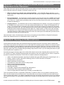
13.0 The I/O Headers
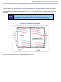
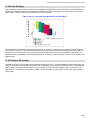
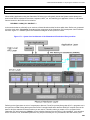
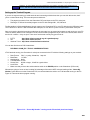
The I/O headers on the Chameleon PIC consist of a number signals that interface to both the PIC and Propeller chip. The
Propeller chip has its own 8-bit local I/O port located right under the composite video and PS/2 ports. The other headers
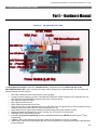
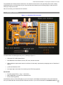
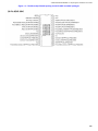
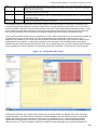
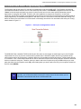
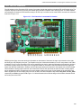
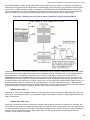
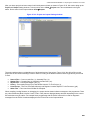
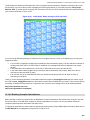
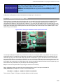
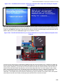
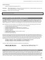
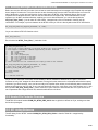
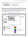
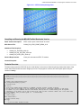
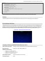
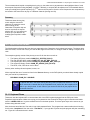
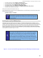
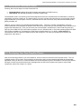
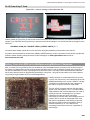
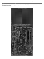
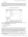
surrounding the Chameleon PCB interface mostly to the PIC chip. Let’s take a look at the PCB for a moment for reference
as shown in Figure 13.1.
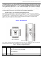
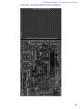
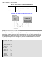
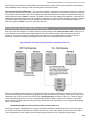
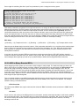
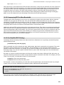
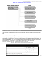
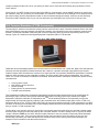
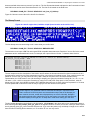
Figure 13.1 – The Chameleon’s annotated I/O headers.
Referring to the figure, there are two 8-pin I/O headers on the bottom of the board. A single 16-pin header on the right,
and finally the 8-bit Propeller local port. The Propeller local port is discussed elsewhere, so let’s concentrate on the other
3 headers. First off, on the Chameleon PIC version specifically we tried to match the Chameleon AVR (which is similar to
the Arduino) signal names to the same pins, so programs written for Chameleon AVR and Arduinos that use digital I/O
would work with little modification. Similarly, we used the same naming conventions for the signals such as Dn for digital
I/Os and AINn for analog inputs. However, the Chameleon PIC does not quite have the same number of analog inputs
and so substitutions had to be made and a few extra signals mostly on the larger 16-pin header on the right have been
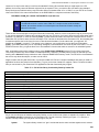
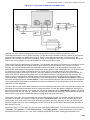
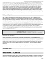
added. Signals such as the multiple power sources as well as the SPI multiplexer chip selects SPI_SS1n and SPI_SS0n
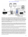
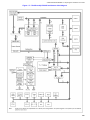
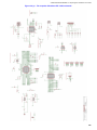
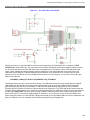
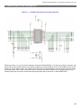
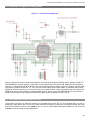
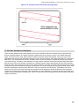
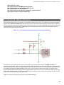
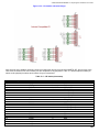
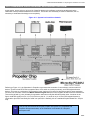
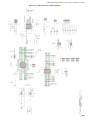
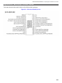
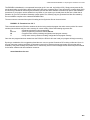
respectively and D14 and repeat of D8. Figure 13.2 below illustrates the electrical design of the headers themselves laid
out as they are on the PCB.
67