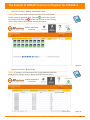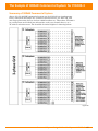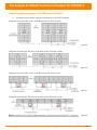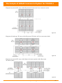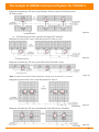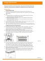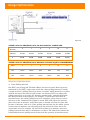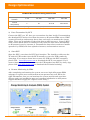
1
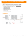
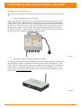
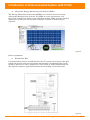
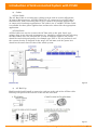
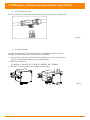
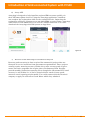
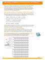
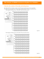
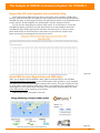
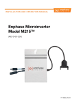
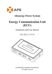
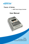
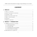
Commercial System Design Guide APsystems YC1000-3 Photovoltaic Grid-connected Microinverter Version 1.1 © All Rights Reserved TABLE OF CONTENTS Content................................................................................................................................................. 2 Introduction of Grid-connected System with YC1000-3..................................................................... 3 YC1000-3 microinverter introduction................................................................................................................... 3 System diagram.....................................................................................................................................................3 Equipments Introduction...................................................................................................................................... 4 The Sample of 300kW Commercial System for YC1000-3...................................................................9 Calculate the number of APsystems YC1000-3 Microinverters............................................................................9 Calculate the Number of APsystemsECUs............................................................................................................ 9 Calculate the number of branches and subsystems...........................................................................................10 Materials List....................................................................................................................................................... 11 Record the UID and Complete the installation Map.......................................................................................... 12 Quick EMA Account Registration and EMA Login.............................................................................................. 12 Summary of 300kW Commercial System........................................................................................................... 17 Other installation types for YC1000 microinverters........................................................................................... 18 Design Optimization...........................................................................................................................21 Design Tips.......................................................................................................................................................... 21 Voltage Rise on Wires......................................................................................................................................... 22 Monitor Optimization......................................................................................................................................... 23 The Flowchart of Commercial System Designing..............................................................................25 Commercial System Design Guide with APsystems YC1000-3 1 Content APsystems Microinverter is the world’s most technologically advanced inverter for using in utility-interactive applications. APsystems Microinverter System delivers design flexibility, integrated intelligence, increased energy harvest, and system availability not found in a central inverter-based system. NOTE: This indicates information that is important for optimized microinverter operation. Follow these instructions closely. NOTE SYMBOL Commercial System Design Guide with APsystems YC1000-3 2 Introduction of Grid-connected System with YC1000-3 YC1000-3 microinverter introduction APsystems YC1000-3 is the first three-Phase Microinverter in the world. Here is the difference below when comparing with other inverters. If you want to know more about APsystems microinverter please click www.APsystems.com First Three-Phase Microinverter in the world No Electrolytic capacitors Four modules connecting Balanced three-phase output Power line / Zigbee Individual module monitoring System diagram Figure 1 Commercial System Design Guide with APsystems YC1000-3 3 Introduction of Grid-connected System with YC500 Equipments Introduction The three key elements of an APsystems Microinverter YC1000-3 System include the: 1) APsystems Microinverter YC1000-3 APsystems YC1000-3 Microinverter is the first three-Phase Microinverter in the world. The YC1000-3 Microinverter is 95% efficient and works with 60&72&96 cells modules up to 400W. It convert the DC power from PV modules to AC power and feed the AC power into the grid. One YC1000-3 can connect 4 modules and its maximum output power is 900W and output balanced three-phase voltage. YC1000-3 use zigbee communication with ECU. It avoid interfernce of the noise in the power line comparing with PLC communication. Figure 2 2) APsystems Energy Communication Unit (ECU) The Energy Communication Unit(ECU) is a system monitoring device. The ECU uses the Zigbee signal to communicate with each YC1000-3 microinverter. The ECU connects to the Internet through a broadband router and other networking components, and uploads microinverter data to APsystems EMA server. If you want to know more about ECU, please refer to the user manual of ECU by click this address www.APsystems.com Figure 3 Commercial System Design Guide with APsystems YC1000-3 4 Introduction of Grid-connected System with YC500 3) APsystems Energy Monitoring and Analysis (EMA ) The Energy Monitoring and Analysis(EMA) is a web-based tool to manage APsystems Microinverter Systems. Use EMA to access and monitor your fleet of PV installations down to the individual module. EMA provides detailed diagnostics so that you can determine whether a system is performing as expected. Figure 4 Other equipments: 1) Distribution Box Circuit breakers must be installed before the PV system connecting to the grid, which will provide safe and convenient maintenance. Equipments like circuit breakers, meters can all be installed in a box which we called distribution box. The fig below shows a typical distribution box including circuit and panel. Figure 5 Commercial System Design Guide with APsystems YC1000-3 5 Introduction of Grid-connected System with YC500 2) Cables AC Bus Cable The AC Bus Cable is an innovative cabling system used to connect APsystems YC1000-3 Microinverters. AC BUS Cable has a T connector for each YC1000-3 microinverter, with connectors placed every 2 meters for portrait applications, or 4 meters for landscape applications. The cable’s size is 14AWG. AC Bus Cable is available for three phase applications and must be ordered for the appropriate application. AC End Cable AC End cables are used to connect the AC Bus cable to the grid. Load, type, voltage drop, power loss and temperature etc. should be considered when selecting the End cable’s wire size. Because PV system is installed outdoors, the cables should be used with good quality, for example type YJV or VV are preferred, and the current density is designed in the range of 2-4A/ mm2, and the power loss should not be more than 2% that of the whole system. Figure 6 3) AC End Cap Each branch should install an protective end cap at the end of the AC Bus cable. End Cap will prevent the water to come into the end cable. Figure 7 Commercial System Design Guide with APsystems YC1000-3 6 Introduction of Grid-connected System with YC500 4) AC T connectors Cap Cover all unused T connectors with sealing caps to protect the T connectors. Figure 8 5) AC Junction Box Install an appropriate AC Junction Box at a suitable location on the PV racking system (at the end of each branch of modules). 1. Connect the open wire end of the AC bus cable into the AC junction box using an appropriate gland or strain relief fitting. 2. Wire the conductors: L1- RED; L2 - BLACK; L3 - PINK; N - WHITE; PE – GREEN. 3. Seal the AC junction box after complete the wiring. Figure 9 Commercial System Design Guide with APsystems YC1000-3 7 Introduction of Grid-connected System with YC500 6) Array APP ArrayApp is designed to help installers register EMA accounts quickly via their iOS smart phone devices. Using the ArrayApp application, installers can complete the registration while on the construction site, Improving the registration efficiency. Customers can use their EMA account in time. ArrayApp could connect to the EMA Server via a Wi-Fi / GPRS connection. You could download the ArrayApp with IOS system on App Store. Figure 10 7) Revenue Grade Metering for Commercial Projects Revenue grade metering is often required for commercial projects that are financed or receive incentives from government organizations. These projects usually require metering accuracy within 2% to meet revenue grade requirements. Incentive programs also require that a Performance Data Provider provide monthly production reporting. Even though the APsystems ECU rated accuracy is only within 5%, it can be paired with 2% rated revenue grade meters to meet reporting requirements. You could contact with the electrical company to apply for a Revenue Grade Meter which they admitted. Commercial System Design Guide with APsystems YC1000-3 8 The Sample of 300kW Commercial System for YC1000-3 In the below chapter we will provide the detailed design steps with a 300kW commercial system by all using YC1000-3 microinverters. Follow these guidelines to make your project as trouble free as possible and we also will give some suggestions to optimize the system during design and installation period to help minimize costs, maximize performance, and ensure robust microinverter to ECU communications. Calculate the number of APsystems YC1000-3 Microinverters The desired system size for this example is 300kW STC. We decide to use 60 cells PV module and the STC output power is 260W. So we can calculate the Total number of PV modules required in this system is: 300kW 260 W / PCS 1153 .8PCS 1154 PCS The required number of YC1000-3 microinverters: 1154 PCS 4 288.5PCS 289PCS The AC output power of this system is: 288.5PCS 900 W 259.6kW So this 300kW rating commercial system needs 1154pcs PV modules with the STC output power 260W and 289 APS YC1000-3 micro-inverters, the real output power of this system would be 259.6KW. Calculate the Number of APsystemsECUs Usually a commercial system is composed of several subsystems, and the microinverters in each subsystem are monitor by one ECU. Recently one Zigbee ECU can pick up 100 YC1000-3s. So we just need 3 Zigbee ECUs. NOTE: The Zigbee ECU is not forced to put into the distribution box. You only need put the Zigbee ECU close to the PV system to let the YC1000-3 could talk with ECU by strong zigbee signal. Figure 11 Commercial System Design Guide with APsystems YC1000-3 9 The Sample of 300kW Commercial System for YC1000-3 Calculate the number of branches and subsystems The Zigbee ECU could pick up about 100 YC1000-3 microinverters. So we split 289 YC1000-3 microinverters into 3 subsystems with 99+99+91 YC1000-3 microinverters. The diagram of Subsystem 1 with 99 YC1000-3 microinverters Figure 12 The diagram of Subsystem 2 with 99 YC1000-3 microinverters Figure 13 Commercial System Design Guide with APsystems YC1000-3 10 The Sample of 300kW Commercial System for YC1000-3 Materials List The table below is the components list for this system: Type Quantity Specification Function 260W PV module 1154 pcs Produce DC power APsystems YC1000-3 microinverter 389 pcs Convert the DC power to AC power Distribution box 3 pcs Use to install circuit breakers and meter etc 3 pcs (Zigbee communication with YC1000-3) Receive data from YC1000-3 microinverters and upload the data to EMA server 27 pcs (2 meters between each connector) Transmit AC power to grid End Cable 27 pcs (choose proper length and cable size) Connect the last inverter to the junction box with end cable Junction box 27 pcs Where connect end cable to grid Protective end cap 27 pcs Seal the AC bus cable at the end of each branch 3-phase circuit breaker 31 pcs (26 breakers with 15Ax3, 1 breaker with 4Ax3, 6 breakers with 160Ax3) Protect the photovoltaic system Surge protection device 3 pcs Protection of Outdoor lighting Meter 3 pcs Use to calculate the correct output power ECU-3Z AC Bus Cable Commercial System Design Guide with APsystems YC1000-3 11 The Sample of 300kW Commercial System for YC1000-3 Record the UID and Complete the installation Map Each APsystems Microinverter has a removable serial number (UID) label located. Peel the label off, and affix it to the respective location on the APsystems installation map, so this map will show the physical location of each Microinverter in the system. It will simplify the maintenance for the system in future. If you use the ArrayApp to register this sytem. It is still best to create the installation maps, and then scan the microinverter serial numbers from the installation map. When placing the stickers onto the map, it is best to place them with about an inch between each sticker to prevent the scanner tool from erroneously scanning the incorrect bar codes. Figure 14 Quick EMA Account Registration and EMA Login After you complete the installation map, please send the map to the mailbox [email protected] or you could register this system by your installer account. If you use the ArrayApp to resister the system. You just submit the info on your phone with internet connection. After you complete the registration, you could login in your system with entering your username and password by click www.APsystems.com to login in your system. EMA Login Page - Insataller Account Figure 15 Commercial System Design Guide with APsystems YC1000-3 12 The Sample of 300kW Commercial System for YC1000-3 Installer Portal - Customer List Page Figure 16 Installer Portal - Module Power page Figure 17 Commercial System Design Guide with APsystems YC1000-3 13 The Sample of 300kW Commercial System for YC1000-3 Installer Portal -DC Performace Graph page Figure 18 Installer Portal - AC Performace Graph page Figure 19 Commercial System Design Guide with APsystems YC1000-3 14 The Sample of 300kW Commercial System for YC1000-3 Installer Portal - Registraion page Figure 20 End User Portal - DashBoard Page NOTE: End user account could not see the detailed AC and DC performace graph data. End user could downlod the chart by many formats. ENERGY MONITORING & ANALYSIS Figure 21 Commercial System Design Guide with APsystems YC1000-3 15 The Sample of 300kW Commercial System for YC1000-3 End User Portal - Module Performance Page NOTE: The system status on the top right coner will display if this system is running well. The sign means the system is running well. The sign means the system is not running well. Please contact APsystems technical support. ENERGY MONITORING & ANALYSIS Figure 22 End User Portal - Report Page NOTE: Customer could download the Yearly/Monthly/Weekly/ Daily history energy data by Excel or PDF from this page. ENERGY MONITORING & ANALYSIS Figure 23 Commercial System Design Guide with APsystems YC1000-3 16 The Sample of 300kW Commercial System for YC1000-3 Summary of 300kW Commercial System Above all, this 300kW commercial system can be divided into 3 subsystems. Every subsystem has 99(or 91) YC1000-3 microivnerters, one ECU-3Z, and one surge protection devices and two 160A breakers etc. Then these YC1000-3 in a subsystem are divided into 9 branches, and every branch has 11 or 3 YC1000-3 microinverters. The detailed electrical digram is showing below: Figure 24 Commercial System Design Guide with APsystems YC1000-3 17 The Sample of 300kW Commercial System for YC1000-3 Other installation types for YC1000 microinverters 1) YC1000 microinverters operate with 60cell or 72cell PV modules Diagram of portrait PV array with APsystems YC1000-3 (2x2) Figure 25 Diagram of landscape PV array with APsystems YC1000-3 (2x2) Figure 26 Diagram of portrait PV array with APsystems YC1000-3 (1x4) Figure 27 Diagram of landscape PV array with APsystems YC1000-3 (1x4) Figure 28 Commercial System Design Guide with APsystems YC1000-3 18 The Sample of 300kW Commercial System for YC1000-3 Diagram of portrait PV array with APsystems YC1000-3 AC bus connection (2x2) Figure 29 Diagram of landscape PV array with APsystems YC1000-3 AC bus connection (2x2) Figure 30 Diagram of portrait PV array with distance between panels with APsystems YC1000-3 (2x2) Figure 31 Commercial System Design Guide with APsystems YC1000-3 19 The Sample of 300kW Commercial System for YC1000-3 Diagram of landscape PV array with distance between panels with APsystems YC1000-3 (2x2) Figure 32 2) YC1000 microinverters operate with 96cell PV modules. Diagram of portrait PV array with APsystems YC1000-3 (1x3) Figure 33 Diagram of landscape PV array with APsystems YC1000-3 (1x3) Figure 34 Diagram of portrait PV array with APsystems YC1000-3 Figure 35 Diagram of landscape PV array horizontally with APsystems YC1000-3 Figure 36 Commercial System Design Guide with APsystems YC1000-3 20 Design Optimization Through optimization of the design below, the system will perform better and it will also reduce the cost of construction and maintenance. We provide some suggestions and methods for installers to optimize the system in this chapter. Design Tips Panel installation tips. 1) 2) 3) 4) Azimuth:You’d better keep the panel facing north if the system is in the Southern Hemisphere, or facing south if the system is in the Nothern Hemisphere. Tilt A. Normally the best installation tilt is the latitude where the system located in when the latitude is from 0-25. B. When the latitude is from 26-40. The best installation tilt is equal to the latitude plus 5 to 10. C. When the latitude is from 41-55. The best installation tilt is equal to the latitude plus 10 to 15. Panel model:Keep the four panels which connect to one YC1000-3 in same model, in order to provide balanced DC power input. The best installation type for panels is landscape. There is no need to use DC extenction cables which will reduce power loss on cables(See Figure 25). YC1000-3 microinverter installation tips. 1) 2) Install the APS YC1000-3 Microinverter under the module, out of rain and sun. Do not mount the microinverter in a position that allows long-term exposure to direct sunlight or in a vertical orientation that allows water to collect in the DC connector recess. Ensure that all AC and DC wiring is correct. Ensure that none of the AC and DC wires are pinched or damaged. Ensure that all AC isolators are properly closed. You will hear “click” which means the AC cable connection is ok. Figure 37 3) 4) 5) Choose proper cable size when connecting the inverter to the grid with end cable if the PV system is far connecting point of grid. The power loss should not be more than 2% that of the whole system. Please see refer to the detailed introduction below.(4.2 Voltage Rise on wires) Allow a minimum of 10 centimeters(cm) between the top of the roof and the bottom of the microinverter Make sure the inverter’s antenna point to the ground vertically which will strengthen the Zibee communication between ECU and YC1000-3s. Especially for the situation that the panel is very close to the roof. Figure 38 Commercial System Design Guide with APsystems YC1000-3 21 Design Optimization 6) Cover all unused T connectors with sealing caps to protect the T connectors. Figure 39 ECU installation tips 1) 2) Put the ECU into the distribution box or somewhere close to the PV system, in order to bulid strong zigbee signal for the communication with ECU and YC1000-3s. And put the antenna out of the distribution box and keep the ECU’s antenna parallel with the YC1000-3s antenna, this also will bulid good communcation between ECU and inverters. Provide an outbound port and an Ethernet connection for each ECU. Install an always-on connection to the Internet. When the Internet connection is not on,the ECU stores data. Then, when the internet connection returns, the ECU sends stored data while simultaneously collecting and processing large amounts of live data. This delays data collection and transmission, and impedes the display of the most recent data in EMA. EMA registration tips. 1) 2) Don’t forget peel the serial number labels from the YC1000-3 microinverters and placing the labels on the installation map. You then use this map to build a virtual array in EMA. List all YC1000-3 microinverter serial numbers and their correct placement within the array. List the tilt and azimuth of the array relative to the placement of the serial number labels. Voltage Rise on Wires Voltage rise must be considered when designing a photovoltaic system. Over voltage rise will consume more power, but also may trig protection function because of misjudging the grid voltage, so we advise that the total voltage rise should not be more than 2% on a single branch. The table below gives the calculation results of the voltage rise on each microinverter of a branch with YC1000-3 operating at full load. If you want to know more the how to calculate the rise on wires for YC1000-3 microinverters, please click www.APsystems.com Commercial System Design Guide with APsystems YC1000-3 22 Design Optimization Figure 40 YC1000-3 Vrise for 480V/60Hz,5 wire, 2m Portrait AC Bus 14 AWG cable. YC1000-3 Quantity 6 7 8 9 10 11 VRise(V) 0.1104 0.1325 0.1546 0.1767 0.1988 0.2209 % 0.027% 0.033% 0.038% 0.044% 0.049% 0.055% YC1000-3 Vrise for 480V/60Hz,5wire, Maximum end cable length for 12AWG&14AWG AWG 6 7 8 9 10 11 #14 123m 105m 92m 82m 73m 67m #12 153m 131m 115m 103m 92m 83m Monitor Optimization 1) Data Polling Interval One ECU can pick up 200 YC1000-3 Micro-inverters at most. More inverters monitored by one ECU, longer time needs for a data polling interval. Usually, a single inverter’s polling interval is about 5 seconds, which means for a system with 50 inverters, the interval will become 4-5 minutes. ECU can adjust the polling interval by a step size of 5 minutes automatically, and that will make the data provided seem regularly, for example, a system with less than 50 microinverters, the whole polling interval is 5 minutes, when there are more inverters or the communication signal is weak, ECU will adjust the interval time to become 10 minutes, and if more time is needed, the interval time will become 15 minutes, and so on. If the polling interval time for the whole system is more than 20 minutes, the adjusting step size will not be fixed, but is the actual time cost. For example, the last interval time is 22 minutes, but next polling’s interval time may be 26 minutes or others. The table below shows the relationship between polling interval time and the quantity of microinverters: Commercial System Design Guide with APsystems YC1000-3 23 Design Optimization YC1000-3 Microinverter Polling Interval Time Quantity of Inverters 1~50 50~100 100~150 150~200 Interval Time(minute) 5 10 15 or 20 20 or above Note: The polling interval time may vary with the field’s condition. 2) Data Transmitted by ECU Connect the ECU to a PC, then you can monitor the data locally. If transmitting the datathat ECU had received from inverters to APsystems EMA server, EMA system will analyze and manage these data, and users can monitor the system online. There are 2 methods to upload the data to APS servers: 1. Connect ECU with a router (Both wired or wireless are ok), then the data will be transmitted to APsystems server by internet; 2. Transmit the data to base stations of mobile operators’ by GPRS, and then upload to internet, and transmit to servers. 3) Start ECU Start the ECU, enter into the ECU local interface. The installer could enter the YC1000-3’s UID number into the ECU muanlly or enter the UID number by ArrayApp. If you want to know how to enter the UID into the ECU manaully, please click www.APsystems.com to download the ECU user manual. If you want to know more about how to enteer the UID number into ECU by Array App, please click www.APsystems.com to download the Technical training. 4) Remote Monitoring by EMA After completing and starting the system, users can login APsystems EMA webpage to register an account(website:www.apsema.com), and Fill in the right information, then you can monitor the system anytime and anywhere. (Please send your installation map and customer information to APsystems support mailbox to apply for a login account firstly.) Figure 41 Commercial System Design Guide with APsystems YC1000-3 24 The Flowchart of Commercial System Designing Figure 42 Commercial System Design Guide with APsystems YC1000-3 25 Contact Information ALTENERGY POWER SYSTEM Inc. Web: www.APsystems.com APsystems Jiaxing China No. 1, Yatai Road, Nanhu District, Jiaxing, Zhejiang Tel: +86 573 8398 6967 Mail: [email protected] APsystems Shanghai China B403 No. 188, Zhangyang Road, Pudong, Shanghai Tel: +86 021 3392 8205 Mail: [email protected] APsystems Australia Suite 502, 8 Help Street, Chatswood NSW 2067 Australia Tel: +61 (0)2 8034 6587 Mail: [email protected] APsystems America 600 Ericksen Ave NE, Suite 200 Seattle, WA 98110 Tel: 844-666-7035 Mail: [email protected] APsystems Europe Cypresbaan 7,2908LT,Capelle aan den Ijssel, The Netherlands Tel: +0031-10-2582670 Mail: [email protected] Commercial System Design Guide with APsystems YC1000-3 26