1
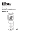
DTR.APREGN.01(ENG) APLISENS MANUFACTURE OF PRESSURE TRANSMITTERS AND CONTROL INSTRUMENTS USER’S MANUAL SMART DIFFERENTIAL PRESSURE TRANSMITTER type: APRE-2000GN Edition A WARSAW OCTOBER 2013 APLISENS S.A. 03-192 Warszawa, ul. Morelowa 7 tel. +48 22 814 07 77; fax +48 22 814 07 78 www.aplisens.pl, e-mail: [email protected] A 1 DTR.APREGN.01(ENG) Symbols used Symbol i Description Warning to proceed strictly in accordance with the information contained in the documentation in order to ensure the safety and full functionality of the device. Information particularly useful during installation and operation of the device. Information on disposal of used equipment BASIC REQUIREMENTS AND SAFE USE - The manufacturer will not be liable for damage resulting from incorrect installation, - - - - failure to maintain the device in a suitable technical condition, or use of the device other than for its intended purpose. Installation should be carried out by qualified staff having the required authorizations to install electrical and pressure-measuring devices. The installer is responsible for performing the installation in accordance with these instructions and with the electromagnetic compatibility and safety regulations and standards applicable to the type of installation. The device should be configured appropriately for the purpose for which it is to be used. Incorrect configuration may cause erroneous functioning, leading to damage to the device or an accident. In systems with pressure transmitters there exists, in case of leakage, a danger to staff on the side where the medium is under pressure. All safety and protection requirements must be observed during installation, operation and inspections. If a device is not functioning correctly, disconnect it and send it for repair to the manufacturer or to a firm authorized by the manufacturer. In order to minimize the risk of malfunction and associated risks to staff, the device is not to be installed or used in particularly unfavourable conditions, where the following dangers occur: - possibility of mechanical impacts, excessive shocks and vibration; - excessive temperature fluctuation, exposure to direct sunlight; - condensation of water vapour, dust, icing. Changes in the production of transmitters may precede a paper updating for the user. The current user manuals are available at http. www.aplisens.pl A 2 DTR.APREGN.01(ENG) 1. 2. 3. 4. 5. INTRODUCTION .................................................................................................................................... 3 TRANSMITTER DOCUMENTATION ...................................................................................................... 3 APPLICATIONS AND MAIN FEATURES............................................................................................... 3 IDENTIFYING MARKS. ORDERING PROCEDURE ............................................................................... 3 TECHNICAL DATA ................................................................................................................................ 3 5.1. ELECTRICAL PARAMETERS .......................................................................................................................................... 3 5.2. PERMITTED ENVIRONMENTAL CONDITIONS .................................................................................................................... 4 5.3. RATING OF CASE PROTECTION IP65 ACCORDING TO PN-EN 60529:2003 .................................................................... 4 5.4. MEASUREMENT RANGES AND METROLOGICAL PARAMETERS. ......................................................................................... 4 5.5. CONSTRUCTION MATERIALS ........................................................................................................................................ 4 6. MEASUREMENT PRINCIPLES AND CONSTRUCTION ............................................................................. 4 7. 6.1. MEASUREMENT PRINCIPLES, ELECTRONIC SYSTEM. ..................................................................................................... 4 6.2. CONSTRUCTION. ........................................................................................................................................................ 5 PLACE OF INSTALLATION .................................................................................................................. 5 7.1. GENERAL RECOMMENDATIONS .................................................................................................................................... 5 7.2. LOW AMBIENT TEMPERATURE. .................................................................................................................................... 5 7.3. MECHANICAL VIBRATION, CORROSIVE MEDIA. .............................................................................................................. 5 8. 9. INSTALLATION AND MECHANICAL CONNECTIONS.......................................................................... 5 8.1. INSTALLATION AND CONNECTIONS ................................................................................................................................ 5 ELECTRICAL CONNECTION ................................................................................................................ 6 9.1. GENERAL RECOMMENDATIONS .................................................................................................................................... 6 9.2. ELECTRICAL CONNECTIONS ......................................................................................................................................... 6 9.3. PROTECTION FROM EXCESS VOLTAGE .......................................................................................................................... 6 10. SETTING AND REGULATION ............................................................................................................... 6 10.1. TRANSMITTER RANGE. BASIC RANGE. DEFINITIONS .................................................................................................... 6 10.2. CONFIGURATION AND CALIBRATION ........................................................................................................................... 6 11. INSPECTIONS AND SPARE PARTS. ...................................................................................................14 11.1. PERIODIC INSPECTIONS........................................................................................................................................... 14 11.2. UNSCHEDULED INSPECTIONS................................................................................................................................... 14 11.3. OVERLOADING DAMAGE .......................................................................................................................................... 14 12. 13. 14. 15. 16. PACKING, STORAGE AND TRANSPORT ...........................................................................................14 GUARANTEE .......................................................................................................................................14 ADDITIONAL INFORMATION...............................................................................................................14 RELATED DOCUMENTS ......................................................................................................................14 FIGURES ..............................................................................................................................................15 FIG. 1. APRE-2000GN – BLOCK DIAGRAM. ...................................................................................................................... 15 FIG. 2. APRE-2000GN - ELECTRICAL CONNECTIONS. ....................................................................................................... 15 FIG. 3. APRE-2000GN - BACK LIGHTING JUMPER VIEW ON TRANSMITTER ELECTRIC BOARD................................................. 16 FIG. 4. APRE-2000GN SMART PRESSURE TRANSMITTER – DIMENSIONS, CONNECTIONS, FIXINGS. ....................................... 17 A 3 1. DTR.APREGN.01(ENG) INTRODUCTION 1.1. This Manual is intended for users of APRE-2000GN smart differential pressure transmitters, containing the data and guidelines necessary to understand the transmitters functioning and how to operate them. It includes essential recommendations concerning installation and use, as well as emergency procedures. 1.2. The transmitters comply with the requirements of EU directives as shown on the plate and with the relevant Declaration of Conformity. 2. TRANSMITTER DOCUMENTATION Transmitters are delivered in single and/or multiple packs. Together with the transmitter are delivered: a) Product certificate, which is also as the warranty card; b) Declaration of conformity - on request; c) User’s Manual numbered: DTR.APREGN.01(ENG). Items b), c) are available at: www.aplisens.pl 3. APPLICATIONS AND MAIN FEATURES 3.1. The APRE-2000GN smart low differential pressure transmitters are designed to measure differential pressure, gauge pressure, vacuum and under pressure of gases. Typical applications include the measurement of blast pressure, chimney draughts etc. 3.2. The APRE-2000GN transmitters generate a 4...20mA output signal and a digital communication signal (HART) in a two-wire system (current loop). The use of smart electronics enables regulation of the zero point, the measurement range, damping, radical conversion characteristic and other functions using an Aplisens KAP-03 communicator or a PC with a HART/RS232 converter and Aplisens “Raport 2” configuration software. 4. IDENTIFYING MARKS. ORDERING PROCEDURE 4.1. Every transmitter carries a rating plate containing at least the following information: CE mark, manufacturer name, transmitter type, serial number, pressure range, static pressure limit, output signal, power supply voltage. Version types and the method of specifying the desired product are described in the current “Information Cards” and in the Catalogue. 5. TECHNICAL DATA 5.1. Electrical parameters Power supply Output signal Communication 12* ÷ 36V DC 4 ÷ 20mA realised via a 4÷20mA signal using KAP-03 communicator or PC and RS/Hart converter with Raport 2 software Resistance for communication 250 ÷ 1100Ω, min 240Ω Usup[V]-12V* Load resistance RLmax[Ω] = 0,0225A *) 15 V DC for transmitters with display backlight. i - Usuply min. = 12+ 0,0225xRL [V] for transmitters without display backlight. - Usuply min. = 15+ 0,0225xRL [V] for transmitters with display backlight. Output updating time Additional electronic damping Voltage for insulation testing Excess voltage protection 500ms 0...30s 75V AC or 110V DC. see p.9.3. A 4 DTR.APREGN.01(ENG) 5.2. Permitted environmental conditions -30ºC ÷ 80ºC for polycarbonate (PC) casing -30ºC ÷ 60ºC for ABS casing as above -10ºC 70ºC 0 ÷ 90% not recommended not recommended Operating temperature range Medium temperature range Thermal compensation range Relative humidity Vibration during operation Exposure to direct sunlight 5.3. Rating of Case Protection IP65 according to PN-EN 60529:2003 5.4. Measurement ranges and metrological parameters. 5.4.1. Measurement ranges N Nominal range (FSO) Minimum set range 1 2 3 4 5 0...25mbar (0...2500Pa) -2.5...2.5mbar (-250...250Pa) -7...7mbar (-700...700Pa) -25...25mbar (-2500...2500Pa) -100…100mbar (-10...10kPa) 1mbar (100Pa) 0.2mbar (20Pa) 1mbar (100Pa) 5mbar (500Pa) 20mbar (2kPa) Overpressure limit Static pressure limit 1bar 350mbar 350mbar 1bar 1bar 350mbar 350mbar 350mbar 1bar 1bar 5.4.2. Metrological parameters. Nominal range Accuracy 0...25mbar 0.075 % Thermal error -2.5...2.5mbar 0.25 % -7...7mbar -25...25mbar -100…100mbar 0.1 % 0.1 % 0.075 % 0.1 % (FSO)/ 10ºC, max 0.4 % (FSO) for the whole thermal compensation range 5.5. Construction materials 5.5.1. Casing: PC B65T – polycarbonate; ABS B65T. 5.5.2. Pressure Connectors The pressure connectors are adapted to ø 6x1 plastic tubes (standard) and/or M20x1.5/6x1 adapter (brass) as peripherals. 6. MEASUREMENT PRINCIPLES AND CONSTRUCTION 6.1. Measurement Principles, Electronic System. Differential pressure transmitters work by converting changes in the resistance of a ceramic sensor, which are proportional to the measured differential pressure, into a standard current signal. The active sensing element is a ceramic sensor. A transmitter block diagram is presented in Figure 1. At the circuit input two analogue signals are provide: the measured pressure reflecting and the sensing module temperature. These signals are digitalized and provide to a microprocessor input which controls the transmitter’s operation. Using input data during the production process adjusts for thermal errors and carries out linearization. After digital processing, the signal is converted into an analogue 4÷20mA current signal again, with a superimposed Hart signal. For communication with the transmitter via the signal line an Aplisens KAP communicator, or a computer meeting the requirements given in 10.2.4, are used. The transmitter’s output is fitted with a radio-noise filter and other elements protecting against EM. A 5 DTR.APREGN.01(ENG) 6.2. Construction. The basic units of transmitter are: casing, pressure sensor, processing unit with local LCD display, as well as anti-noise filter. 6.2.1. Casing The casing of APRE-2000GN transmitter is made with polycarbonate (PC) or with akrylonitrylo-butadieno-styren (ABS) and it consists with the case as well as the transparent cover. 6.2.2. Processing unit 6.2.2.1. The processing module consists from the main plate of electronics with LCD display, as well as the plate of A/C converter. 6.2.2.2. The ceramic pressure sensor is closed in the plastic case equipped in the pressure connections as well as the electrical exit terminals. 7. PLACE OF INSTALLATION 7.1. General recommendations 7.1.1. The transmitters can be installed both indoors and outdoors. It is recommended that transmitters intended for outdoor use be placed in a box or under cover. 7.1.2. The place of installation should be chosen in a such way as to allow a good access to the device and to protect its from mechanical damage. In planning the installation of the transmitter and configuration of the impulse lines, attention should be paid to the following requirements: i The impulse lines should be as short as possible, with a sufficiently large cross-section, and free of sharp bends, in order to prevent blockages; The transmitters should be installed above the measuring point, so that condensation flows down towards the site of the pressure measurement. The impulse lines should be inclined at a gradient of at least 10cm/m; The configuration of the impulse lines and the valve connection system should be chosen with regard to the measurement conditions and to requirements such as the need to reset the transmitters in position and the need for access to the impulse lines. 7.1.3. Should also be paid attention to possible installation faults which may lead to measurement errors, such as connections which are not tight, sediment blockage in lines which are too narrow, liquid column in a gas line etc. 7.2. Low Ambient Temperature. Thermal insulation can protect the transmitter casing and lines only from brief exposure to low temperatures. 7.3. Mechanical Vibration, Corrosive Media. 7.3.1. The transmitter should be installed in a place which is free of vibrations. If vibrations are carried to the transmitter via the impulse lines, use should be made of elastic lines. 7.3.2. Avoid the installing of transmitters in the places of appearance the heavy objects hitting. 8. INSTALLATION AND MECHANICAL CONNECTIONS 8.1. Installation and connections 8.1.1. The APRE-2000GN transmitter can be mounted on a wall or on a control panel. The transmitter is fitted with connectors which fit to an Ø6x1 elastic impulse tube. When the measuring impulse is transmitted via a metal terminal with M20x1.5 connector, an adapter is used between the M20x1.5 thread and the Ø6x1 terminal. Transmitters should be installed in a vertical position. The way of impulse line leading should enable the vapour flowing towards the place of instalation (pipeline). Where there is a significant difference between the height at which the transmitter is mounted and the height of the impulse source, particularly if the measurement range is small, the reading may fluctuate depending on the temperature difference between the impulse lines. This effect can be reduced by ensuring that the impulse lines run side by side. To equipment completing in assembling of transmitters, will be helpful the information about connecting pressure elements such as: reductive, nests, valves, reductive yokes, signal tubes. Data on this subject are contained in APLISENS catalogue. A 6 9. DTR.APREGN.01(ENG) ELECTRICAL CONNECTION 9.1. General recommendations 9.1.1. It is recommended that twisted pair cabling be used for the signal lines. If the transmitter and signal line are subject to a large amount of electromagnetic interference, then shield pair cable should be used. The signal lines should not run alongside network power supply cables or near to large electrically-powered devices. The devices used together with the transmitters should be resistant to electromagnetic interference from the transmission line in accordance with compatibility requirements. i 9.1.2. Wet or rising damp inside transmitter can cause its damage. When the cables isolation in the packing gland is ineffective (for example, when single wire cables are used) the opening of the gland should be carefully sealed with an elastic sealing compound to obtain IP65 protection. It is useful to form the segment of the signal wire leading to the packing gland into a protective loop to prevent condensation from running down in the direction of the gland. 9.2. Electrical connections i The APRE-2000GN transmitters are to be connected as shown in fig. 2. 9.3. Protection from excess voltage 9.3.1. Transmitters can be in danger from excess voltage caused by connection faults or atmospheric electrical discharge. Protection from excess voltage between transmission line cables is provided by TVS diodes assembled in anti-noise filter. For long lines is profitably apply a protective device external for example one protection near transmitter (or inside the transmitter), and second near entries to co-operating devices. 10. SETTING AND REGULATION APRE-2000GN transmitters are factory calibrated to the range stated in the order or to the basic range. After installation, the transmitter’s zero-point may move and require adjustment. This applies particularly where the measurement range is small. 10.1. Transmitter Range. Basic Range. Definitions 10.1.1. The maximum range of pressure, or differential pressure, which the transmitter can measure is called the “basic range” (for specifications of basic ranges see section 5.4.1). The width of the basic range is the difference between the upper and lower limits of the basic range. The internal characteristic conversion curve for the basic range is coded in the transmitter’s memory. This is the reference curve used when making any adjustments which affect the transmitter’s output signal. 10.1.2. When the transmitter is in use the term “set range” is used. The set range is the range whose lower end-point corresponds to an output current of 4mA and whose upper end-point corresponds to a current of 20mA (or 20mA and 4mA respectively when the conversion curve is inverted). The set range may cover the whole of the basic range or only a part of it. The width of the set range is the difference between its upper and lower end-points. The transmitter may be set to any range within the basic range of pressure values, subject to the restrictions set out in the table in section 5.4.1. 10.2. Configuration and Calibration 10.2.1. The transmitter has features which enable metrological and identification parameters to be set and altered. The configurable metrological parameters affecting the transmitter’s output current include the following: a) Unit in which the measured pressure is expressed on the display; b) Upper end-point of the set range; c) Lower end-point of the set range; d) Time constant; e) Type of characteristic curve: linear or radical. A 7 DTR.APREGN.01(ENG) Parameters of an informational nature which cannot be altered include the following: f) Upper limit of the basic range; g) Lower limit of the basic range; h) Minimum range. 10.2.2. Other identification parameters, not affecting the output signal, include: device address, device type code, factory identification code, factory device code, number of preambles (3÷20), UCS, TSD, program version, electronics version, flags, serial number, label tag, description tag, date tag, message, record number, sensing module number. The process of setting the parameters listed in 10.2.1 and 10.2.2 is called “Configuration”. 10.2.3. It is possible to carry out a “pressure zeroing” procedure, for example to compensate for measurement deviation caused by a change in position during the transmitter installation. The transmitter may also be calibrated, by taking readings with the input pressure controlled using a standard device. These process and zero-point adjustments are called “Calibration”. 10.2.4. Configuration and Calibration of the transmitter are carried out using an Aplisens KAP communicator, certain Hart communicators or a PC with Hart/RS232 converter and Aplisens Raport 2 software. Together with the “RAPORT 2” configuration software there is an „INTERVAL LINEARIZATION” software supplied to enable the input of 21-point nonlinear functional characteristics to the transmitter. A description of the functions of the KAP communicator is contained in the KAP Communicator Operating Manual, and information on the Hart/RS232 converter can be found on the Hart/RS232/01 Converter information sheet. 10.2.5. Local configuration of transmitters If the option of local configuration is active, operator can change transmitter set using buttons being below display. The access to buttons will get after unscrewing the side cover. Then we can also change the display position turning it with 90º angle position (see fig. 4). If the option of local configuration is active, operator can change transmitter set using buttons being below display. To enter at the local set change of the work mode, you should press one button and hold its about 4s. If using buttons can't change the transmitter configuration, the local transmitter configuration is switched of and to its switching on is necessary to use the KAP 3 Calibrator. The buttons are signed with symbols: [↑] [↓] [◙] After pressing by 4 seconds any of buttons there will appear on display “EXIT”. If we will confirm this announcement across pressing and holding button [◙] by 1 sec, we will go out from the local change of the MENU set. If we will not confirm, we can move in MENU and change interesting us parameters. The time of pressing [↑] [↓] [◙] has to be longer than 1s. Pressing button [↑] moves up in tree's structure MENU Pressing button [↓] moves down in tree's structure MENU Pressing [◙]confirms choice and leads change. Local menu | EXIT | | PV ZERO_________ | | | | | | | | | (First announcement which will see after inclusion of Menu Local. If you will confirm this option, you will go out from Local Menu and you will come back to continue of measuring) \ BACK | | | PV ZERO (Return to Local Menu. If you will confirm this option, you will come back to main tree of Local Menu) (Pressure zeroing. If you will confirm this option, transmitter will confirm the party of command by the "DONE" announcement or the proper number of error will notify.) A 8 SET LRV_________ | \ | BACK | | | | | BY PRESsure | | | | | | | BY VALUE | | | | | | | | | | SET URV___ | | | | | | | | | | | | | | | | | | | | | DTR.APREGN.01(ENG) (The Setting of the range of the set LRV beginning) (Return to Local Menu. If you will confirm this option, you will come back to main tree of Local Menu) (Setting LRV across setting pressure. If you will confirm this option, transmitter will confirm the party of command by the "DONE" announcement or the proper number of error will notify) (Setting the LRV across inscribing of value.) (After confirmation will display current LRV value before the passage in mode of edition) ↓ ↓ +/(Choose and confirm sign introduced parameter) ↓ 00000 (Introduce in sequence , digit after digit, 5 digital number with point or without point. After confirmation the last 5 digit of the parameter transmitter will confirm the party of command by the "DONE" announcement or the proper number of error will notify. The parameter will be written down in units "UNIT") (The setting of the end of the set URV range) \ BACK (Return to Local Menu. If you will confirm this option, | you will come back to main tree of Local Menu) | BY PRESsure (Setting URV across setting pressure. If you will confirm this | option, transmitter will confirm the party of command by the | "DONE" announcement or the proper number of error will notify | BY VALUe (Setting the URV across inscribing of value) \ (After confirmation will display current URV value before the passage in mode of edition) ↓ ↓ +/(Choose and confirm sign introduced parameter) ↓ 00000 (Introduce in sequence, digit after digit, 5 digital number with point or without point. After confirmation the last 5 digit of the parameter transmitter will confirm the party of command by the "DONE" announcement or the proper number of error will notify. The parameter will be written down in units "UNIT") A UNIT______ | | | | | | | | | | | | | | | | | | | | | | | | | || 9 \ BACK | | | | | IN_H2O IN_HG FT_H2O MM_H2O MM_HG PSI BAR MBAR G/SQCM KG/SQCM PA KPA TORR ATM M_H2O MPA INH20@4 MMH2O@4 |DAMPING________ | \ | BACK | | | | | | | | | | | | 0 [S] | 2 [S] | 5 [S] | 10 [S] | 30 [S] | 60 [S] | | TRANSFEr_______ | \ | BACK | | | | | | | | | | | | | LINEAR | SQRT | SPECIAL | SQUARE | | DTR.APREGN.01(ENG) (Return to Local Menu. If you will confirm this option, you will come back to main tree of Local Menu) (Confirm one of the following characteristics across longer press button ◙. After parameter confirmation transmitter will confirm the party of command by the "DONE") (Setting of the solid temporary suppression of the process variable) (Return to Local Menu. If you will confirm this option, you will come back to main tree of Local Menu) (Confirm one of the following values time constant across longer press button ◙. After parameter confirmation transmitter will confirm the party of command by the "DONE") (Setting of the current output form) (Return to Local Menu. If you will confirm this option, you will come back to main tree of Local Menu) (Confirm one of the following characteristics across longer press button ◙. After parameter confirmation transmitter will confirm the party of command by the "DONE") (Linear) (square root) (user’s ) (square) A % SQRT______ | \ | | | | | | | | | | | | | LCD1 VARiable__ | | | | | | | | | | | | | | | LCD2 VARiable | | | | | | | | | | | | | | | | | | | | 10 DTR.APREGN.01(ENG) (square root characteristic cut-of point setting) BACK | | | | | | 0 % 1 % 2 % 3 % 4 % 5 % (Return to Local Menu. If you will confirm this option, you will come back to main tree of Local Menu) (Confirm one of the following percent value across longer press button ◙. After parameter confirmation transmitter will confirm the party of command by the "DONE") (Type of the process variable displayed on LCD1) \ BACK | | | | | | CURRENT | | PERCENT (Return to Local Menu. If you will confirm this option, you will come back to main tree of Local Menu) (Confirm one of the following option across longer press button ◙. After parameter confirmation transmitter will confirm the party of command by the "DONE") (On LCD1 will displayed current value in current loop) (The percent value output signal will displayed on LCD1) (Type of the process variable displayed on LCD2) \ BACK | | | | | | | PRESSURE | USER | | UNIT | | NO UNIT (Return to Local Menu. If you will confirm this option, you will come back to main tree of Local Menu) (Confirm one of the following option across longer press button ◙. After parameter confirmation transmitter will confirm the party of command by the "DONE") (The pressure value will displayed on LCD2) (The user’s units will displayed on LCD2) (The current unit or user’s unit alternately with process variable will displayed on LCD2) (The current unit or user’s unit alternately with process variable will not displayed on LCD2) A 11 DTR.APREGN.01(ENG) LCD2 DP_________ | \ | BACK | | | | | | | | | | | | | XXXXX | | | XXXXX | | | XXXXX | | | XXXXX | | | XXXXX | (The process variable point position on LCD2) FACTORY________ | \ | BACK | | | | | | | | | | | | | RECALL | | RESET____ \ BACK | | | | | | RESET (Come back to factory setting) (Return to Local Menu. If you will confirm this option, you will come back to main tree of Local Menu) (Confirm one of the following option across longer press button ◙. After parameter confirmation transmitter will confirm the party of command by the "DONE") (Return to Local Menu. If you will confirm this option, you will come back to main tree of Local Menu) (Confirm the command as bellow across longer press button ◙. After parameter confirmation transmitter will confirm the party of command by the "DONE") (The program enforcement of the transmitter restart) (Return to Local Menu. If you will confirm this option, you will come back to main tree of Local Menu) (Confirm the command as bellow across longer press button ◙. After parameter confirmation transmitter will confirm the party of command by the "DONE") A 12 DTR.APREGN.01(ENG) Local Menu, error reports During executing in Local Menu some functions, LCD2 announcement can be displayed on the screen. The error displaying evidences about no realization of command of Local Menu. The shortened description of errors announcements is showed below. ERR_L07 [in_write_protected_mode]. Error will ensue out when we try to change setting in Local Menu, but transmitter is protected before recording. To make the change of setting with Local Menu using, transmitter has to have the included service of Local Menu as well as switched off protection before record. These parameters modification is possible by using KAP -03 communicator, RAPORT 2 program or software using library EDDL. default setting: Local Menu service switched on protection before record switched off ERR_L09 [applied_process_too_high]. Error will ensue out when given parameter (pressure) exceed admissible value. Zeroing or the range setting verifying is necessary. ERR_L10 [applied_process_too_low]. Error will ensue out when given parameter (pressure) will too low. Zeroing or the range setting verifying is necessary. ERR_L14 [span_too_small]. Error will ensue out when in result of setting range executing change the width of the range will be smaller than admissible. ERR_L16 [acces_restricted]. Error will ensue out when the service of Local Menu is switched off, and the user tries to call out the Menu Local service. You should switch on the service of Local Menu with the KAP-03 communicator, RAPORT 2 program, or software using library EDDL. Warning! ERR_L16 announcement can be displayed as well by zeroing attempt of the absolute transmitter. WNG_L14 [WARNING! new Lower Range Value Pushed !] Error will ensue out when the end of range set (the URV) change will cause the change of the range set beginning (LRV). A 13 DTR.APREGN.01(ENG) 10.2.6. Remote configuration Remote configuration is possible with KAP-XX communicator or PC software. Measuring circuit should be in accordance with the fig. 2. 10.2.7. LCD display configuration. The LCD display configuration can do in dependence from needs. Changes of the display options in local MENU are possible using buttons or remote way using communicator, or the PC software. If it is necessary the display switching off is also possible. The display switching of function is possible with using communicator or PC software only. The APRE-2000GN transmitter display exterior is as bellow. There 3 main displays are visible: Bargraf (display line) – the current output grade line guidance display. At 0% output guidance, the line units are not blacked. As the guidance is rise the next units will blacked. One unit correspond to 10% guidance. At 100% guidance all line units will blacked. LCD1 – the current or guidance percent preset range display. In accordance with display configuration the current value in 4 -20mA current loop, or percent guidance preset range is possible to display. When current is displayed, symbol „c” before value is visible. LCD2 – the measured pressure digital value display; the calibrated pressure value according to user’s units display; the process variable units or user’s units display; the MENU announcement and other information or warning announcement display. In the case the digital pressure value or the calibrated pressure value display, the sign „ –„ can be visible before displayed value. The decimal point position is possible to set in local MENU or remotely. In the case of display overfilling (when the displayed value will exceed the „99999”) the „COMMA” displays. When the pressure value limits will exceeded the „ UNDER „ or „ OVER „ are displayed depending on exceeding direction. The pressure unit or user’s unit can be displayed alternating with digital value displaying in 10s indicate digital value cycle, or 1s indicate digital value cycle. If it is necessary the display unit switching off in local MENU is possible, or with communicator, or PC software using. The transmitter makes possible rescale on the user's individual the pressure value. To make this is necessary with using communicator or PC software write the corresponding to beginning and to end values of setting range as well as write the own unit name. After activating user's mode the rescale value will be visible on display. Local display is equipped in backlight, switching on and switching off with jumper on electronic board. A 14 11. DTR.APREGN.01(ENG) INSPECTIONS AND SPARE PARTS. 11.1. Periodic inspections Periodic inspections should be made in accordance with the regulations to which the user is subject. During inspection, the pressure connectors should be checked for loose connections and leaks, the electrical connectors should be checked with regard to tightness and the state of the gaskets, packing glands, and the diaphragm seals should be checked for tarnishing and corrosion. Check the characteristic conversion curve by following the procedures for “Calibration” and, where appropriate, “Configuration”. 11.2. Unscheduled inspections i If the transmitters are installed in a location where they may be exposed to mechanical damage, excess pressure, excess voltage, or the diaphragm may be in danger from sedimentation, crystallization or erosion, inspections should be carried out as required. Where it is found that the signal in the transmission line is absent or its value is incorrect, a check should be made on the line and its terminal connections. Check whether the values of the supply voltage and load resistance are correct. If a communicator is connected to the transmitter power supply line, a fault in the line may be indicated by the message “No response” or “Check connection”. If the line is in order, check the operation of the transmitter. 11.3. Overloading Damage 11.3.1. Sometimes transmitters malfunction due to diaphragm damages caused by overloading. Usually in such cases the symptoms are such that the output current falls below 4mA or rises above 20mA, and the transmitter fails to respond to input pressure. Then is necessary to change sensor. 12. PACKING, STORAGE AND TRANSPORT The transmitters should be packed singly or in sets, in such a way as to protect them from damage during transportation. The transmitters should be stored in multiple packs under cover, in a place free of vapours and reactive substances, with an air temperature between +5°C and +40°C, and relative humidity of not more than 85%. During transportation, the transmitters should be packed and secured so as to prevent them from shifting. Any means of transport may be used, provided direct atmospheric effects are eliminated. 13. GUARANTEE The manufacturer guarantees the proper operation of the transmitters for a period of 24 months from the date of purchase and servicing provided under the guarantee and following the guarantee period. In the case of special versions, the guarantee period shall be agreed by the manufacturer and the user, but shall not be less than 12 months. 14. ADDITIONAL INFORMATION The manufacturer reserves the right to make constructional and technological changes which do not lower the quality of the transmitters. 15. RELATED DOCUMENTS - “KAP– Communicator User’s Manual” supplied with the Aplisens communicator. Hart/RS232/01 Converter information sheet. Raport 2 software. „INTERVAL LINEARIZATION ” software. A 15 DTR.APREGN.01(ENG) 16. FIGURES Memory Sensing module Input circuit Converter a/c r sso ce Pro 1 Output circuit Noise filter + D Power supply/ measurement system _ 2 Communicator Modem Load resistance min.250 Fig. 1.APRE-2000GN – block diagram. Communicator or converter electrical connections to transmitter measuring lines. For successful communication with transmitter the resistance in measuring loop, behind connected device to communication, should be higher than 250Ω. If necessary install the additional resistor in the line. The communicator or converter connecting ways to the measuring loop are presented at diagrams. During increasing of resistance in the measure loop at making the good transmission, is necessary to make sure that the tension falls at sum resistances in the loop don't lower minimum tension at transmitter terminals. (see p.5.1.) RS232 RS232 HUB Converter 2 4 1 + F1 F2 F3 PF RE PV F4 ABC DEF GHI @%& JKL MNO PQR +/ STU VWX YZ# . 7 4 1 8 5 2 9 6 3 F4 0 * KAP 03 communicator 3 mA Fig. 2. APRE-2000GN - electrical connections. Ro _ DC supplier RAPORT BELL202 PG7 electrical connector Konektor PG7 A 16 jumper DTR.APREGN.01(ENG) output cables Jumper in radial position (as at view) –back lighting off; jumper in circular position –back lighting on. Fig. 3. APRE-2000GN - back lighting jumper view on transmitter electric board. A 17 DTR.APREGN.01(ENG) 65 67 80 washer 60 M4 nut assembly plate M4 screw 110 Buttons 90 LCD Dissplay ~63 pressure connectors PG7 electrical connector Fig. 4. APRE-2000GN smart pressure transmitter – dimensions, connections, fixings.


![[17] User`s Manual ver. 2.0.2](http://vs1.manualzilla.com/store/data/005765389_1-e376d351ef2708f30fcfdc5f98b9ba18-150x150.png)