1
Aria electronic multiprocessor controller
Installation and user manual
We wish to save you time and money!
We can assure you that a thorough reading of this manual will guarantee correct
installation and safe use of the product described.
Aria
Contents
Introduction………………………………………………………………………………………………………………………………….……4
GENERAL CHARACTERISTICS .......................................................................................................................................................... 4
1.
1.1
Functions.......................................................................................................................................................................................... 4
1.2
Terminal........................................................................................................................................................................................... 4
1.3
Power board for the control of stand alone air-conditioning units (code TABASE5000) ................................................................ 5
1.4
Power board for the control of a motorized damper (multi-zone system codeTAZONE0000)............................................................ 6
1.5
Codes ............................................................................................................................................................................................... 6
2.
APPLICATIONS ....................................................................................................................................................................................... 7
2.1
Stand-alone applications .................................................................................................................................................................. 7
2.1.1
Heating only..................................................................................................................................................................................... 7
2.1.2
Cooling only .................................................................................................................................................................................... 7
2.1.3
Conventional.................................................................................................................................................................................... 8
2.1.4
Heat pump........................................................................................................................................................................................ 8
2.1.5
Split system...................................................................................................................................................................................... 8
2.2
Multi-zone control ........................................................................................................................................................................... 8
2.3
Display terminal............................................................................................................................................................................... 8
2.4
Pool environments ........................................................................................................................................................................... 8
2.5
Heat pump + Energy Saving ............................................................................................................................................................ 8
2.6
Split cooling only............................................................................................................................................................................. 8
3.
INSTALLATION....................................................................................................................................................................................... 9
3.1
Terminal installation ........................................................................................................................................................................ 9
3.2
Connection diagrams for stand-alone applications......................................................................................................................... 10
3.3
Installation of the relay power board (STAND ALONE system) and multi-zone power board ..................................................... 10
3.4
Connection diagrams for zone control applications ....................................................................................................................... 11
4.
USER INTERFACE ................................................................................................................................................................................ 12
4.1
Meaning of the symbols on the display.......................................................................................................................................... 12
4.2
Description of the button meaning ................................................................................................................................................. 12
4.2.1
Front and Side buttons ................................................................................................................................................................... 12
4.2.2
Programming ................................................................................................................................................................................. 13
4.2.2.1
F Button [^] and Button [v] ....................................................................................................................................................... 13
4.2.3
Selecting the machine's operating mode ([MODE] button) ........................................................................................................... 13
4.2.3.1
Selects the supply fan operating mode ([FAN] button, stand-alone version only)..................................................................... 13
4.2.4
Setting the temperature and humidity set points ............................................................................................................................ 14
4.2.4.1
Setting the temperature set point category ([SET] button)......................................................................................................... 14
4.2.4.2
Setting the humidity set point ([SET] button for 3 seconds)...................................................................................................... 14
4.2.5
Programming the parameters ......................................................................................................................................................... 14
4.2.5.1
Setting the DIRECT parameters ([SET]+[HOLD] buttons)....................................................................................................... 15
4.2.5.2
Setting the USER parameters (installer, [SET]+[MODE] buttons) ........................................................................................... 15
4.2.5.3
Setting the FACTORY parameters (configuration, [SET]+[MODE] buttons for more than 3 seconds).................................... 15
4.2.5.4
Setting the default parameters ([SET] + [RESUME] buttons when powering the controller) ................................................... 15
4.2.6
Using the Hardware key................................................................................................................................................................. 16
4.2.6.1
Copying parameters from the removable hardware key to the controller ([SET]+[^] buttons when powering Aria or even only [^]
button when powering Aria) ........................................................................................................................................................................... 16
4.2.6.2
Copying parameters from the controller to the removable hardware key ([SET]+[v] buttons when powering Aria) ......................... 16
4.2.7
Real time clock and time-bands ..................................................................................................................................................... 16
4.2.7.1
Setting the time ([CLOCK] button, version with built-in clock only) ....................................................................................... 16
4.2.7.2
Time bands ................................................................................................................................................................................ 16
4.2.7.3.
Setting the time bands ([CLOCK] button more than 3 seconds)................................................................................................ 16
4.2.8
Alarm management and general functions ..................................................................................................................................... 17
4.2.8.1
[HOLD] button. ......................................................................................................................................................................... 17
4.2.8.2
[RESUME] button. .................................................................................................................................................................... 17
4.2.8.3
[RESUME] button for more than 3 seconds .............................................................................................................................. 17
4.2.8.4
[^ ] + [v ] buttons simultaneously .............................................................................................................................................. 17
5.
OPERATION ........................................................................................................................................................................................... 18
5.1
General........................................................................................................................................................................................... 18
5.2
Stand-alone version........................................................................................................................................................................ 18
5.2.1
Proportional regulation algorithm .................................................................................................................................................. 18
5.2.2
Proportional + Integral regulation algorithm.................................................................................................................................. 20
5.2.3
Split operation................................................................................................................................................................................ 20
5.2.4
Defrost management ...................................................................................................................................................................... 21
5.2.4.1
Forced defrost due to low outside temperature .......................................................................................................................... 21
5.2.4.2
Manual defrost........................................................................................................................................................................... 21
5.2.4.3
Compressor stops at start and end defrost.................................................................................................................................. 21
5.2.4.4
Supply fan activation delay after defrost ................................................................................................................................... 21
5.2.4.5
Smart defrost cycles................................................................................................................................................................... 21
5.2.5
Dehumidification management ...................................................................................................................................................... 22
5.2.5.1
Dehumidification in Night-time or Unoccupied mode .............................................................................................................. 22
5.2.5.2
Dehumidification stop temperature............................................................................................................................................ 22
5.2.6
Automatic set point compensation ................................................................................................................................................. 23
5.2.7
Free-cooling & Free-heating .......................................................................................................................................................... 23
Aria
5.2.8
Using probes B2 and B3 ................................................................................................................................................................ 24
5.2.9
Output management ....................................................................................................................................................................... 25
5.3
Zone control version ...................................................................................................................................................................... 27
5.3.1
Regulation algorithm...................................................................................................................................................................... 27
5.3.2
Damper management ..................................................................................................................................................................... 28
5.4
Pool environment management...................................................................................................................................................... 28
5.5
pLAN connection........................................................................................................................................................................... 29
5.5.1
List of variables.............................................................................................................................................................................. 29
5.6
Digital inputs.................................................................................................................................................................................. 33
5.7
Supervisor ...................................................................................................................................................................................... 33
6.
ALARMS AND TROUBLESHOOTING............................................................................................................................................... 35
6.1
Resetting the alarms. ...................................................................................................................................................................... 35
6.1.1
Muting the buzzer: ......................................................................................................................................................................... 35
6.1.2
Automatic reset: ............................................................................................................................................................................. 35
6.1.3
Manual reset:.................................................................................................................................................................................. 35
6.2
Description of the alarms ............................................................................................................................................................... 35
7.
PROGRAMMING ................................................................................................................................................................................... 39
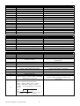
7.1
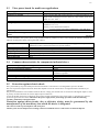
List of parameters .......................................................................................................................................................................... 39
7.1.1
Table of parameters........................................................................................................................................................................ 39
7.2
Description of the parameters ........................................................................................................................................................ 42
7.2.1
Probe set-up (“S” parameters)........................................................................................................................................................ 42
7.2.2
Regulation set-up (“R” parameters) ............................................................................................................................................... 42
7.2.3
Compressor and heater activity (“c” parameters)........................................................................................................................... 44
7.2.4
Fans (“F” parameters) .................................................................................................................................................................... 44
7.2.5
Defrost (“d” parameters) ................................................................................................................................................................ 45
7.2.6
Alarms (“P” parameters) ................................................................................................................................................................ 46
7.2.7
General machine configuration parameters (“H” parameters)........................................................................................................ 47
7.2.8
pLAN communication (“L” parameters)........................................................................................................................................ 49
8.
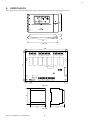
DIMENSIONS.......................................................................................................................................................................................... 50
9.
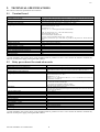
TECHNICAL SPECIFICATIONS......................................................................................................................................................... 51
9.1
Terminal board............................................................................................................................................................................... 51
9.2
Relay power board for stand-alone units........................................................................................................................................ 51
9.3
Triac power board for multi-zone applications .............................................................................................................................. 52
9.4
Common characteristics for components indicated above ............................................................................................................. 52
9.5
Protection against electric shock .................................................................................................................................................... 52
10.
SOFTWARE UPDATING........................................................................................................................................................... 53
10.1
Notes for the release 3.4 (and the following ones): ........................................................................................................................ 53
Aria
IMPORTANT WARNINGS
BEFORE INSTALLING OR HANDLING THE APPLIANCE PLEASE CAREFULLY READ AND FOLLOW THE
INSTRUCTIONS AND SAFETY STANDARDS DESCRIBED IN THIS MANUAL.
This appliance has been developed to operate risk-free and for a specific purpose, as long as:
• it is installed, operated and maintained according to the instructions contained in this manual;
• the environmental conditions and the voltage of the power supply correspond to those specified.
All other uses and modifications made to the device which are not authorised by the manufacturer are considered
incorrect.
Liability for injury or damage caused by the incorrect use of the device lies exclusively with the user.
Please note that the machine contains powered electrical devices and all service and maintenance operations must be
performed by specialist and qualified personnel who are aware of the necessary precautions.
Disconnect the machine from the mains power supply before accessing any internal parts.
The local safety standards in force must be applied in all cases.
Disposal of the instrument:
The controller is made up of metal and plastic components. To dispose all of these components refer to the environment
protection laws valid in your own country.
Carel code +030220306 rel. 2.1 dated 23/11/07
3
Aria
INTRODUCTION
Aria is an electronic controller for the management of direct expansion air-conditioning developed by Carel for the home and
commercial markets.
It features a room terminal which communicates with a power board installed on the air-conditioning unit itself.
With its accurately-designed appearance, it is ideal for the sector it is used in. Another important feature of the product is its ease
of use, with a large LCD display and a highly intuitive user interface.
Furthermore, unlike other existing products on the market, the connection of the actuators is handled by an electronic board
located directly on the machine's electrical panel, thus avoiding the need to lay large quantities of cables to the control itself.
The serial communication allows cabling reduction between the terminal and the power board to just 2 wires.
The instrument can manage both conventional units and heat pumps with up to a 3 heating and 2 cooling stages (in a single
refrigeration circuit); its operational flexibility is guaranteed by a parameter used to quickly configure the type of airconditioning unit being controlled.
A special version is also available for multi-zone applications, in which up to 30 terminals are located in different rooms,
measuring the local temperature and optionally humidity, then communicating with the control of the centralised airconditioning unit (pCO or pCO2).
1.
1.1
GENERAL CHARACTERISTICS
Functions
“Aria” is a Carel electronic microprocessor-based control designed by Carel to manage single or multi zone Air Conditioning units in
residential/commercial applications. “Aria” is organized into two integrated systems: a terminal, installed in the room, and a power
board for managing the actuators to be placed in the electrical panel of the Air Conditioning unit itself. The terminal is connected to
the power board using a two-lead cable, thus greatly simplifying installation.
The power board is available in two different models, depending on the specific application:
• one model for the control of stand alone air-conditioning units (relay power board)
• one model for the control of a motorized damper, where “Aria” is used for zone control (triac power board).
1.2
Terminal
The terminal is the heart of the system; it is fitted with an internal probe for measuring the ambient temperature (this may be remotelylocated in the duct) and can be supplied with an extra active-type probe (0/1Vdc output) for measuring the ambient humidity.
The instrument's user interface has been designed for ease of use, featuring:
• the use of a complete and large-sized liquid crystal display
• the ergonomic separation of the buttons for programming (on the side) from those used for the immediate modification of the
desired temperature (set point), placed on the front
• the back-lighting of the buttons and the display, useful when there is not enough light
• a built-in buzzer (can be bypassed using a specific parameter) which signals any operating anomalies of the unit, and also
follow the pressing of each button.
• The presence of an optional real time clock allows the instrument to be independently time-band programmed each of the
seven days of the week. Being fitted with an independent power supply, it constantly maintains the correct time even in the
case of interruption to the main power supply.
The terminal is very easy to install, as:
• just 2 leads connect the terminal to the power board
• the quick insertion terminals used allow the connection of the cables to the terminal using the rear shell of the box; the
electronic parts are connected at the end, as the front panel is closed.
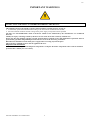
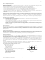
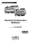
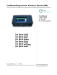
• the instrument may be programmed by simply copying the settings from another “master” machine, using a hardware “key”
KEY
TERMINAL REAR SHELL TO BE
WALL MOUNTED
TO
PROGRAM
KEY
3
2
1
3 2 1
Avss
B1
T+
T-
J2
GND
J1
24V
B2
Figure 1.2.1
Rx/Tx+
Rx/Tx-
Figure 1.2.2
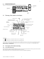
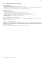
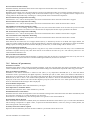
Figs.: 1.2.1 and 1.2.2 represent respectively the rear view of the terminal and the view of the rear shell.
Carel code +030220306 rel. 2.1 dated 23/11/07
4
Aria
The following “areas” of connection can be identified on the rear shell:
• T+, T- for the connection of the power board
• 24 V, AVss, B2 for the connection of a remoted Carel external active humidity probe (0/1Vdc output);
• AVss, B1 to remote the NTC temperature probe
• Rx/Tx+, GND, Rx/Tx- for connecting the terminal to the Carel pLAN local network
On the rear side of the terminal there are two further jumpers, J1 and J2, which are used as follows:
• J1: positioned between 1-2: Carel NTC temperature probe B1 remoted externally
positioned between 2-3: built in Carel NTC temperature probe B1
Note: For correct operation, do not connect the external temperature probe if the internal probe is used.
• J2: positioned between 1-2: probe (0/1Vdc output) B2 remoted externally
positioned between 2-3: built in humidity probe B2.
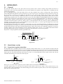
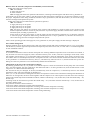
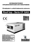
1.3
Power board for the control of stand alone air-conditioning units (code
TABASE5000)
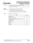
This board is installed inside the air-conditioning unit electrical panel; it is fitted with a set of terminals for connection to the
controlled devices (such as valves, compressors, fans). Its main features are:
• an analogue input for measuring the temperature of the external heat exchanger of a heat pump unit in order to control the
defrost cycles and condenser fan; for units without heat pump, or alternatively by excluding the defrosts, it may be used as
the outside temperature measurement to control free-cooling, free-heating and temperature set point compensation (see
paragraph 5.2.8 - Using probes B2 and B3 );
• 5or 7 digital outputs (relays) – according to the models – which allow the instrument to be used in a wide range of
applications (see H1 parameter);
• 3 multifunctional digital inputs (see 5.6).
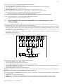
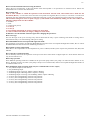
Figure 1.3.1
The following “areas” of connection can be identified on the board:
• terminals G and G0 for power supply (24Vac)
• terminals T- and T+ for connection to the terminal
• terminals ID COM, ID1, ID2 and ID3 for connection of the digital inputs
• terminals B3 and GND for connection of the NTC temperature probe on the external heat exchanger or in the outside air (see
paragraph “5.2.8 Using probes B2 and B3);
• terminals Cn-NOn for connection of controlled devices
Jumper J3, located in the centre of the card, is available for the selection of the digital input power supply. For more details see
Installation of the relay power board (stand-alone system – see ph. 3.3).
The board also features a green LED which provides a variety of information, coded according to the number of flashes emitted
in a 3 second period:
• 1 flash every 3 seconds: normal operation;
• 2 flashes every 3 seconds: serial communication error; the power board is not receiving the data sent by the terminal;
• 3 flashes every 3 seconds: serial communication error; the terminal is not receiving the data sent by the power board.
Carel code +030220306 rel. 2.1 dated 23/11/07
5
Aria
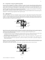
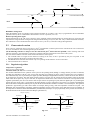
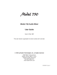
1.4
Power board for the control of a motorized damper (multi-zone system
codeTAZONE0000)
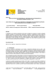
This board manages the motorized inlet air damper with a 3-point control, typically in multi-zone applications.
Its main features are:
• two 24Vac triac outputs to control damper opening/closing
• three multifunctional digital inputs (see 5.6);
• one analogue input, for automatic cooling / heating selection using the probe located in
the air duct (see 5.2.8).
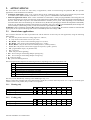
The following “areas” of connection can be identified on the board:
• G and G0 for power supply (24Vac)
• terminals T- and T+ for connection to the terminal
• terminals ID COM, ID1, ID2 and ID3 for connection of the digital inputs
• terminals B3 and GND for connection of a NTC temperature probe
• terminals OUT1, OUT2 and C to open and close the zone damper.
1.5
Codes
Figure 1.4.1
Here follow the codes of the Aria components.
Terminal
Terminal, basic model
Terminal, with programmer clock
Terminal, with programmer clock, back-lit display, buzzer
Terminal, with programmer clock, back-lit display, buzzer and built in humidity probe
Terminal with pLAN output
Terminal with pLAN output, back-lit display and buzzer
Terminal with pLAN output, back-lit display, buzzer and built in humidity probe
code
TAT00000W0
TAT0000CW0
TAT000RCW0
TAT000HCW0
TAT0000PW0
TAT000RPW0
TAT000HPW0
Tab. 1.5.1
Power boards
Description
Power board with 5 relays
Power board with 7 relays
Power board for zone control
code
TABASE5000
TABASE7000
TAZONE0000
Tab. 1.5.2
Programming hardware key
Description
Programming hardware KEY
Carel code +030220306 rel. 2.1 dated 23/11/07
code
TAKEY00000
Tab. 1.5.3
6
Aria
2.
APPLICATIONS
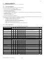
The Aria control can be used in a wide variety of applications, which are selected using the parameter H1. The possible
applications can be divided into two families:
• stand-alone applications, where “Aria” controls directly the air-conditioning units via relay power board. The power board
is available in two different models, with either 5 or 7 relays (part no. TABASE5000 and TABASE7000).
• multi-zone application control where a series of terminals are connected to a Carel pCO programmable control using the Carel
pLAN local network (pCO Local Area Network). In this situation the terminal ARIA measures the temperature and the humidity of
the zone, sends the data via pLAN to the centralized machine's controller pCO or pCO2, which, depending on the information
received from the other zone terminals (up to a maximum of 30), decides the operating logic and thus the temperature and humidity
of the air to be introduced into the duct. Each terminal is connected to triac power board (code TAZONE0000) which manages the
local zone damper (with floating control) in order to maintain the required ambient conditions.
WARNING: before modifying parameter H1 and thus changing the type of application, the machine should be switched OFF
(by keypad), as the outputs will change their function immediately after each change of H1.
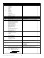
2.1
Stand-alone applications
The list below describes the value of parameter H1 and the function of each relay for each application, using the following
abbreviations:
• C1, C2 : relay for the control of cooling stages no.1 and no.2;
• V : relay for the control of the reverse cycle valve;
• R1, R2, R3 : relay for the control of heating stages no.1,2 and 3;
• R1, R2, R3 : relay for the control of heating stages no.1, 2 and 3;
• R1aux, R2aux : relay for the control of auxiliary heater 1, auxiliary heater 2;
• F1, F2, F3 : relay for the control of the supply fan at speed 1, speed 2, speed 3;
• OP : programmable output, via parameter H2;
• NU : Not Used;
• ALL: relay for alarm signalling;
• ES+ : Free-cooling or Free-heating damper opening relay;
• ES- : Free-cooling or Free-heating damper closing relay;
• P : water pool pump;
• Rp : pool water heating element.
The OP programmable output has the following functions, depending on the value of parameter H2:
H2
0
1
2
3
4
5
OP
Humidifier control
Alarm signal
Control of Fan on external heat exchanger
optional heaters for heating the pool water
Functioning mode remote signal (heating or cooling)
Comfort set point active signal
Tab. 2.1.1
The relays can be identified by referring to the numbering in. Fig. 1.3.1.
Relays 1 and 2 have normally-open (NO) and normally-closed (NC) contacts while relays from 3 to 7 only have normally-open
contacts. In the 5-relay model, relays 6 and 7 are not present.
2.1.1 Heating only
1 stage heating
2 stage heating
3 stage heating
H1
0
1
2
RL7
ES+
ES+
ES+
RL6
ESESES-
RL5
R1
R1
R1
RL4
NU
R2
R2
RL3
F1
F1
F1
RL2 RL1
OP
ALL
OP
ALL
R3
OP
Tab. 2.1.1.1
H1
3
4
RL7
ES+
ES+
RL6
ESES-
RL5
C1
C1
RL4
NU
C2
RL3
F1
F1
RL2 RL1
OP
ALL
OP
ALL
Tab. 2.1.2.1
2.1.2 Cooling only
1 stage cooling
2 stage cooling
Carel code +030220306 rel. 2.1 dated 23/11/07
7
Aria
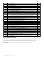
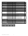
2.1.3 Conventional
1 stage cooling / 1 stage heating
1 stage cooling / 2 stage heating
1 stage cooling / 3 stage heating
2 stage cooling / 1 stage heating
2 stage cooling / 2 stage heating
2 stage cooling / 3 stage heating
H1
5
6
7
8
9
10
RL7
ES+
ES+
ES+
ES+
ES+
C1
RL6
ESESESESESC2
RL5
C1
C1
C1
C1
C1
F1
RL4
R1
R1
R1
C2
C2
R1
RL3
F1
F1
F1
F1
F1
R2
RL2 RL1
OP
ALL
R2
OP
R2
R3
R1
OP
R1
R2
R3
OP
Tab. 2.1.3.1
H1
11
12
13
RL7
ES+
C1
C1
RL6
ESC2
C2
RL5 RL4
RL3 RL2 RL1
C1
F1
R1AUX V
OP
F1 R1AUX
OP
V
AL
F1 R1AUX R2AUX V
OP
Tab. 2.1.4.1
H1
14
RL7 RL6
C1 R1AUX
2.1.4 Heat pump
single-compressor
dual-compressor 1Raux, 1 circuit
dual-compressor 2Raux, 1 circuit
2.1.5 Split system
single compressor heat pump
2.2
RL5
F1
RL4
F2
RL3
F3
RL2 RL1
V
OP
Tab. 2.1.5.1
Multi-zone control
This application can be selected by setting parameter H1=15; referring to Fig. 1.4.1, the meaning of the outputs is the following:
H1
15
zone controller
2.3
OUT1
Open
C
Common
OUT2
Close
Tab. 2.2.1
Display terminal
This application can be selected by setting parameter H1 = 16 and allows you to use the terminal as a display unit to measure the
temperature/humidity, connected to a pCO via pLAN serial line. There is no need then to use any Aria power card (neither
TABASE* nor TAZONE*).
2.4
Pool environments
climate and pool water control
2.5
RL7
C1
RL6
C2
RL5
R
RL4
F1
RL3
P
RL2 RL1
Rp
OP
Table. 2.4.1
H1
18
RL7
C1
RL6
C2
RL5
F1
RL4
ES+
RL3
ES-
RL2 RL1
V
OP
Table. 2.5.1
H1
19
RL7
C1
RL6
-
RL5
F1
RL4
F2
RL3
F3
RL2 RL1
OP
Table. 2.6.1
Heat pump + Energy Saving
dual-compressor heat pump with energy saving
2.6
H1
17
Split cooling only
dual-compressor heat pump with energy saving
Carel code +030220306 rel. 2.1 dated 23/11/07
8
Aria
3.
3.1
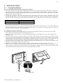
INSTALLATION
Terminal installation
For correct installation, the following warnings must be heeded:
• always disconnect the power supply before performing any operations on the board during assembly, maintenance or replacement.
• the terminal must be mounted vertically, allowing for air to circulate through the instrument's vent-holes. Avoid places
where the measurement of the ambient temperature by the internal sensor may be altered, such as outside walls, near doors
leading outside, in direct sunlight, etc.
• the cables for connection to the power board must be kept separate from other cables, using an individual raceway and,
possibly, shielded cables. In such a case connect the cable braid to terminal G0, reference for the 24Vac power supply (leave
the other side of the braid free). The maximum length allowed is 150m, according to the section of the cable, as per the table:
length of connection (m)
0 - 50
50 - 150
minimum cross-section (mm2)
0.5
1
Tab. 3.1.1
• when making the connection to the power board special attention must be paid to the polarity; the T+ pin on the terminal side
must be connected to the T+ pin on the power board; similarly for the T- pin ( however in case the cables are connected in
the opposite order the instrument will not be damaged).
The installation procedure is the following:
1. To detach the front panel of the terminal from the rear shell, place a flat-heat screwdriver in the slot in the centre of the
bottom side of the housing and release the locking flap (Fig. 3.1.1).
2. Raise the front panel using a “hinge” movement, using the upper edge of the instrument as the pivot and raising the lower
edge (Fig. 3.1.1);
3. To mount the rear shell to the wall, place the hole in the centre of the shell over the control cables of the instrument which
come out of the wall. The placement of the mounting holes has been designed to allow the instrument to be fixed onto
standard European flush mounting boxes conforming to standards CEI C.431 - IEC 670. If this is not available, use the
mounting holes on the shell as a guide for drilling holes into the wall and then use the screw and plug kit supplied.
4. Connect the cables to the terminals on the rear shell of the terminal, as indicated in Fig. 3.2.1 or Fig. 3.4.1, according to the
application you are facing to (stand alone or multi-zone).
5. Check the correct installation of the two jumpers J1 and J2 located on the rear side of the terminal (see Fig. 1.2.1)
6. Finally, close the instrument, moving the front panel onto the rear shell with a “hinge” movement, in the opposite way as
used for opening. First the long side of the front panel near the display is snapped onto the rear shell, then the opposite side,
being careful that the terminal pins slide into their corresponding female terminals.
Figure 3.1.1
Carel code +030220306 rel. 2.1 dated 23/11/07
9
Aria
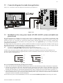
3.2
Connection diagrams for stand-alone applications
In Fig. 3.2.1 is shown the connection diagram for stand-alone type applications.
24 Vac/Vdc
stand-alone
Figure 3.4.1
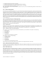
3.3
Installation of the relay power board (STAND ALONE system) and multi-zone
power board
The power board may be installed on the electric panel of the air-conditioning unit to be controlled. Its dimensions, DIN
standard compatible, allow installation on omega rail by means of suitable adapters available on the market. Connect the
actuators as in Fig. 3.2.1; the relays no.1 and no.2 have dual contacts, while the others have only one contact, normally open.
For a description of the devices controlled by each relay please refer to the Applications (pg. 7), according to the specific
configuration of the machine.
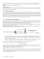
The digital inputs ID1, ID2, and ID3 are optically insulated and suitable for 24Vac/dc signals with “normally closed” logic (at
the contact opening there is alarm condition). To simplify the wiring it is possible to get the 24Vac/dc power supply from the
GND terminal (see Fig. 3.3.1). In fact J3 jumper can be placed as follows:
J3:
in position 1-2 (INT - ID COM): digital inputs powered internally (Fig. 3.3.1);
in position 2-3 (ID COM - EXT): 24Vac/dc power supply to be provided by the user (Fig. 3.3.2).
In order to get a real optical insulation, digital inputs power supply must be different from the one on the board that is 24
Vac/Vdc. In case the digital inputs are supplied by direct current, the IDCOM terminal must be connected to the positive pole,
ID1, ID2 and ID3 to the negative one.
GND
24 Vac/Vdc
ID COM
ID1
ID1
ID2
ID2
ID3
ID3
Fig. 3.3.1
Fig. 3.3.2
For correct installation the following warnings must be heeded:
• always disconnect the power supply before performing any operations on the board during assembly, maintenance or replacement.
• the cables for connection to the power board must be kept separate from other cables, using an individual raceway and,
possibly, shielded cables. In such a case connect the cable braid to terminal G0, reference for the 24Vac power supply (leave
the other side of the braid free). The maximum length allowed is 150m, according to the section of the cable, as per table 3.1.1.
• when making the connection to the power board special attention must be paid to the polarity; the T+ pin on the terminal side
must be connected to the T+ pin on the power board; similarly for the T- pin ( however in case the cables are connected in
the opposite order the instrument will not be damaged).
For the multi-zone power board (TAZONE0000), follow the same correct installation procedure for the relay power board.
Carel code +030220306 rel. 2.1 dated 23/11/07
10
Aria
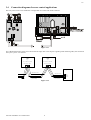
3.4
Connection diagrams for zone control applications
The triac power card is to be installed on a omega DIN rail. Connect the cards as follows:
Figure 3.4.1
For a detailed description of the pLAN local network usage refer to the respective guide (pLAN technical guide); the connection
to the pCO / pCO2 is as follows:
ARIA
e.g.:
L1=3, L2=1, L3=182
ARIA
e.g.:
L1=2, L2=1, L3=181
Rx/Tx- Rx/Tx+ GND
Rx/Tx- Rx/Tx+ GND
pCO
SHIELDED CABLE
SHIELDED CABLE
(AWG22, 1 twisted
pair with shield)
(AWG22, 1 twisted
pair with shield)
Figure 3.4.2
Carel code +030220306 rel. 2.1 dated 23/11/07
11
GND
RX/TXRX/TX+
J11
Aria
4.
USER INTERFACE
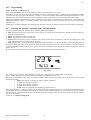
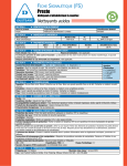
In Fig. 4.1 are shown the buttons and the indications managed by the terminal.
Immediate change
of the current set
point
CLOCK
SET
Side buttons for
programming
MODE
FAN
HOLD
RESUME
Fig.4.1
4.1
Meaning of the symbols on the display
Modify the value
Sensor B2 reading or ambient
temperature set point
Thermometer associated to
temperature measurement
Cooling ON
Ambient
temperature
Ambient temperature set point
displayed
Indicates B2 probe display
Exit
Fan operating mode
Continue
Time band indication
Heating ON
OFF
Set point override
Set point mode:
“unoccupied”, “comfort”,
“night”
Alphanumeric field
for time and info
Set point override
remaining hours
USER parameter
Fig. 4.1.1
In particular:
• the
symbol always on indicates actuators active in cooling mode.
• the
symbol always on indicates actuators active in heating mode.
If either symbol is flashing, this indicates that the actuators should be activated, yet external causes prevent them from doing so
(timers, alarms etc.). For a detailed description of the other symbols please refer to the paragraphs on the Description of the
button meaning and OPERATION.
4.2
Description of the button meaning
4.2.1 Front and Side buttons
The front buttons are the most important and thus are easier to reach, being large and placed on the front panel of the instrument.
These allow the immediate setting of the desired temperature (set point).
The side buttons allow access to all the other functions of the control. Immediate programming
Carel code +030220306 rel. 2.1 dated 23/11/07
12
Aria
4.2.2 Programming
4.2.2.1 F Button [^] and Button [v]
The [^] and [v] buttons allow the increase/decrease of the current set point by 1ºF or 0.5ºC.
Specifically, in time-band operating mode (indicated by the clock symbol), pressing the [^] and [v] buttons temporarily modifies
(overrides) the current set point. The duration, in hours, is shown at the bottom of the display and being decreased every hour
until the preset value elapses (parameter H8); the controller will then return to the previous operating mode (time bands).
During the modification phase the display shows the temperature set point, on the large display in the top left, in the place of the
measured temperature, if this is not already displayed on the small display in the top right (this function can be selected using
parameter H7)..
Modifications are acknowledged by the controller 5 seconds after releasing the buttons, when the related symbol stops blinking.
4.2.3 Selecting the machine's operating mode ([MODE] button)
Aria allows different operating modes of the air handling unit described below:
• OFF: the thermostat does not perform any control: however, it prevents the temperature from dropping below the safety low
limit(see paragraph 4.2.4.1);
• COOL: the thermostat controls cooling only;
• HEAT: the thermostat controls heating only;
• AUTO: heating and cooling control (automatic). The system switches from one function to the other depending on the value
of the ambient temperature in respect to the set point;
• FAN: ventilation only; you select the operating mode of the supply fan among 1, 2, 3, AUTO and OFF by means of the [FAN] button.
If you press the MODE button in the time-band operating mode, it displays the current operating mode for 5 seconds (indicated
by the corresponding blinking writing in the place of the clock). In the manual operating mode, instead, the operating mode is
always shown.
By pressing the button repeatedly the possible operating modes for the machine selected alternates.
Fig. 4.2.4.1
The operating mode selected is acknowledged 5 seconds after setting, when the related symbol stops blinking.
4.2.3.1 Selects the supply fan operating mode ([FAN] button, stand-alone version only)
Depending on the number of the supply fan speeds available and the machine operating mode, the FAN button scrolls through
the following modes:
o OFF: supply fan off (available only when in simple ventilation)
o 1: supply fan constantly at speed 1
o 2: supply fan constantly at speed 2
o 3: supply fan constantly at speed 3
o AUTO: supply fan switched on and off along with the actuators
When selected speed 1, 2 and 3, the symbol corresponding to the selected speed lights up for 5 seconds. Afterwards, the number
corresponding to the actual operating speed lights up; it may temporary differs from the one selected due to parameter c8 (delay
when varying the speed rates of the supply fan). Having set AUTO operation, when the fan starts, the text AUTO also appears
next to the fan symbol.
For details, see Output management.
Carel code +030220306 rel. 2.1 dated 23/11/07
13
Aria
4.2.4 Setting the temperature and humidity set points
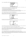
4.2.4.1 Setting the temperature set point category ([SET] button)
There are 3 possible “situation” available (unoccupied, comfort, night-time) indicated by the relative symbols, as well as the
“machine OFF” limit category:
• comfort set point (indicated by the symbol
):
the room is occupied, therefore a certain level of comfort is
required
• night-time set point (indicated by the symbol): the
room is occupied yet a lower level of comfort is required,
obtained “moving” the cooling and the heating stages a few degrees away from the comfort set point (like having a neutral
zone in between). This also results in reduced operating noise and energy consumption.
• unoccupied set point (indicated by the symbol
): typically used when the room is not occupied. The temperature
deviation with respect to the comfort set point
accepted is wider than the night-time set point, as cooling and
heating stages are engaged at temperature values much higher and lower than the set point. Energy consumption results
minimized.
Pressing the SET button in manual operating mode (without clock) changes the category currently used by the control. In timeband operating mode, on the other hand, the category is automatically set by the current program, as previously saved.
If [^] and [v] are pressed within 5 seconds of pressing SET (when category symbols are flashing) the set points of the selected
category can be modified. The default values for the various categories are:
set (°C / °F)
category
21 / 70
±2 / ±4
±4 / ±7
Tab. 4.2.5.1.1
Graphically the regulation obtained in the three different situations (and in AUTOmatic operating mode) is the following:
Comfort set
point
Differential
Differential
H ON
Differential
C ON
Comfort set
point
H ON
temperature
Comfort operations
Differential
C ON
Night
Deviation
Night
Deviation
temperature
Night operations
Comfort set
point
Differential
Differential
H ON
C ON
Unoccupied
Devation
Unoccupied
Deviation
Temperature
Unoccupied operations
When the unit is turned off (symbol
visualized in the display) or on in MODE=FAN, Aria will still start the heating stages
whenever ambient temperature drops below the low limit set with parameter P4 (Carel default value is= 10°C) in order to avoid
any damage in the room. In any case, this anti-freeze function can be excluded using parameter R14.
The right value of each category is related to the season and the personal idea of “comfort” of each user.
4.2.4.2 Setting the humidity set point ([SET] button for 3 seconds)
This can only be modified if the presence of the humidity probe has been enabled, using S1=2. The set point is modified using
the [^] and [v] buttons (modifications are acknowledged by the controller 5 seconds after releasing the buttons). The humidity
set point can also be set by parameter R5.
4.2.5 Programming the parameters
The user has numerous parameters available to customise the operation of the control, making it adaptable to a wide range of
needs and applications. The parameters have been divided into 3 levels:
1. DIRECT (D): directly accessible without protection code;
2. USER (U):
accessible with protection code (installer level);
3. FACTORY (F): accessible with protection code at factory level (manufacturer level).
Carel code +030220306 rel. 2.1 dated 23/11/07
14
Aria
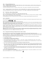
4.2.5.1 Setting the DIRECT parameters ([SET]+[HOLD] buttons)
Fig. 4.2.6.1.1
The display shows the first of the main machine operating parameters available. The parameters are scrolled using the [^] and
[v] buttons. Once having selected the parameter to be modified, proceed as follows:
• press the SET button to enter modifying mode, the selected parameter flashes;
• press the [^] and [v] buttons to modify the value of the parameter;
• press the SET button to confirm the modification.
To exit programming mode and accept the modifications to the parameters, press the HOLD button.
To exit programming mode, and NOT accept the modifications to the parameters, press the RESUME button, or wait for 1
minute of inactivity (the final 15 seconds are signalled by the flashing of the characters on the display).
4.2.5.2 Setting the USER parameters (installer, [SET]+[MODE] buttons)
These are the machine's “working” parameters, and are password-protected to avoid access by non-authorized persons. First of
all the access code 22 must be entered using the [^] and [v] buttons and confirmed using the SET button; when setting the code,
the right display shows the text Usr, telling the user what branch they are in.
Fig. 4.2.6.2.1
Proceed then as per the setting of the DIRECT parameters.
The USER parameters also comprise the DIRECT parameters. The USER-only parameters are signalled by the key symbol.
Fig. 4.2.6.2.2
Pressing the MODE button during the modification of a parameter enables a DIRECT parameter to become a USER parameter
and vice-versa. On displaying the parameter in question the key symbol will appear or disappear.
4.2.5.3 Setting the FACTORY parameters (configuration, [SET]+[MODE] buttons for more than 3 seconds)
These are the machine's configuration parameters. They are protected by a separate code from the USER code, to allow only
specific persons to access the data. First of all set the access code 177 using the [^] and [v] buttons, and confirm it using the SET
button; when setting the code, the right display shows the text Fac, telling the user what branch they are in.
Proceed as per the other parameters.
4.2.5.4 Setting the default parameters ([SET] + [RESUME] buttons when powering the controller)
These are pressed before switching on the machine and held until the settings have been entered, as signalled by the script ‘dEF’
displayed for 5 seconds. This operation allows the automatic setting of all the parameters contained in the Table 7.1.1 at their
default value (column “def” of the same table) except for the following parameters: S1, S2, S3, R8, R14, R18, R27, F7, F8, F9,
F10, F11, F12, F13, H1, H2, H15, H16, P12, d12.
Carel code +030220306 rel. 2.1 dated 23/11/07
15
Aria
4.2.6 Using the Hardware key
4.2.6.1 Copying parameters from the removable hardware key to the controller ([SET]+[^] buttons when powering Aria or
even only [^] button when powering Aria)
At the start of the operation the script “CE” appears; at the end “OK” or “NO” appears, according to the result of the data transfer.
4.2.6.2 Copying parameters from the controller to the removable hardware key ([SET]+[v] buttons when powering Aria)
At the start of the operation the script “EC” appear; at the end “OK” or “NO” appear, according to the result of the data transfer.
4.2.7 Real time clock and time-bands
4.2.7.1 Setting the time ([CLOCK] button, version with built-in clock only)
The value to be modified, that is, hours, minutes and day of the week, is selected by pressing CLOCK repeatedly, modified
using [^] and [v], and confirmed by pressing CLOCK again.
Pressing RESUME or after 60 seconds of inactivity, normal mode is resumed, and the modifications entered are lost.
4.2.7.2 Time bands
The time bands are the intervals of time into which a 24 hour day is divided; in each band, the operating mode of the unit can be
selected, between:
There are 6 possible time bands for each of the 7 days of the week.
When programming the time bands, these are indicated respectively by the letters t1-t2-t3-t4-t5-t6 on the small display in the top
right. When selecting one of the symbols, that is, comfort, night-time or unoccupied, for a time band, the unit will maintain the
set temperature value throughout the interval of time in question.
If selecting the Standby symbol for a time band, the unit will switch off throughout the interval of time in question. If a set point
category symbol (comfort, night-time, unoccupied) has then been selected for the following time band, the unit will
automatically switch back on. When a Standby time band is active, if the unit has not already been switched off using the Mode
button, the Standby symbol will blink.
Digital input ID3, if used as a serious alarm, does not have any effect if Aria is “OFF”, either due to the time bands or using the
Mode button. The unit can be temporarily activated during a Standby time band by pressing the Hold button (see par. 4.2.8.1).
Pressing Resume returns to the Standby time band (see par. 4.2.8.2).
4.2.7.3. Setting the time bands ([CLOCK] button more than 3 seconds)
The time bands refer only to temperature and not humidity regulation which is always based on the same set point.
The choice among the symbols is always highlighted by having the currently selected symbol flash and leaving the other
symbols constantly on; [^] and [v] are used to change the selection, making the next symbol in the sequence flash. To confirm
the selection and pass to the following field use the CLOCK button.
To set a program, after having pressed the CLOCK button for more than 3 seconds, the following steps must be performed:
• set the program start day
• set the start hour and minutes for the first band
• set the temperature set point category for the band
• after programming the band the symbols to ‘continue’ (<--|) and ‘end’(-->) appear, accompanied by the words “cont” and “end”
• ‘cont’ scrolls cyclically to the other bands, setting the start hours and minutes for the second band and so on (the current
band ends when the successive one starts)
• ‘end’ stops the programming for that day (thus cancelling any unprogrammed bands)
• after ‘end’ or after having programmed the final band for the current day, the day of the week programmed flashes followed
by the word ‘copy’. Use [^] and [v] to scroll to the other days, which flash in turn, confirming the day using the CLOCK
button, thus extending same program to the selected days. The symbols ‘cont’ (flashing) and ‘end’ and the script “cont” and
“memo” appear on the alphanumeric field
• use ‘memo’ to exit from programming mode and enable time-band operation. If there are days which have not been set, these
continue to use the previous program. On pressing the RESUME button, on the other hand, or after 1 minute of inactivity,
the modifications entered are lost.
• use ‘cont’ to program the remaining days
The time interval identified by time current band is shown on the display using the clock symbol, divided into 1-hour sections.
Thus, the time band from 3 to 7 o’clock is indicated as follows
Carel code +030220306 rel. 2.1 dated 23/11/07
16
Aria
4.2.8 Alarm management and general functions
4.2.8.1 [HOLD] button.
This button has the following functions:
• exits the parameter programming phase, saving the modifications entered;
•
on models with built in clock it passes from time-band to manual operation; in such a situation the word “HOLD” appears
and the comfort set point resumed, independently from any previous operating Set Point.
4.2.8.2 [RESUME] button.
This button has the following functions:
• exits from the current programming phase without saving the modifications;
• exits from overriding the set point in time band operation (models with real time clock);
• exits from manual operation (HOLD) and returns to time band operation (models with real time clock);
• resumes the comfort set point on models without real time clock;
• silences the buzzer.
4.2.8.3 [RESUME] button for more than 3 seconds
Manually resets the active alarms, cancelling the message on the display and de-energizing the alarm relay, if the alarm
conditions do not persist any more.
4.2.8.4 [^ ] + [v ] buttons simultaneously
This displays a value marked R SP in the lower display; the value corresponds to the effective start-up temperature of the
devices in the current situation. For example, in cooling operation with Comfort Set=21.0°C, Night-time Set=4.0°C (active), and
a compensation of +2.0°C, the effective start-up point of the compressors is 27.0°C, that is, the value displayed by R SP. This
may be useful in the test phase.
The firmware version is displayed by holding the arrow buttons for more than 3 seconds.
Carel code +030220306 rel. 2.1 dated 23/11/07
17
Aria
5.
5.1
OPERATION
General
The term SET POINT refers to the point which sets the position of the control’s working range within the interval of
measurement of the value being regulated. The set point thus identifies the regulation value (temperature or humidity) that the
control aims to maintain.
The term DIFFERENTIAL, on the other hand, refers to the value assigned to the control’s working range. Thus choosing a
narrow differential means that the control will operate very close to the set point, with minimum variance from the set value, yet
this also means an increase in the number of interventions of the control, thus reducing the life-span of the system’s
components. Vice-versa, choosing a differential which is too wide, while providing system stability, means that the values
reached during regulation may vary greatly from the set point. The terms DIRECT and REVERSE indicate the two types of
regulation logic for the device. The control uses “direct” logic when the controlled measurement (e.g. temperature or humidity)
tends to increase, aiming to reach the desired value (set point) (e.g. cooling, dehumidification); it uses “reverse” logic when the
controlled measurement tends to decrease, aiming, again, to reach the desired value (set point)(e.g. heating, humidification).
Automatic (AUTO) operation refers to when the device works in both “direct” or “reverse” logic according to the value of the
controlled measurement in respect to the set point.
The regulation set point for the “Aria” control is a “lateral band” type, that is the band identified by the differential is aside the
set point, graphically on the right or on the left of the set point (if we are respectively cooling or heating). Normally the actuators
are deactivated when the value of the controlled measurement is equal to the set point. For temperature regulation it is however
possible to define a zone centred around the set point, called the “Neutral zone” (see Fig. 5.1.1), inside of which the actuators
are already deactivated. This type of regulation is proportional. The stand-alone version can also perform
Proportional + Integral regulation (selected by parameter R19).
Haux relative set point
Haux Diff.
Differential
Haux ON
Differential
C1 OFF
C1 ON
C1 ON
Haux OFF
temperature
Set point
Neutral zone
Neutral zone
Figure 5.1.1
5.2
Stand-alone version
5.2.1 Proportional regulation algorithm
For the models with 1 regulation output, in “direct” operation without neutral zone5.2.1.1, Aria activates the output when the
controlled measurement exceeds the value of set point+differential and the output remains ON until the controlled measurement
decreases to the value of the set point. In “reverse” operation, still without neutral zone (Fig. 5.2.1.3), the device activates the
output when the controlled measurement falls below the value of set point-differential and the output remains ON until the
controlled measurement rises to the value of the set point.
Differential
Differential
C1 OFF
Set point
C1
C1 ON
C1 OFF
temperature
Set point +
Differential
Set point
C1
Neutral zone
C1 ON
temperature
Set point + Differential +
Neutral zone
Fig. 5.2.1.1
Fig.5.2.1.2
The Fig. no. 5.2.1.1 and 2 show respectively: direct without neutral zone and direct with neutral zone.
In AUTO operation (Fig. 5.1.1) the device can operate in both “direct” and “reverse” modes.. If the system has one or two
auxiliary heaters, these (if enabled) are activated according to the value of Haux set point (relative to the current temperature set
point) less the eventual neutral zone.
Carel code +030220306 rel. 2.1 dated 23/11/07
18
Aria
Differential
Differential
H1 ON
H1
H1 OFF
Set point Differential
H1 ON
temperature
Set point DifferentialNeutral zone
Set point
Fig. 5.2.1.3
H1 OFF
H1
Neutral zone
temperature
Set point
Fig. 5.2.1.4
The Fig. no. 5.2.1.3 and 4 show respectively: reverse without neutral zone and reverse with neutral zone.
For the models with 2 regulation outputs, in “direct” operation without Neutral zone (Fig. 5.2.1.5) the device activates the first output
(OUT1) when the controlled measurement exceeds the value of set point+1/2 differential; the second output is then activated (OUT2)
when the measurement exceeds the value of set point+differential. The outputs remain ON until the controlled measurement falls
below the value of set point+1/2differential (OUT2 goes off) and set point (OUT1 also goes off). In “reverse” operation without
Neutral zone (Fig. 5.2.1.7) the device activates the output OUT1 when the controlled measurement falls below the value of set point1/2 differential; output OUT2 is also activated if the measurement falls below the value of set point-differential. The outputs remain
ON until the controlled measurement reaches the value of set point-1/2 differential (OUT2 goes off) and set point (OUT1 goes off too).
Set point
Set point
C1,C2 OFF
C1
C2
C1,C2 OFF
C1,C2 ON
temperature
Neutral zone
Differential
Fig. 5.2.1.5
H1
C1,C2 ON
temperature
Differential
Set point
H1,H2 OFF
H1,H2 ON H2
temperature
Differential
C2
Fig. 5.2.1.6
Set point
H1,H2 ON H2
C1
H1
H1,H2 OFF
temperature
Neutral zone
Differential
Fig. 5.2.1.7
Fig. 5.2.1.8
R8=5
R3=2
R9=2
R3=2
R4=1 R4=1
R
12
C2
14
15
16
C1
C OFF
C1
17
19
C2
20
Temperature (°C)
21
R1=18
Fig. 5.2.1.9
The Fig. no. 5.2.1.7 and 8 show respectively: reverse without neutral zone and reverse with neutral zone.
In Fig.5.2.1.9 provides a description of a heat pump unit with 2 compressors and 1 auxiliary heater in AUTO operation, with the
following parameter settings: R1=18, R3=6, R4=2, R8=6, R9=2.
Humidity regulation (Fig.5.2.1.10) is very similar to the temperature one; humidification (=reverse) is driven by a single stage
(relay OP, programmed accordingly, H2=0) while dehumidification is performed by the available cooling stages which, according
to the model, may be 2. Graphically a 2 compressor unit with relay OP programmed to drive an humidifier is hereafter indicated:
Differential
Hum
ON
Differential
C1
Dehum
C2 100%
50%
Hum. set point
Fig. 5.2.1.10
Neutral zone is not available on humidity control.
Carel code +030220306 rel. 2.1 dated 23/11/07
19
humidity
Aria
5.2.2 Proportional + Integral regulation algorithm
If system’s point of equilibrium is required to correspond to the value of set point, more sophisticated regulation must be
imposed. Integral-type regulation must be added to proportional regulation (available as standard). Integral-type regulation acts
on the variation of the point of equilibrium from the set point, aiming to reduce this to zero. The integral time must be set; a
typical value for this parameter, recommended as an initial setting, is 600 seconds (10 minutes). The integral error is not
calculated at all points of regulation, but rather only when the measurement is located in the zone identified by the differential
plus 10%. Outside of this zone, proportional regulation only is performed.
Once PI regulation is activated, the control increases the integral error, which is added to the proportional error, in every instant:
this means that the instrument is constantly acting to reduce the total error being accumulated, with the result that the point of
equilibrium is continuously being brought nearer to the required set point.
5.2.3 Split operation
The machine model H1=14 allows the management of split-type units, that is single-compressor heat pump with the possibility
to manage a three-speed supply fan in the internal exchanger. The ability to modify through ventilation the overall capacity 0÷100% - of a single compressor based unit has led to the development of temperature control which is different from the one
available on the other selectable machine models (parameter H0). Given the set point and the differential, the following control
logic has been preferred, considered as being more efficient:
Haux relative set point
Haux diff.
Differential
Differential
C1 ON
(50% diff)
Haux ON
C1 ON
(50% diff)
Set point
C1 OFF
F3 F2 F1
temperature
F1 F2 F3
temperature
100% 66% 33% of 33% 66% 100% of
differential differential
Fig. 5.2.3.1
The compressor is in fact switched on at 50% of the temperature differential (both in heating and cooling), with the supply fan
already on at minimum speed; if the temperature continues to rise the fact of switching the supply fan to speed two at 66% and
speed three at 100% of differential allows the temperature to be smoothly brought back within the set point.
This system has the following advantages:
• on minimum temperature variations the supply fan is started (if it has not be set for continuous operation) at minimum speed,
circulating the air in the environment, overcoming any stratification of the air and providing a certain level of comfort.
• The compressor starts-up at 50% of the differential and no longer at 100%, thus accelerating the overall response of the
machine to changes in ambient temperature.
• When the compressor is running there are two further supply fan steps which allow modulation of the refrigeration power,
both on increase and decrease of the temperature. In practice, the efficiency of the machine is optimised accordingly the
variation of thermal load.
This logic is of course valid in heating, cooling and automatic operating modes. In addition, the neutral zone function is still
available, if necessary; when enabled the start-up point of the compressor is “moved” away from the set point of the value of the
neutral zone (as for other operating modes).
The supply fan is driven using 3 contacts, RL3, RL4 and RL5, activating the different speeds in mutual exclusion:
Haux relative set point
Differential
Differential
Haux diff.
Haux ON
50%
50%
C1 ON
C1 ON
Set point
C1 OFF
F3 F2 F1
100% 66% 33% of
differential
F1 F2 F3
33% 66% 100% of
differential
Neutral Neutral
zone zone
Fig. 5.2.3.2
Carel code +030220306 rel. 2.1 dated 23/11/07
temperature
20
temperature
Aria
• at minimum speed only relay RL5 is energised
• at medium speed relay RL5 is de- energised and relay RL4 is energised
• at maximum speed relays RL4 and RL5 are off and relay RL3 is energised.
The reverse sequence is adopted for switching off.
The configuration H1=19 is a variation of H1=14, where the reverse cycle valve and the heating element are absent; that is, a
cooling-only unit.
5.2.4 Defrost management
The defrost process (enabled if parameter d1=1) is activated in the heat pump units during heating, when the outside temperature
is very low and the coil of the external heat exchanger is getting frozen. The start of the defrost is determined by the drop in the
temperature of the external coil (measured by probe B3) below a certain threshold (parameter d3) for a minimum time
(parameter d5) and brings about the immediate shut-down of the external and supply fan and the inversion of the reverse cycle
valve; the compressors remain on. If enabled by parameter d8, the auxiliary heaters are also activated; in this case the internal
fan remains on. The end of the defrost may be based on time (parameter d2=0) or determined by the return of the temperature
(parameter d2=1) of the evaporator above a certain threshold (parameter d4) or by the opening of digital input ID3 (parameter
d2=2), in any case it must end within a maximum time period (parameter d6). The minimum interval between two defrost cycles
is set by parameter d7.
5.2.4.1 Forced defrost due to low outside temperature
If the temperature of the condenser (probe B3) falls below a certain temperature value (d11), even if the minimum time between
two defrosts has not elapsed (d7), a defrost is performed in any case. At the end of the defrost, the time d7 restarts. The program
may not perform more than one forced defrost at a time, and in fact after having ended the first, it waits for the end of the time
between two defrosts, even if the outside temperature B3 is lower than d11. Note that the forced defrost is valid if the start
temperature d11 is lower than the normal setting, d3.
5.2.4.2 Manual defrost
Parameter d13 can be used to activate a manual defrost, if the unit is operating in PdC mode. The defrost can be ended by using
parameter d13 again (setting it to 0) or alternatively when a temperature is reached (d4), or a maximum time elapses (d6), or by
pressure switch on a digital input; in the latter three cases parameter d13 changes from 1 to 0 automatically.
5.2.4.3 Compressor stops at start and end defrost
The compressor can be stopped at the start and the end of the defrost cycles. The defrost start sequence is the following:
1. defrost request
2. stop compressors
3. wait time d9
4. reversing valve
5. wait time d10
6. compressor starts and defrost is performed.
The end defrost sequence is the following:
1. end defrost reached
2. stop compressors
3. wait time d9
4. reversing valve
5. wait time d10
6. compressor starts (if required by the system).
If one of the two times d9 or d10 is equal to 0, the compressor is not stopped at the start or at the end.
5.2.4.4 Supply fan activation delay after defrost
If a defrost is performed without the support heaters (d8=0), the supply fan remains off. To prevent the fan from starting
immediately at the end of the defrost, sending cold air into the room, this can be delayed from the start of the compressors by a
time set using parameter F13.
5.2.4.5 Smart defrost cycles
The minimum time that must elapse between two defrosts, d7, can be automatically decreased if the defrost requests are so
frequent that the time d7 is considered too high. The time d7 is decreased if two successive defrosts are started when the time d7
has already elapsed, that is, were already requested by the system before the time elapsed, but were waiting for the start signal.
From this moment on, the time d7 is further decreased for each defrost that starts when the time has already elapsed. Vice-versa,
d7, after having been decreased, is increased a little at a time if the defrosts do not start so frequently, that is, are requested some
time after the time d7 has elapsed. The parameter defining the value that the time between defrosts is increased or decreased by
is d10, and is expressed in minutes.
Carel code +030220306 rel. 2.1 dated 23/11/07
21
Aria
The time between defrosts may be decreased by a maximum of 60% of the set value; if, for example, d7=20 minutes, it may be
decreased by a maximum of 12 minutes, and the minimum value it may assume is 8 minutes; it cannot be decreased below this
level. If d10=0, the function is disabled. When switching Aria off and on again, or after a blackout, the time d7 is reset to its
original value . Below is a time diagram relating to the intelligent defrost function, and to the compressor stops; as can be seen,
the temperature at the end of the defrost cycles is below the activation threshold two consecutive times, which therefore causes
the time d7 to be decreased.
Active defrost
Reverse cycle
Stop compressors
Temperature
d3
time
d9 d10
d9 d10
d7
d7
d5
d5 d9 d10
d9 d10
5.2.5 Dehumidification management
The process of dehumidification is initiated by activating the cooling actuators when the ambient humidity exceeds the humidity
set point + the corresponding differential, as described for “direct” operation.
In case two stages for cooling are available, the first one is engaged at 50% differential, the second one at 100%.
The process can only occur if:
• the machine selected is a conventional one, with cooling (compressors) and heating actuators (heaters), that is when
parameter H1 has a value between 5 and 10
• the process has been enabled (parameter R7=1)
• the humidity probe is present (parameter S1=2)
• the temperature does not fall below the set point - differential - possible neutral zone -0.5°C (priority is given to temperature
regulation). In such event, the process of dehumidification is interrupted to allow the ambient temperature to return to the set
point value; following this the process of dehumidification may recommence.
If more two compressors are available and compressors rotation has been enabled, the actuator to be activated by the
dehumidification process is determined as described in the section about paragraph Output management and under the heading
Compressor rotation.
In the event of cooling calls along with dehumidification requests, the number of cooling stages energized will vary according
the higher of the two requests.
Whenever in dehumidification process, the symbol of “ice” will lit (only if any of the heating actuators are not energized yet).
5.2.5.1 Dehumidification in Night-time or Unoccupied mode
In order to save energy, it may be useful to exclude dehumidification during the night or in periods when the environment being
climate controlled is unoccupied. To do this, use parameter H15. If H15=0 with the Night-time or Unoccupied set point active,
dehumidification is not performed. If H15=1 dehumidification is performed.
5.2.5.2 Dehumidification stop temperature
Dehumidification is in essence a cooling function that may lower the ambient temperature. To prevent the temperature from
decreasing too much, a minimum temperature value is used to disable dehumidification. This limit is: (Comfort Set–
Differential–0.5°C); below this temperature value, dehumidification is deactivated until the temperature reaches the Comfort set
point. The support heaters can be activated during dehumidification to increase the temperature; for all types of active set point
(Comfort, Night-time or Unoccupied) with dehumidification enabled, the heaters are activated immediately below the Comfort
set point, in order to keep the temperature high.
The diagram below refers to the situation with the Night time or Unoccupied set point active and dehumidification active. The
white steps refer to the normal activation thresholds of the heaters based on temperature (away from the set point due to the dead
band), while the grey steps indicate the activation of the heaters in the special case of dehumidification.
Carel code +030220306 rel. 2.1 dated 23/11/07
22
Aria
Dehumidification in
progress OR
Heating after stop
dehumidification
Dehumidification not active
Night-time or
Unoccupied Set
Night-time or
Unoccupied
R3
Stop dehumidification Temp.
Ambient temp.
Comfort Set
5.2.6 Automatic set point compensation
The temperature set point can be modified automatically based on the outside temperature value. If the outside temperature
reaches values that may affect the operation of the unit, for example, temperatures above 40 degrees in summer, the set point is
“worsened”, that is, increased; in this way, the level of comfort is decreased, yet this has a positive effect on energy savings and
the life of the machine. Another use of compensation is to maintain a maximum difference between the ambient temperature and
the outside temperature, to prevent, for example in shops, large differences between the outside and the inside and consequent
irritation to those who enter and exit. The function is described in the following diagram:
Compensation
COOLING COMPENSATION
30°C
R23=1
R25=5°C
12°C
25°C
18°C
R24=2
4°C
HEATING COMPENSATION
R3=3°C
R3=3°C
31°C
4°C
36°C
OUTSIDE TEMP.
R26=3°C
22°C
Setpoint=25°C
Cooling compensation starts when the outside temperature is greater than: Set point+R3+4°C. Following the example in the
diagram, with Set=25.0°C and R3=3.0°C, the compensation starts when the outside temperature is greater than 31.0°C (cooling
compensation) and less than 18.0°C (heating compensation). The intensity of the compensation can be set using parameters R23
and R24; these represent coefficients, and the higher their value, the lower the compensation for the same outside temperature
variation. For example, setting R23=1 leads to a 1.0°C increase in the set point for each 1.0°C increase in the outside
temperature; setting R24=2 leads to a 0.5°C decrease in the set point for each 1.0°C decrease in the outside temperature. Setting
R23 or R24 to zero disables the corresponding compensation.
The maximum set point increase and decrease values are set using parameters R25 and R26.
The function is enabled using parameter H16.
N.B. For the correct use of the external probe, see the paragraph: Using probes B2 and B3.
5.2.7 Free-cooling & Free-heating
The terms Free-cooling and Free-heating refer to the introduction of outside air into the climate controlled environment, in
favourable temperature conditions, to either heat or cool the environment and save energy. The outside air is introduced into the
room by modulating the degree of opening of a damper, controlled by two relays, one for opening and one for closing. The relay
activation time is the total damper stroke time (parameter L4). Whenever the control requests the total closing or opening of the
damper, the system increases the energising time of the corresponding relay by 25% to ensure complete closing or opening. At
each start-up, e.g. switching from Off mode to Auto mode, and whenever Aria is powered, the damper is immediately fully
closed.
Different options can be chosen (parameter R27): free-cooling only, free-heating only, both enabled, and in addition with or
without compressors. The with or without compressors option indicates that the compressors can or cannot start during freecooling / free-heating. In any case, if the outside temperature conditions are not favourable, the free-cooling and free-heating
functions are not activated and the compressors start normally.
Carel code +030220306 rel. 2.1 dated 23/11/07
23
Aria
The outside temperature is favourable for the activation of Free-cooling if:
Outside air temp. < (Ambient temp. – R28)
The outside temperature is favourable for the activation of Free-heating if:
Outside air temp. > (Ambient temp. + R28)
R28 defines the minimum differential between the outside and inside temperature.
The following diagrams explain this type of operation.
Diagram of free-cooling and free-heating operation without compressors (R27=1,2,3); it is assumed that the outside conditions
are favourable. As can be seen, the damper modulates across the entire amplitude of the temperature differential R3, completely
replacing the compressors.
100%
Free-heating
Free-cooling
Damper
100%
Damper
R3
Ambient temp.
R3
Setpoint
Diagram of free-cooling and free-heating operation with compressors (R27=5.6.7); it is assumed that the outside conditions are
favourable. As can be seen, the damper modulates across the entire amplitude of the temperature differential, but if the ambient
temperature increases or decreases to a value of 2*R3 above or below the set point, the compressors will start.
External Temperature
100% Free-heating
Compressors
Free-cooling
Damper
Damper
100%
Compressors
Ambient temp.
R3
R3
R3
R3
Setpoint
To prevent the introduction of outside air when the temperature differs too much from the ambient temperature, there is a
maximum value for the difference between the two that, if exceeded, disables the free-cooling and free-heating functions
(parameter R29); the functions are reset when the outside temperature is at least 2°C within the limit R29.
N.B. For the correct use of the external probe, see the ph. 5.2.8 Using probes B2 and B3.
5.2.8 Using probes B2 and B3
Three probes can be connected to ARIA: two NTC temperature probes (B1 and B3) and one active humidity or temperature
probe (B2). The first NTC probe, B1, is designed to measure the ambient air temperature.
The use of probes B2 and B3 changes automatically according to the functions chosen.
ACTIVE DEFROSTS (d1=1) ON UNIT PDC
AND/OR ACTIVE CONDENSATION (F7 different from 0)
Probe B3 is used for the defrost function and/or to manage the condensation.
Probe B2 is used to measure the humidity if S1=2; Compensation, Free-cooling and Free-heating can not be enabled.
Probe B2 can be used as the outside temperature measurement if S1=1; in this case the Compensation, Free-cooling and Freeheating functions can be enabled.
NEITHER ACTIVE DEFROSTS OR CONDENSATION
Probe B3 may be used as the outside temperature measurement; Compensation, Free-cooling and Free-heating can be enabled,
Probe B2 can be used to measure the humidity.
Carel code +030220306 rel. 2.1 dated 23/11/07
24
Aria
5.2.9 Output management
Compressor management.
When powering the controller, the compressor/s are activated after an initial delay, set by parameter R21. During the normal
operation the optimisation of the starting is managed using an intelligent activation program, as follows:
• - when a compressor is activated, it is not shut-down within a minimum running period (parameter c1);
• - once the compressor has been shut-down, it is not re-activated within a minimum stop period (parameter c2);
• - a set time interval must elapse between two successive start-ups of the same compressor (parameter c3).
• - the second compressor, if present, may only be started after a set interval (parameter c4) from the starting of the first
compressor;
• - when there are 2 compressors, compressor rotation is enabled if parameter R18 is set to 1.
Compressor rotation. Compressor rotation is a system which controls compressor activation in such a way as to equalise their
operating times. The operating logic when 2 compressors are activated is that the first to be started/stopped is the first to be
stopped/started. When just one compressor is activated (in a system with 2 compressors) this is done by alternating the
compressors used. After a certain operating period, set by parameter c7, the compressor maintenance required message is displayed.
Reversing cycle valve management
This is controlled by the HEAT/COOL/AUTO setting on the terminal or by digital input ID1 in the heat pump units.
Heat: heating mode, valve de-energized
Cool: cooling mode, valve energized
Auto: the state of the valve depends on the value of the ambient temperature in respect to the set point. The state of the
valve is changed, if required, at the moment the actuators are activated.
Parameter H14 can be used to choose the logic of the relay dedicated to the reverse cycle valve. When the unit is
switched off or when the set point has been reached, stopping the devices, the valve remains in its existing position,
until the next request.
Heater management
When the instrument is configured for 2 or 3 heaters, SEQUENTIAL heater management is used. The heaters are switched on/off
in sequence, with a time interval (parameter c8) between the activation of heater 1, always activated first, heater 2, always
activated second and heater 3, always activated third. During shut-down heater 3, if activated, is switched off first, then heater 2
and finally heater 1.
Auxiliary heater management
The auxiliary heater is activated, if enabled by parameter R10, when the heat pump system is not able to maintain the desired
temperature, such as when the outside temperature is too low. If this is an occasional occurrence, the compressors may be left
on; otherwise they are shut-down (selected by parameter R11), still respecting the time delays protection.
Supply fan management
The supply fan may feature from 1- to 3- speed operation. In order to reduce current absorbed during start-up, the activation of
the corresponding outputs is never simultaneous, but rather delayed by parameter c8. The button “Fan” selects the fan operating
mode (energized whenever at least one actuator is operating or always ON).
To reduce the stream of cool air in the ambient, the supply fan is stopped while defrosting except when the auxiliary heater are
set to be energized in such situation; this is performed in order to evacuate the energy provided. Using the MODE button the
“only ventilation” mode can be selected (“FAN” script appears in the alphanumeric field), disabling temperature and humidity
regulation.
Particularly, depending on the speeds of the fan available and the machine model selected, the symbols ‘1, 2, 3 and auto’ next to
the fan symbol, which alternate on pressing the FAN button, have the following meaning:
Only ventilation mode (enabled by the MODE button):
models with fan at single speed:
OFF: the supply fan is off
1: supply fan always on
2, 3, auto: not available
F1
F3
F2
Cooling
F1,F2,F3 ON
FAN OFF
models with supply fan provided with three speed rates (split unit):
OFF: the supply fan is off
1: supply fan always on at speed 1
2: supply fan always on at speed 2
3: supply fan always on at speed 3
auto: not available
Carel code +030220306 rel. 2.1 dated 23/11/07
25
1/3
2/3
diff/2
Setpoint
Fig. 5.2.6.1
Tamb
Aria
HEAT/COOL/AUTO mode (temperature and humidity control activated):
models with supply fan at single speed:
OFF: not available
1: supply fan always on
2, 3: not available
auto: the supply fan follows the operation of the actuators, switching on and off together with these if set by parameter F5.
In this mode you can also select a delay to start the supply fan after the actuators (parameter F1), to allow the exchanger to reach
the proper temperature before being ventilated, and one to stop it (parameter F2, still after the actuators), to remove the energy
from the exchangers and optimise the system.
models with supply fan provided with three speed rates (split unit):
OFF: not available
1: supply fan always on at speed 1
2: supply fan always on at speed 2
3: supply fan always on at speed 3
auto: the supply fan follows the operation of the actuators and modulates its speed according to the variation of the
ambient temperature from the current set point; below the set point the supply fan either switches off or remains on at the
minimum speed, according to parameter F5.
In this mode you can also select a delay to start the supply fan after the actuators (parameter F1), to allow the exchanger
to reach the proper temperature before being ventilated, and one to stop it (parameter F2, still after the actuators), to
remove the energy from the exchangers and optimise the system.
After a certain operating period of the supply fan, set by parameter F4, the replace supply fan filter message is displayed.
Fan Comfort management
With the parameter F5=2 the fan remains always ON with comfort setpoint and works automatically, that is to say in accordance
with the devices, with the night time setpoint and unoccupied setpoint; when Aria is OFF, it is OFF. This is a normal management
in some worldwide countries.
Anti-stratification
To avoid the stratification of the air and the consequent risk of having different temperature zones in the same environment, it
may be useful to activate the supply fan, after a maximum inactivity time. In fact, if the fan is operating in Auto mode, it must
start together with the devices, yet in particularly stable environments, where the temperature varies slowly, the devices may
also remain off for an extended period, and as a consequence the fan is not started. The anti-stratification function works based
on two parameters: a maximum fan inactivity time, F7, calculated only when the unit is on, and the forced start-up time F8.
Setting one of the two parameters to zero automatically disables anti-stratification.
Management of the Fan on the external heat exchanger
By selecting parameter H2(=2), it is possible to use the OP output to control one external fan in heat pump units. The external
fan is activated together with the compressors and deactivated after a set time (parameter F6) from the deactivation of the
compressors. It is deactivated when defrosting.
The external fan may be managed, as desired, simultaneously with the compressors, or alternatively based on the outside
temperature values. The choice depends on parameter F7.
If F7=1, 2 or 3, the external fan is managed on the bases of temperature values on the external heat exchanger that determine its
behaviour. In cooling mode, the fan is started together with the compressors for a time equal to F10, after this it starts and stops
based on the outside temperature thresholds F8 and F9; when the outside temp. > F9, the fan starts, when the outside temp. < F8,
the fan stops.
In heating mode, the external fan stops when the outside temp. > F11, and starts when the outside temp. < F12; the time F10 is
not used in heating mode.
The parameter F7 allows selection between:
0=fan starts with the compressors in both cooling and heating;
1=fan starts based on the outside temperature in cooling, starts with the compressors in heating;
2=fan starts based on the outside temperature in heating, starts with the compressors in cooling;
3=fan starts based on the outside temperature in both cooling and heating.
Carel code +030220306 rel. 2.1 dated 23/11/07
26
Aria
ON
COOL
OFF
F11
F12
F8
ON
T on the external heat exchanger
F9
HEAT
OFF
T on the external heat exchanger
Humidifier management
When the humidity probe is available on the terminal (parameter S1=2) and the “OP” relay is programmed to drive a humidifier
(parameter H2=0), this is commanded as described for “reverse” operation (5.2.1.10).
Remote operating mode signal
Setting parameter H2=4, the “OP” relay is driven by Aria to signal the current operating mode to an external device. In such a case, the
output will be energized while cooling and de-energized while heating (in any case, the “OP” relay is fitted with double terminals).
This indication is more reliable than the status of the reverse cycle valve, as the latter changes during defrosts.
5.3
Zone control version
Zone control is performed using a Carel pCO or pCO2 programmable controller placed in the centralized AC unit connected to
an “Aria” terminal for each zone through Carel pLAN network.
(All the following references to the pCO are also valid for the pCO2, unless otherwise specified). These exchange with each
other the parameters, the information required for regulation and other information on the status of the system.
The user interface differs from that on the stand-alone model in some aspects:
1. The CLOCK button no longer has the function of setting of the time, as this is provided by the pCO via pLAN. It still
however maintains the function of setting the time bands.
2. The MODE button alternates between the only two operating modes allowed: “AUTO” and “OFF”.
3. The FAN button has no function.
5.3.1 Regulation algorithm
Temperature regulation:
There are two possible modes.
Automatic mode (AUTO): this is normal way.
The essential information for the operation of the system is the operating mode (heating or cooling) that the pCO aims to maintain,
according to its algorithm. Until the “Aria” receives this value (the pCO operating set point), it does not perform any type of regulation.
This information may also be provided by the digital input ID1 (Heating/Cooling hardware selection), to allow the use of Aria wherever
pLAN network is not present. The pCO usually operates with two set points, one for cooling and one for heating. These are the limits
within which the set point may vary for each zone, as temperatures outside of the values can not be reached. It is not important for the
regulation performed by the “Aria” unit to know how the pCO chooses its operating set point (based on digital input or by evaluating the
requests from the various zone); it is important on the other hand for it to know what point it has chosen, as it is based on the difference
between the ambient temperature and the pCO set point that the terminal decides whether to modulate or close the dampers. The regulation
performed is proportional type with a lateral band. For example, during cooling, when the temperature exceeds the set point + the
differential, Aria opens the damper completely; when the temperature is below to the set point, on the other hand, it closes it completely. If
the temperature is within the lateral band identified by the differential, the damper is open proportionally in the position shown below by
the Set Point based on the excursion time of the dampers (parameter L4).
Damper % opening
Damper % opening
HEATING
100%
COOLING
100%
temperature
setpoint differential
Setpoint
"Fire" symbol
lit
temperature
pCO setpoint
pCO setpoint
"Fire" symbol
off
"ice" symbol off
Fig. 5.3.1
Carel code +030220306 rel. 2.1 dated 23/11/07
27
Setpoint
setpoint +
differential
"ice" symbol lit
Aria
In time-band operation mode, pCO must be provided with the real time clock option (part no. PCOCLKMEM0); the current
time is in fact then sent to the zones through the network. The pCO2, on the other hand, does not require an optional board.
OFF mode
The damper is totally closed and no regulation is performed.
Humidity regulation
The rate of opening of the damper is decided according to the temperature; the pCO can however decide the percentage of
humidity to introduce into the duct according to the values arriving from the individual zones related to the ambient humidity
and the required humidity (humidity set point).
5.3.2 Damper management
At start-up the instrument forces the dampers to close completely in the excursion time equal to the one set by parameter L4 +
10%. During normal operation, when temperature regulation is requested the control opens and closes the damper with a
minimum variation of 5% from the total excursion time. If the damper is required to close to more than 90% of total closure, the
control in this case first closes the damper completely and then returns to the required value. The same is true for opening. These
actions, as per the total closing of the damper at instrument start-up, allow the control to precisely calculate the degree of
opening of the damper at each moment, even if there is no direct feedback from the damper to the control. Finally, when the
control is OFF, it completely closes the damper, once again within the set excursion time +10%.
5.4
Pool environment management
Aria is also ideal for the control of pool environments, where it is important to control the pool water temperature and the
humidity and temperature of the surrounding environment. A special configuration has been designed for this purpose, H1=17,
where the relay manages the heaters and a pump for the water, and compressors, heaters and fans for the air. The probes are used
to measure the water temperature (B3) and the ambient temperature (B1) and humidity (B2).
Optional water heaters can be managed by the optional relay, enabling them by setting parameter H2=3.
The following diagram summarises the management of the devices based on the water temperature and the ambient humidity;
these are the two most important measurements.
WARNING: the ambient temperature probe may at any moment activate the ambient heating and cooling devices, so as to
maintain the Comfort, Night-time or Unoccupied temperature set point.
DEHUMIDIFICATION
WATER HEATER NO. 2 (OPT)
DEHUMIDIFICATION IF
REQUESTED BY THE HUMIDITY
PROBE
WATER HEATER NO.1
R14
Water Temp.
R2
1. If: (Pool Set - Pool Diff.) < T.pool < Pool Set → activation of ambient air dehumidification (fan, compressors and
possibly post heating) and pool heating (the hot gas is sent to the pool’s heater). The humidity probe is not considered.
2. If: T.pool < (Pool Set - Pool Diff) → activation of ambient air dehumidification and pool heating with two heaters. The
humidity probe is not considered.
3. If: T.pool > Pool Set → the humidity probe is considered: if dehumidification is not requested, all the devices are
deactivated; with high humidity, activation of dehumidification (fan, compressors and possibly post heating).
The priorities are: 1= Ambient air dehumidification; 2=Heating water; 3=Ambient air-conditioning.
The parameters used to manage the water set point and differential are R2 and R14.
PUMP MANAGEMENT
The pump usually operates in accordance with the devices, that is, with the water heaters; if no heater is active, the pump
remains off. The pump can also operate in continuous mode, and in this case the choices are: only in Unoccupied mode, or in all
operating categories (Comfort, Night-time, Unoccupied). Parameter H18.
For the management of the water flow switch, see paragraph 5.6.
IMPORTANT: given that in environments such as pools, the atmosphere is very aggressive due to the presence of chlorine, Aria
should be installed in a protected place or in a separate room, leaving only the probes in the pool environment being controlled.
Use Aria terminals fitted for remote probes (codes TAT000R…) and temperature and humidity probes for industrial use or in
any case with good atmospheric resistance.
Carel code +030220306 rel. 2.1 dated 23/11/07
28
Aria
5.5
pLAN connection
Even though connection to a pLAN network is designed mainly for the zone control version, the stand-alone version may also
be connected to a Carel pCO local network. Connection is made using the RS-485 standard, with 2 leads and asynchronous halfduplex serial transmission. To overcome the fact that the code for the “Aria” control resides in ROM and thus can not be
reconfigured according to the devices which make up the network (as it is normally done for pCO devices), some limits have
had to be introduced in respect to normal pLAN network management:
• Aria can receive data from any pCO board, yet can only send data to the pCO board whose network address is set by parameter L2;
• incoming data is identified using the address described in the following tables (RX INDEX ADD);
• outgoing data is written to the physical address (RX INDEX ADD * 2) + (L3*256) of the device with network address set by parameter L2.
The data is only transmitted in the case of variations to the data themselves, except for the parameters with address from 1 to
111 which are only sent on explicit request (var. 156). In order not to overcharge the management of such variations, the
remaining variables have been divided into the following groups:
• analogue variables from 138 to 150;
• integer variables from156 to 170;
• binary variables from 171 to 186.
The variation of one of the variables in the group means the whole group will be sent.
The range of values allowed is indicated in brackets; when there are no numeric indications or references to other parameters,
the first identifier has a value of zero, and the successive ones in the list have values in increasing order; example: (OFF, AUTO,
SPD1, SPD2, SPD3) means (0, 1, 2, 3, 4). Some data is visible both as variables and as parameters; if accessing a set point as a
parameter rather than as a variable, the modification will NOT be accepted, as delayed saving is required, which is only possible
when accessing as a variable. Following is a description of the information which may be exchanged between the “Aria”
controller and the pCO or pCO2.
5.5.1 List of variables
If the variation field, in the brackets, contains some nouns, they are the meaning of the values 0, 1, 2 … of the parameter.
For ex. R19 (P, P+I) means 0=P, 1=P+I.
In the parameters where there is only (0÷1) , 0 means NO,while 1 = YES, i.e. enabled or not enabled function.
D IGI TA L
RX INDICES
171
172
173
174
175
176
177
178
179
180
181
182
183
184
185
186
READ
WRITE
alarm reset
hardware reset
send forced parameters
output status set by remote
force buzzer
control status (standby; active)
remote alarm (not activated in OFF)
ID1 from remote
ID2 from remote
ID3 from remote
manual defrost
force ON (simulates the MODE button)
-
ID1 if enabled
ID2 if enabled
ID3 if enabled
buzzer status (mute; active)
control status (stand-by; active)
remote alarm
alarm status (0=no alarm; 1=alarms present)
AUX
YES
YES
YES
YES
YES
YES
YES
ANA LOG
RX
INDICES
138
139
140
141
142
143
144
145
146
147
148
149
150
151
READ
WRITE
probe B1
probe B2
probe B3
current temperature set point
UNOCCUPIED set point
COMFORT set point
NIGHT-TIME set point
temperature differential
remote set point
effective temperature set point R SP
Output percentage 0…10 V
Carel code +030220306 rel. 2.1 dated 23/11/07
temperature set point in Manual (without clock)
UNOCCUPIED set point
COMFORT set point
NIGHT-TIME set point
temperature differential (R3)
remote set point from pCO or pCO2
remote probe B1 (if bit 0=1, variable L5)
remote probe B2 (if bit 1=1, variable L5)
remote probe B3 (if bit 2=1, variable L5)
-
29
AUX
YES
YES
YES
Aria
I N T EG ER
RX INDICES
READ
WRITE
AUX
output logic status
Bit meaning
156
157
158
159
160
161
162
163
164
0= Compressor 1
1= Compressor 2
2= Valve
3= Heater 1
4= Heater 2
5= Heater 3
6= Fan speed 1
7= Fan speed 2
8= Fan speed 3
9= Humidifier
10= Alarm system
11= External fan
12= Water pool pump
13= Pool water heating element 1
14= Pool water heating element 2
15= Not used
-
percentage of damper opening
humidity set point
local clock HOURS
local clock MINUTES
local clock DAY
manual operating mode (AUTO, COOL, HEAT, FAN-ONLY)
fan operating mode (OFF, AUTO, SPD1, SPD2, SPD3)
Alarm signal 1
bit0: compressor maintenance alarm 1: HR 1
bit1: compressor maintenance alarm 2: HR 2
bit2: supply fan maintenance alarm: HR F
bit3: high temperature alarm: HI T
bit4: low temperature alarm: LO T
bit5: alarm from digital input: E ID
bit6: alarm from pLAN: REM
bit7: defrost over maximum time alarm: E DF
bit8: EEPROM error at boot: EE
bit9: run-time EEPROM error: EE
bit10: not used
bit11: terminal communication error: E SR
bit12: power board communication error: E TR
bit13: NTC control probe error: E1
bit14: 0/1Vdc probe error: E2
bit15: power board probe error: E3
humidity set point (no write if is in parameter modification mode)
local clock HOURS
local clock MINUTES
local clock DAY
manual operating mode (AUTO, COOL, HEAT, FAN-ONLY)
fan operating mode (OFF, AUTO, SPD1, SPD2, SPD3)
YES
YES
YES
-
Alarm signal 2
165
bit 0=pool pump alarm P AL
bit 1=fan thermal cut-off alarm Th F
bit 2=not used
bit 3=not used
bit 4=high humidity alarm HI H
bit 5=low humidity alarm LO H
bit 6=low pressure alarm LO P
-
machine status flag
166
bit 0=clock present (internal or remote)
bit 1=clock operating correctly
bit 2=internal clock present
bit 3= 0->manual / 1->time bands
bit 4=not used
bit 5=options present
167
-
168
-
169
170
-
set point category
(UNOCCUPIED, COMFORT, NIGHT-TIME, STAND-BY)
Temperature operating mode
(AUTO, COOL, HEAT, FAN-ONLY)
If var 162 = {HEAT, COOL} var 170 = var 162
If var 162 = ONLY-FAN var 170 = COOL
If var 162 = AUTO, depending on TAMB and the set point:
COOL
HEAT
set
Carel code +030220306 rel. 2.1 dated 23/11/07
set+dead zone
30
output status for remote control from pCO or pCO2 (the write is
significant if enabled by variable 177; See description variable
156
remote probe alarm (the write is significant if enabled by
parameter L5 (bit0, bit1, bit2):
bit0: probe B1 error
bit1: probe B2 error
bit2: probe B3 error
set point category in manual operation (UNOCCUPIED,
COMFORT, NIGHT-TIME, STAND-BY) if in time band mode,
the write is enabled if bit 7 of parameter L5 is equal to 1
-
YES
YES
YES
Aria
PARAMETERS
RX
INDICES
1
2
3
4
5
6
7
8
9
10
11
12
13
14
15
16
17
18
19
20
21
22
23
24
25
26
27
28
29
30
31
32
33
34
35
36
37
38
39
40
41
42
43
44
45
46
47
48
49
50
51
52
53
54
55
56
DESCRIPTION
S2
S3
S4
S5
R1
R4
R8
R9
R12
R13
R2
H17
C5
C6
C7
F3
F4
d3
d4
P3
P4
S1
S6
S7
S8
R5
R6
R7
R10
R11
R16
R17
R18
R19
R20
R21
C1
C2
C3
C4
C8
F1
F2
F5
F6
d1
d2
d5
d6
d7
d8
P1
P2
P5
H1
H2
57
H3
58
H4
59
60
61
62
63
64
65
66
67
68
H5
H6
H7
H8
H9
H10
H11
H12
H13
L1
lower extreme of the range of temperature/humidity probe B2 measurements (-150..S3)
upper extreme of the range of temperature/humidity probe B2 measurements (S2..150)
offset to apply to the temperature measurement by probe B1 (-12.0..12.0)
offset to apply to the temperature measurement by probe B2 (-12.0..12.0)
pool set point (R12..R13)
temperature dead zone (0..10.0)
relative set point for support heaters (0..50.0)
differential for support heaters (1.0..22.0)
minimum allowed limit for the temperature set point (0..R13)
maximum allowed limit for the temperature set point (R12..50.0)
pool temperature differential (1.0..10.0)
pump alarm delay (0..600)
compressor hour counter 1 (0..19.9)
compressor hour counter 2 (0..19.9)
compressor hour counter maintenance threshold (0..10.0)
supply fan hour counter (0..19.9)
supply fan hour counter maintenance threshold (0..10.0)
start defrost temperature (-30.0..d4)
end defrost temperature (d3..50.0)
high temperature alarm threshold (P4+1..150)
low temperature alarm threshold (0..P3-1)
type of probe B2 (0, 1, 2) (0=Absent, 1=0/1V temperature, 2=0/1V humidity)
digital filter for input B1 (1..15)
temperature unit of measure (0=°C, 1=°F)
select source for probe B1 (0, 1) (0=internal, 1=external)
humidity set point (R16..R17)
humidity differential (R16..R17)
enable dehumidification (0..1)
enable support heaters (0..1)
enable compressors with support heaters (0..1)
minimum allowed limit for the humidity set point (0..R17)
maximum allowed limit for the humidity set point (R16..100)
enable compressor rotation (NO, NORMAL)
type of control (P, P+I) (0=P, 1=P+I)
integration constant for PI algorithm (20..999)
control delay (0..600)
minimum compressor on time(0..300)
minimum compressor off time (0..900)
minimum time between two starts of the same compressor (0..900)
minimum time between starts of two compressors (0..150)
interval between heaters on / supply fan speed change (0..60)
supply fan start delay (0..10)
supply fan stop delay (0..180)
supply fan always on (0..1)
external fan stop delay (0..180)
enable defrost (0..1)
type of end defrost (0, 1, 2) (0=time, 1=temperature, 2=from ID3)
minimum start defrost time (10..120)
maximum defrost duration (1..900)
delay between two defrost requests (10..180)
support heaters in defrost (0..1)
enable buzzer (0..1)
type of alarm from digital input ID3 (0, 1) (0=signal only, 1=serious alarm)
delay for high/low temperature/humidity alarms (0..120)
machine model (0..19)
function of the programmable output (0, 1, 2, 3, 4, 5) (0= humidifier; 1=alarm; 2=external fan; 3=pool heater;
4=operatine mode signal; 5=Comfort mode signal)
function of digital input ID1 (0, 1, 2, 3) (0=absent; 1=remote cooling/heating selection; 2=alarm filter;
3=fan thermal cut-off alarm with “th F”signal)
function of digital input ID2 (0, 1, 2, 3) (0=absent; 1= remote ON/OFF; 2=water pump alarm with “P AL”signal;
3=low pressare alarm with “LO P”signal)
function of digital input ID3 (0, 1, 2, 3) (0=absent; 1= general alarm; 2=end defrost; 3=remote ON/OFF)
lock keypad (0..1)
select display on LCD (B2, CURRENT SET POINT, B3)
set point override time (0.24)
clock display 12/24 hours (0..1) (0=24h, 1=12h)
LCD contrast (-25..25)
enable button click (0..1)
back-lit front panel buttons at rest (0..1)
enable clock (0, 1.2.3.4.5.6) (0=disab., 1=local, 2.3.4=remote, 5=loc. without bands, 6=rem. without bands)
serial device address (1..31 – 1..207)
Carel code +030220306 rel. 2.1 dated 23/11/07
31
AUX
Aria
69
70
71
72
73
74
75
76
77
78
79
80
81
82
83
84
L2
L3
L4
L5
SP5
dev9
R28
R23
R24
C9
C10
P6
H14
H15
R25
R26
R27
85
86
87
88
89
90
91
92
93
94
95
96
97
98
99
100
101
102
103
104
105
106
107
108
109
110
111
112
P7
P8
H16
P9
P10
P11
P12
S9
S10
d9
d10
F10
F7
F8
F9
F11
F12
d12
F13
d11
F14
F15
d13
H18
R29
R14
L6
pLAN destination address (0..31)
pLAN page (0..255)
damper stroke time (1..900)
select alarm source (0..255)
firmware version (0..255)
machine operating status (0..255)
free-cooling/free-heating differential (0.5..15.0)
K+ for temperature set point compensation (0..10.0)
K- for temperature set point compensation (0..10.0)
compressor hour counter 3 (0..19.9)
compressor hour counter 4 (0..19.9)
delay in alarm from input ID3 (0..600)
select active valve status (0, 1) (0= normal logic, 1=opposite logic)
enable dehumidification in UNOCCUPIED and NIGHT-TIME (0..1)
minimum limit for the entity of set point compensation (-10.0..0)
maximum limit for the entity of set point compensation (0..10.0)
type of free-cooling/free-heating (0, 1, 2, 3, 4, 5, 6, 7) (0=disabled; 1=free-cooling without compressors;
2=free-heating without compressors; 3=free-cooling+free-heating without compressors; 4=disabled; 5=free-cooling
with compressors; 6=free-heating with compressors; 7=free-cooling+free-heating with compressors)
low humidity alarm threshold (0..P8)
high humidity alarm threshold (P7..100)
enable set point compensation (0..1)
delay in low pressure alarm on ID2 in normal operation (0..900)
delay in low pressure alarm on ID2 in heating with heat pump (0..900)
delay in low pressure alarm on ID2 in defrost (0..900)
type of reset for low pressure alarm on ID2 (0, 1, 2, 3, 4, 5) (0=automatic; 1=manual; 2..5=number of automatic
resets within 1 hour from the first alarm, then manual reset)
digital filter for input B2 (1..15)
digital filter for input B3 (1..15)
pause after compressors stop in defrost (0..180)
pause after reversing of the cycle in defrost (0..180)
external pre-ventilation time for condensation control (0..180)
enable condensation control in HEAT and COOL mode (0, 1, 2, 3) (0=disabled; 1=enabled in Cooling;
2= enabled in Heating; 3= always enabled)
external fan stop temperature for condensation control in cooling. (0.0..F9)
external fan start temperature for condensation control in cooling (F8..60.0)
external fan stop temperature for condensation control in heating. (F12..50.0)
external fan start temperature for condensation control in heating. (0.0..F11)
entity of intelligent increase/decrease in interval between defrosts (0..36)
supply fan start delay after compressors ON at end defrost (0..180)
forced defrost temperature (-50.0..50.0)
supply fan inactivity time to activate anti-stratification (0..999)
duration of ventilation for anti-stratification (0..99)
manual defrost (0..1)
pump configuration (ON DEMAND, CONTINUOUS, CONTINUOUS IN COMFORT)
compressor disable differential |TAMB – TOUT| (0..50.0)
enable anti-freeze (0..1)
serial protocol type (R) and I/O board presence (W) (0 to 6), bit2 (weight 4) read/write used to disable
the error “E SR”
Notes on switching the machine off and on
The unit can be switched OFF and ON from the keypad using the Mode button, by opening digital input (2 or 3) or simulating the
opening of the same by pLAN through variable 172 (only if L5=32 and H4=1) or controlling digital input 3 via pLAN with the
variable 173 (only if L5=64 and H5=3); in any case “who” turns the unit OFF always has priority over “who” wants it ON again.
However, on setting variable 185 by pLAN forces the unit ON, no matter if it was previously turned off by keypad or ID2.
AUX variables
The variables declared to be AUX are stored in RAM and must be initialised by pCO when powering Aria.
Carel code +030220306 rel. 2.1 dated 23/11/07
32
Aria
5.6
Digital inputs
These are physically located on the power board and need to enabled via the terminal, by setting the corresponding parameters
H3, H4, and H5 (they may derive from pLAN network if enabled by parameter L5).
ID1: Heating/Cooling selection - Filter Alarm – fan thermal cut-off alarm digital input
If H3=0 the input is disabled.
If H3=1 the unit operating mode is forced to be heating or cooling; this has priority over the commands sent by keypad (open
contact: Cooling/Summer operations, closed contact: Heating/Winter operations)
If H3=2 it has the function of non-serious alarm input, signalling the need to change the fan filter (open contact: clogged filter
alarm, closed contact: no alarm).
If H3=3, digital input ID1 may be used to control the supply fan thermal cut-off alarm; this is an immediate alarm showing Th F
blinking, and shuts down all the devices. Manual reset.
Selecting the fan thermal cut-off switch with H3=3 modifies the effect of the general alarm on ID3 if this is used as a serious
alarm (H5=1 and P2=1):
• With H3=3, H5=1, P2=1 if the alarm on ID3 goes off, all devices are stopped, except the supply fan.
• With H3≠3, H5=1, P2=1 if the alarm on ID3 goes off, all devices are stopped.
ID2: ON/OFF – water pump alarm – low pressure alarm digital input
If H4=0, the input is disabled.
If H4=1 and the contact is detected open, Aria is switched off independently from the keypad commands. If the contact is closed
Aria is enabled and operates depending on the keypad commands.
If H4=2, digital input ID2 is used to connect a water flow switch; if, within a certain time (H17) after starting the pump, the flow
switch is not yet closed, an alarm is generated, with P AL blinking, and the pool pump and heating functions are deactivated until the
alarm is reset, automatically. For further information, see the paragraph on Pool environment management.
If H4=3, digital input ID2 is used to manage the low pressure alarm; this is an alarm with different delay times, according to the
operating mode (P9=delay in cooling, P10=delay in PdC, P11=delay in defrost). The effect is to shut-down the compressors and the
external fan (if present), and the text LO P blinks on the display. The parameters P10 and P11, if set to 0, disable the alarm in the PdC
and/or defrost modes. The alarm may not on the other hand be disabled in Cooling mode, so that if P9=0 the alarm is immediate.
The reset may automatic, manual or mixed, as desired. The selection is made using parameter P12, which has the following
values: 0=always automatic reset; 1=always manual reset; 2..5=number of automatic resets, the following alarm is manual reset.
The count of the number of alarms generated refers to a period 1 hour from the first alarm; after this period the count is reset and
starts from 0 again. “Mixed” management allows the possibility to restart the unit in the event of an alarm, avoiding service
intervention unless strictly necessary.
ID3: General alarm end defrost – Remote On/Off digital input
If H5=0, the input is disabled.
(H5=1) The digital input takes the function of general alarm input In this case another parameter (P2) determines the response of
the control to this alarm; only visualization without any effect on the outputs (P2=0), or a serious alarm that activates the alarm
relay and blocks all the outputs (P2=1).
The general alarm is delayed by the time set for P6.
If H5=2, the opening of the contact ends the defrost cycle; for this to occur, parameter d2, end defrost mode, must in any case be equal to
2.
If H5=3, the input is used as a Remote On/Off using the same logic described for input ID2. This function is repeated in two
inputs to allow the possibility of using it together with the Low pressure alarm function.
5.7 Supervisor
ARIA can be connected to a supervisor installed on a PC, via RS485 serial line. The CAREL communication protocol is used in
this case, however, the CAREL Gateway also allows connection via Modbus and other protocols. The three-lead RS485 line is
physically connected using the same connector as the pLAN line, therefore the Aria terminals used must feature the pLAN
option (codes TAT…PW0). Parameter L6 is used to select between pLAN or RS485 line. The communication speed can be set
between 1200 baud and 9600 baud, using parameter L7.
The following table shows the variables that can be sent and received. How these are used depends on the type: those marked R can be
read, those marked W can be written, and those marked with both symbols can be both modified and read with the same variable.
When there are no numeric indications or references to other parameters, the first value is zero, and the successive ones in the
list have values in increasing order; example: (OFF, AUTO, SPD1, SPD2, SPD3) means (0, 1, 2, 3, 4).
Variables are not described in the following table, must not be used.
Carel code +030220306 rel. 2.1 dated 23/11/07
33
Aria
VARIABLES
1
2
3
4
5
6
7
8
9
10
11
12
13
14
15
16
D IGI TA L
R
ID1 if enabled
ID2 if enabled
ID3 if enabled
buzzer status (0=mute; 1=active)
control status (0=stand-by; 1=active)
remote alarm
alarm status (0=no alarm; 1=alarms present)
ANA LOGUE
R
probe B1
probe B2
probe B3
current temperature set point
BRIEFCASE set point
ARMCHAIR set point
MOON set point
temperature differential
VARIABLES
1
2
3
4
5
6
7
8
VARIABLES
1
2
I N T EG ER
R
output status in local or remote control
percentage of damper opening
3
humidity set point
4
5
6
local clock HOURS
local clock MINUTES
local clock DAY
manual operating mode
(AUTO, COOL, HEAT, FAN-ONLY)
7
8
9
10
11
14
15
fan operating mode (OFF, AUTO, SPD1, SPD2, SPD3)
alarms 0
alarms 2
machine status flag
set point category (UNOCCUPIED, COMFORT,
NIGHT-TIME, STAND-BY)
Temperature operating mode
(AUTO, COOL, HEAT, FAN-ONLY)
if INT07 = {HEAT, COOL} INT15 = INT07
if INT07 = ONLY-FAN INT15 = COOL
If INT07 = AUTO, depending on TAMB and the
set point:
COOL
HEAT
set+dead
Carel code +030220306 rel. 2.1 dated 23/11/07
set
set+dead
34
W
reset alarms
reset hardware
send forced parameters
output status set by remote
force buzzer
remote alarm (not activated in OFF)
ID1 from remote
ID2 from remote
ID3 from remote
manual defrost
force ON (simulates the MODE button)
-
W
current temperature set point
BRIEFCASE set point
ARMCHAIR set point
MOON set point
temperature differential
W
humidity set point (no write if in parameter
modification)
local clock HOURS
local clock MINUTES
local clock DAY
manual operating mode
(AUTO, COOL, HEAT, FAN-ONLY)
fan operating mode (OFF, AUTO, SPD1, SPD2, SPD3)
set point category in manual operation
(UNOCCUPIED, COMFORT, NIGHT-TIME,
STAND-BY)
-
Aria
1. 6. ALARMS AND TROUBLESHOOTING
The detection of an alarm brings about:
• the activation of the buzzer, if present and enabled (parameter P1 not equal to 0), depending on the type of alarm
• the display of the alarm code and the letters ‘AL’, alternating with the display of the temperature
• the de activation of some or all the outputs, depending on the type of alarm
• the activation of the alarm relay, if present (parameter H2=1), depending on the type of alarm (WARNING: alarm relay
refers only to Stand Alone models)
Fig. 6.1
When more than one alarm is detected at the same time, the display automatically scrolls through the occurred alarms.
6.1
Resetting the alarms.
6.1.1 Muting the buzzer:
pressing the RESUME button for less than 3 seconds, whenever an alarm is detected, mutes the buzzer, while the outputs
deactivated by the alarm in question remain de energized. The alarm code continues to be displayed, alternating with the
measured temperature value.
6.1.2 Automatic reset:
some alarms are automatically reset when the cause is no longer present, that is, they are deactivated: relevant message on the
display, buzzer and alarm relay.
6.1.3 Manual reset:
pressing the RESUME button for more than 3 seconds, if the alarm conditions have been removed, the instrument returns to the
normal operation and the alarm relay is de-energized. If, on the other hand, the alarm conditions persist, the alarm situation in
progress remains.
6.2
Description of the alarms
Detection is immediate for all alarms except the high and low temperature alarms, which are activated after a period set by
parameter P5. When the machine is turned OFF, probe alarms are detected only.
The alarms which can be detected are described in the following table:
CODE
HR 1
HR 2
TYPE OF ALARM
Compressor 1 maintenance alarm
Compressor 2 maintenance alarm
EXPLANATION
Compressor 1 has exceeded the no. of operating hours specified by parameter c7
Compressor 2 has exceeded the no. of operating hours specified by parameter c7
HR F
HI T
LO T
E ID
E FL
REM
EE
E SR
E ST
E1
E2
E3
E DF
LO H
HI H
Th F
LO P
P AL
Supply fan maintenance alarm (filter The supply fan has exceeded the no. of operating hours specified by parameter F4
High temperature alarm
The temperature measured by probe B1 has exceeded the value of parameter P3
Low temperature alarm
The temperature measured by probe B1 has fallen below the value of parameter P4
Alarm from digital input ID3
Digital input ID3 is open
Alarm from digital input ID1
Digital input ID1 is open
Alarm from pLAN
General alarm signal from the local network
EEPROM error
Read/write error in non-volatile internal memory
Terminal communication error
The terminal doesn’t receive data from the power board
Power board communication error
The power board doesn’t receive data from the terminal
B1 probe error
Ambient temperature regulation B1probe error
B2 probe error
Humidity/auxiliary temperature active B2 probe error
B3 probe error
Error in the B3 probe on the power board for defrost management
Defrost alarm
Defrost time has exceeded the maximum specified by parameter d6
low ambient humidity alarm
The humidity measured by probe B2 is over the value of parameter P8
high ambient humidity alarm
The humidity measured by probe B2 is below the value of parameter P7
supply fan thermal cut-off alarm
Digital input ID1 has signalled a fault in the supply fan
low pressure alarm
Digital input ID2 has signalled low pressure in the refrigerant fluid
pool water flow switch alarm
Digital input ID2 has signalled the absence of water flow in the pool
Table. 6.2.1
Carel code +030220306 rel. 2.1 dated 23/11/07
35
Aria
HR 1 - HR 2: Compressor 1 and 2 maintenance alarm
When the number of operating hours of a compressor exceeds the maintenance threshold set by parameter c7 (default c7=0 and
thus this signal is disabled) the maintenance required message HR 1 or HR 2 is visualised. The buzzer and the alarm relay are
not energized.
To reset this alarm, the operating hour-counter must be set to zero; enter parameter programming mode DIRECT by pressing the
SET and HOLD buttons, display the hour-counter in question (parameter c5 or c6), press once SET button to enter the field and
then the front buttons at the same time.
HR F: Supply fan maintenance alarm
When the number of operating hours of the supply fan exceeds the maintenance threshold set by parameter F4 (default F4=0 and thus
this signal is disabled) the maintenance required message HR F is visualised. The buzzer and the alarm relay are not energized.
To reset this alarm, the operating hour-counter must be set to zero; enter parameter programming mode by pressing the SET and
HOLD buttons, display the hour-counter in question (parameter F3), press one SET button to enter the field and then the front
buttons at the same time.
HI T: High temperature alarm
When the temperature measured by probe B1 rises above the value specified by the parameter P3 for a period longer than parameter P5,
the buzzer and the high temperature alarm message, HI T, are activated. The alarm relay is not energized.
LO T: Low temperature alarm
When the temperature measured by probe B1 falls below the value specified by parameter P4 for a period longer than parameter
P5, the buzzer and the low temperature alarm signal, LO T, are activated. The alarm relay is not energized.
E ID: Alarm from digital input
The unit is able to detect external alarms through digital input ID3. When this is detected as being open, the system waits for the
delay time P6, then the buzzer and the alarm message E ID are activated. If parameter P2=0 (non serious alarm), there are no
other effects; if P2=1 (serious alarm), the alarm relay is energized and there are two types of reaction: if digital input ID1 is
connected to the fan thermal cut-off , E ID switches off the outputs but not the fan, otherwise it switches off the outputs and the
fan. When considered to be a non serious alarm (P2=0), Aria resets automatically when the cause is no longer valid. If P2=1
(serious alarm) and, again, the cause that generated the alarm is removed, the RESUME button must be pressed for more than 3
seconds (manual reset).
E FL: Filter alarm
The unit is able to detect a possible filter alarm through digital input ID1 (if H3=2). When this is detected as being open the
alarm message E FL (filter alarm) is activated.
The alarm is reset automatically when its cause is removed.
REM: Remote alarm from pLAN
This is used as a general alarm signal coming from the Carel pLAN local network via the address variable 160: the buzzer and
the alarm message REM are activated. If parameter P2=0 there are no other effects; if P2=1 (serious alarm), all outputs are deenergized and the alarm relay is activated.
The alarm is reset automatically when its cause is removed, if parameter P2=0. If parameter P2=1 (serious alarm), after the
cause that generated the alarm is removed, the RESUME button must be pressed for more than 3 seconds.
EE: EEPROM alarm
Signals a read and/or write error in the non-volatile internal memory (EEPROM), thus highlighting a problem in the storage of
the parameters.
If this occurs, try switching the controller off and on again: If the problem persists, please contact the local service.
E SR: Terminal communication error
Signals an error in the serial communication between the terminal and the power board: the terminal does not receive the data.
The alarm message E SR is displayed, the buzzer is activated and all outputs are de energized. The LED on the power board
blinks 3 times (normally once) in 3 seconds.
The alarm is reset automatically, that is when communication is established again.
If the alarm occurs, check the two-lead serial connection between the terminal and the power board.
E ST: Power board communication error
Signals an error in the serial communication between the terminal and the power board: the power board does not receive the
data. The alarm signal E ST is displayed, the buzzer is activated and all outputs are de energized. The LED on the power board
blinks twice (normally once) in 3 seconds.
The alarm is reset automatically, that is when communication is established again.
If the alarm occurs, check the two-lead serial connection between the terminal and the power board.
Carel code +030220306 rel. 2.1 dated 23/11/07
36
Aria
E1: B1 temperature regulation probe error
Signals the malfunctioning of the temperature probe used for temperature regulation (B1). Also check the position of jumper J1 (see
paragraph Terminal installation). In the case of an alarm, the controller provides the alarm message E1, the buzzer and the alarm relay
are activated and all outputs are de-energized, except for the supply fan. The fan stays on to allow air circulation in public areas.
The alarm is reset automatically, that is when communication is established again.
E2: B2 auxiliary probe error
Signals the malfunctioning of the B2 active probe. Also check the position of jumper J2 (see paragraph 3.1).
In the case of an alarm, the control provides the alarm message E2, the buzzer and the alarm relay are activated and the
humidification and dehumidification functions are suspended.
The alarm is reset automatically, that is when the sensor starts working correctly.
E3: B3 probe error on power board
Signals the malfunctioning of the probe B1on the power board. This alarm is only detected if the defrost function is enabled
(parameter d1).
In the case of an alarm, the control provides the alarm message E3 and the buzzer and the alarm relay are activated.
The alarm is reset automatically, that is when the sensor starts working correctly.
E DF: Defrost alarm
If the defrost process ends at the maximum time specified by parameter d6, the alarm signal E DF is activated.
The alarm is reset automatically, that is when the following defrost cycle has been performed correctly. It can also be reset by
pressing the RESUME button for more than 3 seconds.
HI H: High humidity alarm
When the humidity measured by probe B2 rises above the value specified by parameter P8 for a time greater than P5, the high
humidity alarm signal HI H is activated. The alarm relay and the buzzer are not activated.
LO H: Low humidity alarm
When the humidity measured by probe B2 falls below the value specified by parameter P7 for a time greater than P5, the low
humidity alarm signal LO H is activated. The alarm relay and the buzzer are not activated.
Th F: Fan thermal cut-off alarm
When digital input ID1 (with H3=3) is closed, the code Th F appears, the buzzer is activated and all the outputs are switched
off. The alarm is manual reset, that is, after the cause of the alarm has been removed. See paragraph 5.6.
LO P: Low pressure alarm
When digital input ID2 (with H4=3) is closed, based on the settings of parameters P9, P10 and P11, that is, based on the unit’s
operating mode, the system waits a delay time and then the code LO P appears, the buzzer is activated and the compressors and
the external fan are stopped. The alarm is manual or automatic reset, depending on parameter P12. See paragraph 5.6.
P AL: Alarm pool water flow switch
When the input ID2 (with H4=2) does not close within the maximum time H17 after starting the pump, the code P AL appears,
the buzzer is activated and the pump and the water heaters are switched off. The alarm is manual reset. See paragraph on Pool
environment management.
Carel code +030220306 rel. 2.1 dated 23/11/07
37
Aria
The following table summarizes the effect of the alarms and how to reset them:
Displayed message
HR 1
HR 2
HR F
HI H
LO H
HI T
LO T
E ID
Meaning
Hour-counters C1,C2,
supply fan
high/low humidity
Reset
C,V,R,H
TRIAC
when resetting the
hour-counter)
manual
-
manual
-
-
-
automatic
-
-
-
High/low ambient
temperature
Generic alarm detected by
digital input ID3
Filter alarm detected by
digital input ID1
REM
Alarm from pLAN
automatic
-
OFF(in
absence
of fan
thermal
cut-off )
-
automatic
-
-
OFF
E SR
E ST
E1
E2
E3
E DF
Th F
LO P
P AL
Buzzer
Alarm
relay
NOTES
-
OFF
OFF
OFF
OFF
action delayed by P5
ON
OFF
delayed by P5
OFF
if P2=0, delay P6
OFF
-
ON
if P2=1 (serious
alarm), delay P6
-
OFF
OFF
OFF
if P2=0
ON
if P2=1 (serious alarm)
autom. when powering
ON
manual
automatic
EE
Condens
er fan
ON
manual
E FL
Supply
fan
-
EEPROM alarm
OFF
OFF
OFF
-
-
-
OFF
OFF
manual
automatic
OFF
OFF
OFF
ON
OFF
probe B1 faulty or
disconnected error
probe B2 faulty or
disconnected error
automatic
OFF
OFF
ON
ON
automatic
humid and
dehumid.
OFF
ON
ON
B3 probe faulty or
disconnected error
Defrost cycle over
maximum time
automatic
Communication error
supply fan thermal cut-off
alarm
low pressure alarm
man. when operating
-
OFF
ON
ON
-
-
-
OFF
OFF
OFF
OFF
OFF
ON
OFF
compress.
OFF
pump and
water heat
OFF
-
OFF
ON
OFF
-
-
ON
OFF
automatic(correct
defrost performed) or
by pressing RESUME
button
manual
automatic or manual
pool water flow switch
alarm
manual
action delayed by P9,
P10, P11
action delayed by H17
Tab. 6.2.2
Key
symbol
meaning
C
compressors
H
humidifier
Carel code +030220306 rel. 2.1 dated 23/11/07
R
heaters
V
reverse-cycle valve
38
No action
Aria
7.
PROGRAMMING
See Programming the parameters for how to access the parameters.
7.1
List of parameters
The table below gives the following information for each parameter:
• the code which appears on the display (COD)
• the type (D, U or F), see Programming the parameters
• the operating range (MIN, MAX)
• the unit of measurement used (UNIT):
°C= degrees Centigrade, °F= degrees Fahrenheit, s= seconds, min=minutes, h=hours, Khrs=thousands of hours, %rH=relative humidity;
• the minimum variation allowed (VAR)
• the default value (DEF)
• a brief description (MEANING)
• the visibility of the parameter (VISIBILITY)
The visibility of the parameter determines if a parameter is visible during the programming mode; this may depend on the values
of other parameters or on the configuration of the machine; specifically:
C: indicates machines with at least 1 compressor
C2: indicates machines with 2 compressors
F2: indicates machines with at least two-speed supply fans
V: indicates machines with reversing cycle valve (heat pump)
CLK: indicates machines with real time clock
OPT: indicates machines fitted with back-lit LCD, buzzer and B2 probe
7.1.1 Table of parameters
For a more detailed description of the meanings see Description of the parameters
parameter
code
type
min
max
unit
var
def
meaning
type of second probe (B2)
S1
F
2
min value of second probe (B2)
S2
F
0
-150
-238
-150
max value of second probe (B2)
S3
F
calibration control probe B1
S4
U
calibration probe B2
S5
U
digital filter for input B1
S6
U
-12.0
10
-12.0
10
-12.0
1
150
302
150
12.0
54
12.0
54
12.0
15
/
°C
°F
%rH
°C
°F
%rH
°C
°F
°C
°F
%rH
/
1
0.5
1
1
0.5
1
1
0.5
1
0.5
1
0.5
1
0
0.0
32
0
100
212
100
0.0
32
0.0
32
0.0
4
temperature unit of measure
internal or external Carel NTC temperature
probe B1
digital filter for input B2
S7
U
0
1
/
1
0
0=ºC, 1=ºF
S8
U
0
1
/
1
0
0=internal, 1=external
visibility
S PROBES
S2
S3
0=absent, 1=0/1Vdc temperature, 2=0/1Vdc humidity
temperature / humidity value corresponding to 0Vdc
S1>0
temperature / humidity value corresponding to 1Vdc
S1>0
constant value to add / subtract to/from the value measured by the
temperature control probe
constant value to add / subtract to/from the value measured by probe B2
S1>0
filter for analogue input (stabilisation of the measurement)
S9
U
1
15
/
1
4
filter for analogue input (stabilisation of the measurement)
digital filter for input B3
R CONTROL
S10
U
1
15
/
1
4
filter for analogue input (stabilisation of the measurement)
pool temperature Set Point
R1
D
pool temperature differential
R2
D
temperature differential
R3
D
38.0
100
10.0
50
10.0
50
10.0
50
R17
°C
°F
°C
°F
°C
°F
°C
°F
%rH
0.5
1
0.5
1
0.5
1
0.5
1
1
28.0
82
3.0
37
3.0
37
0.0
32
50
temperature dead zone
R4
D
Humidity set point
R5
D
10.0
50
1.0
34
1.0
34
0.0
32
R16
humidity differential
R6
D
2
20
%rH
1
5
enable dehumidification
R7
U
R8
D
support heater differential
R9
D
1
50,0
90
22.0
39
1
/
°C
°F
°C
°F
/
1
0.5
1
0.5
1
1
0
6.0
43
3.0
37
0
0=NO; 1=YES
relative Set Point for support heaters
0
0.0
32
1.0
34
0
0=NO; 1=YES
V
0
0.0
32
1
/
°C
°F
°C
°F
/
1
0.5
1
0.5
1
1
1
0.0
32
50.0
122
1
0=NO; 1=YES
V
%rH
1
0
support heaters present
R10
U
compressors with support heaters
R11
U
minimum limit for temperature Set Point
R12
U
R13
maximum limit for temperature Set Point
R13
U
R12
enable anti-freeze
R14
U
0
50.0
122
1
not used
R15
minimum limit for Humidity set point
R16
U
0
R17
the value that the control of the water temperature is based on
the current value that humidity control is based on
S1=2
S1=2
relates to the current Set Point
S1=2
V
V
start devices if TAMB < P4
H1=17
Carel code +030220306 rel. 2.1 dated 23/11/07
39
S1=2
Aria
parameter
code
type
min
max
unit
var
def
maximum limit for Humidity set point
R17
U
R16
100
%rH
1
100
compressor rotation
R18
F
0
1
/
1
1
0=disabled; 1=enabled; 2=not used (envisaged for 2 circuits) °
type of control
R19
U
0
1
/
1
0
0=proportional, 1=proportional+integral
integration constant
R20
U
20
999
s
1
600
control delay
R21
U
0
600
s
1
0
positive slope set point compensation
R23
U
0
10.0
/
0.5
2.0
K+ (0=disabled; optimum value=2)
negative slope set point compensation
R24
U
0
-10.0
14
0.0
32
10.0
0.0
32
10.0
50
/
°C
°F
°C
°F
0.5
0.5
1
0.5
1
4.0
-3.0
27
3.0
37
K- (0=disabled; optimum value=4)
lower delta T. for compensated set point
R25
U
upper delta T. for compensated set point
R26
U
select free-cooling and free-heating
R27
F
0
7
/
1
0
free-cooling differential
R28
U
0.5
33
15.0
59
°C
°F
0.5
1
3.0
37
disable compressor differential
R29
U
0.0
32
50.0
122
°C
°F
0.5
1
10.0
50
heat/cool selection differential from B3
R30
U
0.0
32
50.0
122
°C
°F
0.5
1
10.0
50
meaning
visibility
S1=2
C>1
H1 != 15
delay in the activation of the control on start-up
maximum value to decrease the Set Point by for compensation
maximum value to increase the Set Point by for compensation
0=disabled; 1=free-cooling without compressors; 2=free-heating without
compressors; 3=free-cooling+free-heating without compressors;
4=disabled; 5=free-cooling with compressors; 6=free-heating with
compressors; 7=free-cooling+free-heating with compressors
minimum difference between the outside T and ambient T to open the
damper
difference between TAMB and TOUT at which the compressors are disabled
(anti liquid hammer); re-enabled when the difference is less than or equal to
R29 – 2 °C. 0 = function disabled.
difference between B1 and B3 to switch mode between cooling and heating
H1=15
c COMPRESSORS/HEATERS
minimum on time
c1
U
0
300
s
1
60
C
minimum off time
minimum delay between 2 starts of same
compressor
minimum delay between starts of the two
compressors
hour counter compressor 1
c2
U
0
900
s
1
180
C
c3
U
0
900
s
1
360
C
c4
U
0
150
s
1
60
c5
D
0
19.9
kh
/
0
resolution = 0.5 hours
C>0
hour counter compressor 2
compressor operating hours maintenance
threshold
delay between heaters on / speed of supply
fan
c6
D
0
19.9
kh
/
0
U
0
10.0
kh
0.1
0
c8
U
0
60
s
1
10
resolution = 0.5 hours
no. operating hours beyond which maintenance is requested;
0=function disabled
interval between switching on heater 1, heater 2 and heater 3
and between speed 1, speed 2, speed 3 of the supply fan (split)
C>1
c7
supply fan start delay
F1
U
0
180
s
1
3
delay between activation of actuators and supply fan
H1 != 15,16
supply fan stop delay
F2
U
0
180
s
1
15
delay between deactivation of actuators and supply fan
H1 != 15,16
resolution = 0.5 hours
no. operating hours beyond which maintenance is requested;
0=function disabled
0=function disabled, 1=supply fan active even when the actuators are off,
2=comfort management
H1 != 15,16
C2
C
R2 or F2
F FANS
hour counter supply fan
supply fan operating hours maintenance
threshold
F3
D
0
19.9
kh
/
0
F4
U
0
10.0
kh
0.1
0
supply fan always on
F5
U
0
2
/
1
0
external fan stop delay
F6
U
0
180
s
1
10
delay between deactivation of actuators and external fan
enable condensation function
F7
U
0
3
(0=disabled; 1=enabled in Cooling; 2=enabled in Heating; 3=always
enabled)
U
0.0
32
external fan off temp. in cooling
F8
F9
60.0
140
180
50.0
122
external fan restart temp. in cooling
F9
U
F8
duration of external pre-ventilation
F10
U
0
external fan off temp. in Heat pump
F11
U
F12
external fan restart temp. in Heat pump
F12
U
0.0
32
F11
supply fan delay after defrost
F13
U
0
180
-
1
0
°C
°F
°C
°F
s
°C
°F
°C
°F
0.5
1
0.5
1
1
0.5
1
0.5
1
30
86
45
113
10
15
59
12
54
s
1
0
H1 != 15, 16,
H2=2
cooling condensation: external fan stop threshold
F7>0
cooling condensation: external fan start threshold
F7>0
cooling condensation: pre-ventilation
F7>0
heating condensation: external fan stop threshold
F7>0
heating condensation: external fan start threshold
F7>0
anti-stratification inactivity time
F14
U
0
999
min
1
0
anti-stratification duration
d DEFROST
F15
U
0
99
min
1
0
defrosts without support heaters: delay in activation of supply fan after end
defrost
supply fan inactivity time beyond which the anti-stratification procedure is
activated
duration of ventilation for anti-stratification
perform defrosts
d1
U
0
1
/
1
0
0=disabled; 1=enabled
type of end defrost
d2
U
2
start defrost temperature
d3
U
0
-30.0
-22
/
°C
°F
°C
°F
s
1
0.5
1
0.5
1
1
0
-5.0
23
20.0
68
10
d4
H1 != 15,16
H1 != 15,16
0=time, 1=temperature, 2=from external contact (ID3)
d1=1
V
V, d1=1
V, d1=1
end defrost temperature
d4
U
d3
start defrost delay
d5
U
10
5,0
41
120
maximum defrost duration
d6
U
1
900
s
1
300
delay between 2 defrost requests
d7
U
10
180
min
1
10
calculated between the end of one cycle and the start of the next
support heaters in defrost
d8
U
0
1
/
1
0
0=NO ; 1=YES
V, d1=1
stop comp. before and after defrost
d9
U
0
180
s
1
10
d9 = 0 or d10 = 0 → function disabled
V, d1=1
Comp. start delay after valve switching
d10
U
U
variation of “d7” for intelligent defrost
d12
U
180
50,0
122
36
s
°C
°F
min
1
0.5
1
1
60
-10,0
14
2
V, d1=1
d11
0
-50,0
-58
0
d9 = 0 or d10 = 0 → function disabled
forced defrost temperature
manual defrost
P ALARMS
d13
F
0
1
/
1
0
enable buzzer
P1
U
0
15
min
1
1
type of alarm from digital input ID3
P2
U
1
150
302
P3-1
P3-2
120
/
°C
°F
°C
°F
min
1
0.5
1
0.5
1
1
0
40.0
104
10.0
50
10
600
s
1
5
high temperature alarm threshold
P3
U
low temperature alarm threshold
P4
U
delay in high and low temp. / humid. alarm
P5
U
0
P4+1
P4+2
0
32
0
delay in alarm from input ID3
P6
U
0
Carel code +030220306 rel. 2.1 dated 23/11/07
40
V, d1=1
V, d1=1
V, d1=1
V, d1=1
if TOUTSIDE <= d11 a defrost is performed even if d7 has not elapsed
V, d1=1
intelligent defrost: variation of the interval between defrosts (0=disabled)
V, d1=1
1=force defrost, after the which the parameter is set to zero
V, d1=1
0=disabled; 1..14=active for 1..14 min; 15=always active
0=signal only, 1=serious alarm
delay in the activation of the alarm after the opening of ID3
OPT
Aria
low humidity alarm threshold
P7
U
0
P8
%rH
1
30
“LO H” signal
S1=2
high humidity alarm threshold
P8
U
P7
100
%rH
1
80
“HI H” signal
S1=2
delay low P alarm on ID2 in Cooling
P9
U
0
900
s
1
360
delay low P alarm on ID2 in Heat pump
P10
U
0
900
s
1
360
delay low P alarm on ID2 in defrost
P11
U
0
900
s
1
360
type of reset low P alarm on ID2
P12
U
0
5
/
1
1
0=automatic; 1=manual; 2..5=number of automatic resets within 1 hour from
the first alarm, then manual reset
H OTHERS
machine model
H1
F
0
19
/
1
9
programmable output
H2
F
0
5
/
1
2
function of digital input ID1
H3
U
0
3
/
1
0
function of digital input ID2
H4
U
0
3
/
1
0
function of digital input ID3
H5
U
0
3
/
1
0
0=humidifier control; 1=Alarm; 2=external fan control; 3=pool heater;
4=operating mode signal (heating/cooling); 5=COMFORT mode signal;
0=absent; 1=remote cooling/heating selection; 2=alarm filter; 3=fan thermal
cut-off alarm with “th F” signal
0=absent; 1=Remote ON/OFF; 2=water pump alarm with “P AL” signal;
3=low pressure alarm with “LO P” signal.
0=absent; 1=general alarm; 2=end defrost; 3=Remote ON/OFF
lock keypad
H6
U
0
2
/
1
0
0=disabled; 1=enabled
select display on LCD
H7
U
0
2
/
1
1
0=probe B2; 1=current Set point ; 2=probe B3 on power board
Set Point override time
H8
U
0
24
h
1
3
Set Point override time. 0=disabled
0=24 hours; 1=12 hours
time format:12-24 hours
H9
D
0
1
/
1
0
LCD contrast
H10
U
-25
25
/
1
0
H1 != 15,16
CLK, H1=15,
H1=16
CLK, H1=15,
H1=16
enable button click
H11
D
0
1
/
1
1
0=disabled; 1=enabled
OPT
back-lit front panel buttons at rest
H12
D
0
1
/
1
1
OPT
enable clock
H13
U
0
6
/
1
1
reverse cycle valve logic
enable dehumidify function in unoccupied or
night-time mode
enable set point compensation
H14
U
0
1
/
1
0
H15
U
0
1
/
1
1
H16
U
0
1
/
1
0
0=OFF, 1=lit at 50%
0=disabled;
1=local;
2=remote (from pLAN)
3 = as for value 2
4 = as for value 2
5 = local without time bands (no category changeover from clock)
6 = remote without time bands (no category changeover from clock)
0=valve active with relay energised; 1=opposite logic
0=dehumidification disabled for unoccupied or night-time modes; 1=normal
operation
1=set point compensation enabled
delay in pump alarm from input ID2
H17
U
0
600
s
1
10
pump operation configuration
H18
U
0
2
/
1
0
action of 0-10 V output
H19
F
0
7
/
1
0
pLAN serial address
L1
U
1
/
1
2
pLAN destination address
L2
U
0
31
207
31
/
1
1
pLAN page
L3
U
0
255
/
1
181
damper stroke time
L4
U
1
900
s
1
60
select source
L5
U
0
255
/
1
0
type of protocol
L6
U
0
6
/
1
0
supervisor protocol baud rate
L7
U
0
3
/
1
3
delay in accepting the opening of ID2
0=On Demand; 1=Continuous in all modes; 2=Continuous in Comfort & On
Demand in the other modes
0 = TRIAC outputs only (default))
1 = modulating output only
2 = modulating output in Cooling, TRIAC outputs in Heating
3 = modulating output in Heating, TRIAC outputs in Cooling
4 = modulating output in Cooling, non-modulating TRIAC outputs in Heating
5 = as for 0 but Cooling/Heating selection from probe B3
6 = as for 1 but Cooling/Heating selection from probe B3
7 = as for 2 but Cooling/Heating selection from probe B3
8 = as for 3 but Cooling/Heating selection from probe B3
9 = as for 4 but Cooling/Heating selection from probe B3
L pLAN
symbol
meaning
>
key
<
!=
,
greater than...
less than...
not equal to...
or
Carel code +030220306 rel. 2.1 dated 23/11/07
41
address of pLAN / Aria controller supervisor
address of the device the variables are sent to (0=send disabled)
page of 256 bytes for writing variables to the pCO or pCO2
damper opening or closing time, used both for stand-alone and per freecooling/free-heating
bit 0,1,2,3,4,5,6,7: B1,B2,B3,NU,ID1,ID2,ID3,Set Point category; val:
0=local; 1=from pLAN
0=no protocol; 1=supervisor protocol; 2=pLAN protocol; 3=no protocol;
4=no protocol no I/O board; 5= supervisor protocol no I/O board; 6=pLAN
protocol no I/O board
0=1200 baud; 1=2400 baud; 2=4800 baud; 3=9600 baud
V
S1=2
H1=15
Aria
7.2
Description of the parameters
7.2.1 Probe set-up (“S” parameters)
S1: B2 probe type
Indicates the type of probe connected to terminals B2, AVss of the terminal. There may be no probe (S1=0), an active probe
with 0/1Vdc output for measuring the temperature (S1=1), or for controlling humidity (S2=2). Depending on the type selected,
the corresponding value of the measurement will be shown in the top right of the display, if enabled by parameter H7.
S2: Minimum value B2 probe
Sets the temperature or humidity value corresponding to a voltage of 0Vdc of B2 probe.
S3: Maximum value B2 probe
Sets the temperature or humidity value corresponding to a voltage of 1Vdc of B2 probe.
S4: Control probe B1 calibration
Used to correct the value measured by probe B1.
S5: Calibration, B2 probe
Allows the correction of the value measured by B2 probe.
S6: Digital input filter, probe B1
Allows the setting of the coefficient used in the digital filtering of the value measured and the maximum variation which can be
measured by the probes on the terminal in a regulation program cycle. High values for this parameter allow the elimination of
any noise in the analogue inputs, yet diminish the reaction time of measurement.
S7: Unit of measure for the temperature
Allows the unit of measure for the temperature to be selected, either in degrees Centigrade (S7=0), or degrees Fahrenheit
(S7=1). Once selected, all data is displayed in the chosen unit of measure and the already set values will be converted.
S8: Remoting B1 probe
Informs the control of the presence of the outside temperature probe connected to terminals B1, AVss.
WARNING: to use the external probe for regulation, set jumper J1 on the terminal to position 1-2.
S9: Digital input filter, probe B2
Sets the coefficient used in the digital filtering of the value measured and the maximum variation which can be measured by the
probes on the terminal in a regulation program cycle. High values for this parameter allow the elimination of any noise at the
analogue inputs, yet diminish the reaction time of the measurement.
S10: Digital input filter, probe B3
Sets the coefficient used in the digital filtering of the value measured and the maximum variation which can be measured by the
probes on the terminal in a regulation program cycle. High values for this parameter allow the elimination of any noise at the
analogue inputs, yet diminish the reaction time of the measurement.
7.2.2 Regulation set-up (“R” parameters)
R1: Pool water temperature set point
Allows the current temperature set point to be set to control the temperature of the pool water (with H1=17).
The minimum variation is of 0.5°C or 1°F (according to S7 parameter).
R2: Pool water temperature differential
Allows the differential to be set to control the temperature of the pool water (with H1=17).
The minimum variation is 0.5°C or 1°F (depending on parameter S7).
R3: Differential
Allows the temperature differential to be set to control temperature (see chapter no.5).
The minimum variation is of 0.5°C or 1°F (according to S7 parameter).
R4: Neutral zone
Allows the temperature neutral zone to be set to control temperature (see chapter no. 5).
The minimum variation is of 0.5°C or 1°F (according to S7 parameter).
R5: Humidity set point
Allows the current humidity set point to be set to control humidity.
R6: Humidity differential
Allows the humidity differential to be set for humidity regulation (see chapter no. 5).
Carel code +030220306 rel. 2.1 dated 23/11/07
42
Aria
R7: Enable dehumidification
If set at “1” it enables the process of dehumidification.
R8: Auxiliary heater relative set point
Allows the set point for the auxiliary heaters, as an offset to be subtracted from the main set point (parameter R1) less the
possible neutral zone (parameter R4), to be set. The minimum variation is of 0.5°C or 1°F (according to S7 parameter).
R9: Auxiliary heater differential
Allows the differential for the control of the auxiliary heaters to be set. Identifies a lateral band to the auxiliary heater relative set
point. The minimum variation is of 0.5°C or 1°F (according to S7 parameter).
R10: Enable auxiliary heaters
If set at “1”, it enables the auxiliary heaters management.
R11: Compressors with auxiliary heaters
Establishes that when the auxiliary heaters are started the compressors must switch off (R11=0), or stay on (R11=1).
R12: Min. temperature set point
Establishes the set point minimum limit for temperature control.
R13: Max. temperature set point
Establishes the set point maximum limit for temperature control.
R14: Anti-freeze
Enables the anti-freeze function, described in paragraph 4.2.4.1.
R16: Min. humidity set point
Establishes the set point minimum limit for humidity regulation.
R17: Max. humidity set point
Establishes the set point maximum limit for humidity regulation.
R18: Compressor rotation
If set at “1”, it enables compressor rotation to equalize the operating hours. (see the paragraph on Output management).
R19: Type of regulation
Establishes the type of regulation used to control temperature. If R19=0 the control performs proportional regulation; if R19=1
the regulation is proportional plus integral. Humidity control is performed with proportional regulation only.
R20: Integral time constant
Establishes, in the case of integral regulation P+I (R19=1), the integral time constant.
R21: Regulation delay
Establishes the delay to perform any regulation after powering the controller, in order to avoid peaks in current absorption where
a large number of “Aria” units is used.
R23: Positive compensation slope (cooling)
This coefficient establishes the exact value by which the set point increases, for each extra degree in the outside temperature.
The value is calculated as follows: (T.outside–Original Set–R3–4°C) / R23. If T.outside < (Original Set+R3+4°C) there is no
compensation; when R23=0 there is also no compensation.
R24: Negative compensation slope(heating)
This coefficient establishes the exact value by which the set point decreases, for each degree less in the outside temperature. The
value is calculated as follows: [(Original Set–R3–4°C)– T.outside] / R24. If T.outside > (Original Set–R3–4°C) there is no
compensation. When R24=0 there is also no compensation.
R25: Maximum value to decrease set point by for compensation
Maximum value that the set point can be decreased by due to the compensation. When reaching this maximum decrease value,
the compensation function no longer has effect.
R26: Maximum value to increase set point by for compensation
Maximum value that the set point can be increased by due to the compensation. When reaching this maximum increase value,
the compensation function no longer has effect.
R27: Enable Free-cooling and Free-heating
This parameter is used to enable the Free-cooling and Free-heating functions individually or together.
R28: Differential for Free-cooling – Free-heating activation
This is the minimum allowed difference between the inside and outside temperature for the Free-cooling or Free-heating
functions to be activated. Free-cooling can be enabled when the following is true: Outside Temp. < (Inside Temp. – R28); Freeheating, on the other hand, can be enabled when: Outside Temp > (Inside Temp + R28).
Carel code +030220306 rel. 2.1 dated 23/11/07
43
Aria
R29: Differential for Free-cooling – Free-heating deactivation
This is the maximum allowed difference between the inside and outside temperature for the Free-cooling or Free-heating
functions to be activated. Free-cooling can be enabled when the following is true: Outside Temp > (Inside Temp – R29); Freeheating, on the other hand, can be enabled when: Outside Temp< (Inside Temp + R29).
R30: heat/cool selection differential from B3
Sets the difference between B1 and B3 to switch mode between cooling and heating
7.2.3 Compressor and heater activity (“c” parameters)
c1: Minimum running time
Sets the time which the compressor must remain ON after start-up, even if it is not effectively requested.
c2: Minimum off time
Sets the time which the compressor must remain OFF after being switched off, even if its start-up is effectively requested.
During this phase the ice or flame symbols (on the heat pump model) flash.
c3: Minimum time between two start-ups of the same compressor
Sets the minimum time which must elapse between two successive start-ups of the same compressor. If this time interval occurs,
during this phase the ice or flame symbols (on the heat pump model) flash.
c4: Minimum time between the start-up of the two compressors
Establishes the start-up delay between the two compressors, in order to reduce current absorption in case there is a simultaneous
request.
c5: Hour-counter compressor 1.
Indicates the number of operating hours of compressor 1. During the display of the operating hours the simultaneous pressing of
the front buttons soon after having pressed the SET button, resets the counter and thus cancels the request for maintenance (HR
1 alarm). The unit of measure used for the display is in thousands of hours while the counter resolution is 0.5 hours.
c6: Hour-counter compressor 2
Indicates the number of operating hours of compressor 2. During the display of the operating hours the simultaneous pressing of
the front buttons soon after having pressed the SET button, resets the counter and thus cancels the request for maintenance (HR
2 alarm). The unit of measure used for the display is in thousands of hours, while the counter resolution is 0.5 hours.
c7: Compressor operating hours threshold
Establishes the number of compressor operating hours beyond which the maintenance intervention messages, HR 1 and HR 2,
are activated. The value c7=0 disables this function. The unit of measure is thousands of hours.
c8: Delay between heaters activation and between supply fan speed variation
Establishes the delay between the activation of the heaters in case there is a full load start up (to reduce starting currents). Such
period represents also the delay of activation of the three speeds of the supply fan.
7.2.4 Fans (“F” parameters)
F1: Supply fan start-up delay
Establishes the delay between the activation of the actuators and that of the supply fan, to allow the coils to reach the proper
temperature before letting the air circulate across.
F2: Supply fan shut-down delay
Establishes the delay between the deactivation of the actuators and that of the supply fan, in order to remove the remaining heat
in the coils.
F3: Hour-counter supply fan
Indicates the number of fan operating hours. During the display of the operating hours the simultaneous pressing of the front
buttons soon after having pressed the SET button resets the counter and thus cancels the request for maintenance (alarm HR F).
The unit of measure used for the display is in thousands of hours, while the counter resolution is 0.5 hours.
F4: Supply fan operating hours threshold
Establishes the number of fan operating hours beyond which the maintenance intervention message (HR F) is activated. The
value F4=0 disables this function.
F5: Supply fan operating with actuators deactivated
With F5=0, the supply fan follows the functioning of the actuators (apart from the delays set using parameters F1 and F2). With
F5=1, the fan remains on also when the actuators are deactivated. With F5=2, the supply fan follows the behaviour of the
actuators with night time setpoint
or unoccupied setpoint
Carel code +030220306 rel. 2.1 dated 23/11/07
, whereas it is always ON with Comfrot setpoint
44
.
Aria
F6: External fan shut-down delay
Establishes the delay between the deactivation of the compressors and the fan on the condensing coil.
F7: Operation of the external fan
Depending on the setting of F7, the external fan may operate in the following modes: F7=0 together with the compressors; F7=1
together with the compressors in heating, based on the external heater temp. in cooling; F7=2 together with the compressors in
cooling, based on the outside temp. in heating; F7=3 always based on the external heater temperature.
F8: External fan stop temperature in Cooling
Valid when F7=1 or 3. This is the temperature value on the external heater below which the external fan is stopped.
F9: External fan start temperature in Cooling
Valid when F7=1 or 3. This is the temperature value on the external heater above which the external fan is started.
F10: Minimum external fan On time in Cooling
Valid when F7=1 or 3. In cooling, when the compressors start, the external fan remains on for the time set by F10 even if the
external heater temperature is less than F9; once the time F10 has elapsed, the fan must respect parameters F8 and F9.
F11: External fan stop temperature in Heating
Valid when F7=2 or 3. This is the temperature value on the external heater above which the external fan is stopped.
F12: External fan start temperature in Heating
Valid when F7=2 or 3. This is the temperature value on the external heater below which the external fan is started.
F13: Fan delay after defrosts
If the defrosts do not feature the use of support heaters (d8=0), or alternatively the unit is not fitted with support heaters, the
supply fan remains off during defrosts. At the end of the defrosts, when the compressors are started again to satisfy the ambient
heating request, the starting of the fan should be delayed, by the time F13, to avoid sending cold air into the room.
F14: Forced fan activation delay
To prevent the supply fan from remaining off for a long time in very stable environment, the time set by F14 is considered the
maximum acceptable inactivity time, after which the fan is activated for the time set by F15. The inactivity time F14 is not
counted when the machine is off.
F15: Forced fan activation time
When the time F14 has elapsed with the machine on and the supply fan off, the fan is activated for the time set by F15 even if
not requested by the system. If the unit is switched off during this function, the action is cancelled.
7.2.5 Defrost (“d” parameters)
d1: Defrost execution
Establishes if the defrost control of the external heat exchanger, in the case of a heat pump unit, must be performed. If d1=0, the
control is disabled. If d1=1, control is enabled and is performed according to the measurement of probe B3 on the relay power board.
d2: Type of defrost termination
Establishes if the defrost termination is based on time (d2=0), or by temperature threshold (d2=1), or when the defrost
termination contact, represented by the digital input ID3, is detected open (d2=2). Thus, if d2=0, the duration of the defrost is
fixed and is set by parameter d6. If d2=1, the defrost ends when probe B3 on the external heat exchanger reaches the end defrost
threshold (d4, if such a value is not reached within parameter d6, defrost is however terminated and the message E DF is
displayed). If d2=2 the defrost ends when the ID3 digital input opens (if this does not occur within parameter d6, defrost is
however terminated and the message E DF is displayed).
d3: Start-defrost temperature
Establishes the temperature below which the defrost cycle begins.
d4: Temperature to terminate defrost
Establishes the temperature above which the defrost cycle ends.
d5: Minimum time to start-defrost
Establishes the time which the temperature on the external heat exchanger must remain below the start defrost threshold d3, with
the compressor remaining on, to allow the defrost cycle activation.
Such interval is re calculated every time the temperature rises again above the start threshold d3.
d6: Maximum defrost duration
When timed defrost termination is enabled (d2=0), this establishes the duration of the defrost cycle; if on the other hand defrost
ends according to temperature or digital contact, it represents the maximum duration; in this case, acting as a safety feature, the
alarm message E DF will be displayed.
d7: Delay between two defrost requests
Represents the minimum delay between the end of a defrost cycle and the start of the next one.
Carel code +030220306 rel. 2.1 dated 23/11/07
45
Aria
d8: Auxiliary heaters during defrost
If set to 1, of the auxiliary heaters will be starting while defrosting to limit the fall in temperature of the supply air. At the same
time the supply fan is activated to remove the heat produced.
d9: Compressor stop time before and after defrosts
Both at the start and the end of each defrost, the compressors can be stopped for the time set by d9, so as to allow the fluids in
the refrigerating circuit to stabilise before the valve reverses its status. If one of the times d9 or d10 is set to 0, the compressors
remain on for the entire defrost process and the valve is reversed with the compressors on.
d10: Compressor start delay after reversing valve switching in defrosts
After the status of the valve has been reversed at the start and the end of the defrosts, the compressors start when the time set by
d10 has elapsed. This is true only if a time has been set for d9; if one of the times d9 or d10 is set to 0, the compressors remain
on for the entire defrost process and the valve is reversed with the compressors on.
d11: Forced defrost temperature
This is the temperature value of the external condenser, lower than the normal start defrost temperature (d3), at which a defrost
is performed without respecting the normal waiting time between two defrosts (d7). The forced defrost can be performed just
once; after this, the time d7 must elapse even if the outside temperature is still low.
d12: Intelligent defrost time delta
This is the value in minutes that is subtracted from or added to the time between defrosts, d7, whenever the necessary conditions
are true (see par. 5.2.4.5).
d13: Manual defrost
By setting the value of this parameter to 1, the machine performs an immediate defrost; at the end of the defrost, the parameter
automatically returns to 0. It is also possible to stop the defrost in progress by manually setting d13 to 0.
7.2.6 Alarms (“P” parameters)
P1: Enable buzzer
Indicates the duration of the buzzer signal in the case of an alarm:
• if P1=0, the buzzer is never started
• with a value between 1 and 14, the buzzer is automatically muted after the related value in minutes
• if P1=15, the buzzer remains active until the cause of the alarm has been removed or the RESUME button is pressed
P2: Type of remote alarm ID3
Establishes the type of response to an alarm detected by ID3. At the contact opening there may be a simple display message
without any intervention on the outputs (P2=0), or may be considered as a serious alarm and thus activate the alarm relay and de
energize all outputs (P2=1).
P3: High temperature threshold
Represents the temperature threshold above which the high temperature alarm, HI T, is activated (after P5 delay). The minimum
variation, depending on the unit of measure chosen with S7, is 0,5°C if S7=0 and 1°F if S7=1.
P4: Low temperature threshold
Represents the temperature threshold below which the low temperature alarm, LO T, is activated (after P5 delay). Such limit is
valid even when the machine is OFF, allowing the heat actuators start up and avoiding damages in ambient in case the external
temperature with disabled regulation suddenly falls too low; this function depends on parameter R14.
The minimum variation, depending on the unit of measure chosen with S7, is 0,5°C if S7=0 and 1°F if S7=1.
P5: High and low temperature alarm delay
Represents the delay in activation of the high and low temperature alarms. The delay is zeroed every time temperature
rises/drops again above/below the low and high limits, i.e. between P3 and P4.
P6: Delay in general alarm on ID3
This represents the delay in the intervention of the general alarm on digital input no.3. This delay is recounted whenever the
digital input opens, and the alarm signal is activated when the time P6 has elapsed, if the input is open again.
P7: Low humidity alarm threshold
This represents the humidity threshold below which the low humidity alarm LO H is activated (after the delay P5).
P8: High humidity alarm threshold
This represents the humidity threshold over which the high humidity alarm HI H is activated (after the delay P5).
P9: Low pressure alarm delay in cooling
This represents the delay in the acquisition of the low pressure alarm LO P on digital input no.2, if the unit is operating in cooling
mode. Alarm always enabled; when P9=0 the alarm is immediate.
P10: Low pressure alarm delay in heating
This represents the delay in the acquisition of the low pressure alarm LO P on digital input no.2, if the unit is operating in heating
mode. Setting P10=0 the alarm is disabled, and the opening of the digital input has no effect.
Carel code +030220306 rel. 2.1 dated 23/11/07
46
Aria
P11: Low pressure alarm delay in defrost
This represents the delay in the acquisition of the low pressure alarm LO P on digital input no.2, if the unit is operating in defrost
mode. Setting P11=0 the alarm is disabled, and the opening of the digital input has no effect.
P12: Type of low pressure alarm reset
The low pressure alarm LO P can reset automatically, manually or a combination of both.
When P12=0 the reset is automatic, that is, after the alarm goes off, when the digital input closes again the alarm automatically
disappears, including the signal on the display.
When P12=1 the reset is manual, that is, after the digital input has closed again, the Resume button needs to be pressed for 3 seconds
for the display of the alarm signal to disappear.
When P12=2÷5 a number of automatic resets are performed, equal to the value of P12 (from 2 to 5) within 1 hour from the first alarm;
if, still within 1 hour, another alarm occurs, it will require manual reset. This is a method used to prevent the machine from shutting
down after just one alarm, allowing the possibility to restart operation. After 1 hour from the first alarm, the count is set to zero and
then starts again from the following LO P alarm signal.
7.2.7 General machine configuration parameters (“H” parameters)
H1: Machine model
This parameter allows to select the type of machine to be controlled.
WARNING: before modifying parameter H1 the machine should be switched OFF, as the outputs will change function.
For a detailed description please refer to the Application section.
H2: Programmable output This parameter allows the function of the programmable relay output to be selected. This output is
indicated by the letters OP in the functions table in the Applications section.
For a detailed description please refer to the Applications section.
H3: digital input (ID1)
If H3=0, digital input (ID1) on the power board is not enabled.
If H3=1, input ID1 is enabled and the Heating or Cooling operating mode set by the input itself has priority over that set on the keypad.
If H3=2 input ID1 has the function of non-serious alarm input to signal the need of changing the filter (open contact: clogged
filter alarm, closed contact, no alarm). For a description of the digital inputs please refer to section Digital inputs.
H4: digital input (ID2)
If H4=0, the ON/OFF digital input (ID2) on the power board is not enabled.
If H4=1, input ID2 takes the function of remote ON/OFF; the opening of the contact (unit OFF) has priority over the
operating mode set on the keypad. (the unit can operate only when allowed by both the remote and keypad).
If H4=2, digital input ID2 takes the function of water pump alarm
If H4=3, digital input ID2 takes the function of low pressure alarm
For a description of the digital inputs please refer to section Digital inputs.
H5: digital input (ID3)
If H5=0, the digital input ID3 on the power board is not enabled;
If H5=1, input ID3 is enabled, with the generic alarm function;
If H5=2, input ID3 is enabled with the function of end defrost control.
For a description of the digital inputs please refer to section Digital inputs.
H6: Keypad lock
If H6=1 the side buttons for programming the instrument are disabled. Only the front buttons and the code-protected
combination of buttons remain enabled.
H7: LCD display selection
Establishes what is displayed on the field in the top right of the display.
• H7=0: value read by probe B2 (valid only if the probe is present, thus with S1=1 or S1=2)
• H7=1: value of the current set point
• H7=2: value read by probe B3 on the power board for defrost control.
H8: Set point overriding time
Establishes the duration of the temporary modification of the current set point, which may be performed using the front buttons,
in time-band operation. This duration is shown in place of the clock indication and it is updated every hour.
If H8=0 the set point can not be overridden.
H9: Time format: 12-24 hours
Establishes the time display format. If H9=0, the format is 24 hours. If H9=1, the format is 12 hours with the AM or PM symbols.
H10: LCD contrast
Allows the contrast of the display to be varied.
H11: Enable button “click”
Allows the pressing of each button to be followed by the sounding of the buzzer (H11=1), or not (H11=0).
Carel code +030220306 rel. 2.1 dated 23/11/07
47
Aria
H12: Front button backlit when not acting the buttons
Allows the level of luminosity of the front buttons when the keyboard is not operated to be selected. H12=0: buttons not
illuminated; H12=1: buttons 50% illuminated.
H13: Enable clock
Used to select whether to enable the operation of the instrument with the clock, and whether this is built into the
instrument (H13=1), or if the time comes from the Carel pLAN local network (H13=2). In fact, in case there is a multi-zone
application the clock management must be centralized on the pCO or pCO2; the connected Aria will not have the clock option.
The automatic changeover of the set point category by time bands can be disabled by adding 4 to the value of H13. The
following configurations are this available:
0 = disabled
1 = local
2 = remote (from pLAN)
3 = as for (2)
4 = as for (2)
5 = local without time bands (no category changeover from clock)
6 = remote without time bands (no category changeover from clock)
WARNING: turn the machine off and on again after changing this parameter.
H14: Valve logic
This sets the logic of the cycle reversing relay. H14=0 means that the relay is open in heating, and closed in cooling. H14=1
means that the relay is closed in heating, and open in cooling.
H15: Dehumidification in Unoccupied and Night-time mode
This parameter can be used to exclude the dehumidification function in the Unoccupied and Night-time modes; H15 is valid if
the dehumidification function has been enabled by parameter r7.
H16: Enable set point compensation
When H16=1 the compensation of the temperature set point is enabled, and the system respects the parameters R23, R24, R25
and R26.
H17: Pump flow switch alarm delay
This is the delay referred to the acquisition of the pool water flow switch alarm on digital input no.2. Note that this alarm can
only be used when H1=17.
H18: Pump operation
Three different operating modes are available for the pool water pump. H18=0, the pump is on when the water heaters are on;
H18=1, the pump is always on; H18=2, the pump is always on in Comfort mode, while in Unoccupied and Night-time mode it is
on when the heaters are on.
H19: Modulating output operating mode (only for TAZONE with 0 to 10 V output)
0 = only TRIAC outputs (as old version)
1 = only modulating output
2 = modulating output in Cooling, TRIAC outputs in Heating
3 = modulating output in Heating, TRIAC outputs in Cooling
4 = modulating output in Cooling, non-modulating TRIAC outputs in Heating
5 = as for (0) but Cooling/Heating selection from probe B3
6 = as for (1) but Cooling/Heating selection from probe B3
7 = as for (2) but Cooling/Heating selection from probe B3
8 = as for (3) but Cooling/Heating selection from probe B3
9 = as for (4) but Cooling/Heating selection from probe B3
Carel code +030220306 rel. 2.1 dated 23/11/07
48
Aria
7.2.8 pLAN communication (“L” parameters)
L1: pLAN serial address
Establishes the “Aria” address or for serial connection to a Carel pCO or pCO2 controller, or for connection to a supervisor via
RS485 line.
WARNING: turn the machine off and on again after changing this parameter.
L2: pLAN destination address
Establishes the address of the Carel pCO control to which the variables are sent via pLAN network. If L2=0, the sending of the
variables is disabled.
L3: pLAN page
Represents the page of memory of the Carel pCO to which the variables are written. The pages contain 256 bytes each.
For example, L3=181 (0xB5) indicates the pages from 0xB500 to 0xB5FF.
L4: Damper running time
Represents the time taken by the damper to move from being completely closed to completely open. For correct regulation, this
parameter must be set with care, as the control calculates the position of the damper based on the activation time of the closing
and opening commands. The time L4 is valid both for the damper in Stand Alone mode, that is, using power board
TAZONE0000, and for the damper in Free-cooling and Free-heating.
L5: Source selection
Each of the 8 bits of this parameter has a precise meaning.
It allows the origin, local (bit=0) or from pLAN (bit=1), of a number of variables to be selected:
• bit 0: probe B1
• bit 1: probe B2
• bit 2: probe B3
• bit 3: not used
• bit 4: digital input ID1
• bit 5: digital input ID2
• bit 6: digital input ID3
• bit 7: set point category when in time band operating mode
L6: Type of protocol and presence of power board
Given that the 3 connectors on the rear shell of the Aria terminal (Gnd, Rx and Tx) can be used to connect both the pLAN
network to a pCO or pCO2, and to connect a RS485 serial line to a Carel supervisor, L6 is used to specify what is connected.
L6=0 no protocol;
L6=1 Carel supervisor protocol;
L6=2 pLAN protocol;
L6=3 no protocol;
L6 can also be used to “tell” the Aria terminal that the power board is not connected (in this case, Aria is supplied by an external
source), so as to prevent the E SR alarm from disabling programming and being always shown on the display.
L6=4 no protocol and no I/O board;
L6=5 supervisor protocol and no I/O board;
L6=6 pLAN protocol and no I/O board.
L7: Supervisor communication speed
Selects the communication speed for the data sent across the RS485 serial line. L7=0 1200 baud; L7=1 2400 baud;
L7=2 4800 baud; L7=3 9600 baud.
Carel code +030220306 rel. 2.1 dated 23/11/07
49
Aria
8.
DIMENSIONS
The Figures below provide the dimensions, in mm, of the terminal and the power board (Fig.8.2 and 8.3)
86
30
135
Fig. 8.1
Fig. 8.2
88
70
65
Fig. 8.3
Carel code +030220306 rel. 2.1 dated 23/11/07
50
Aria
9.
TECHNICAL SPECIFICATIONS
The control’s electrical specifications are as follows.
9.1
Terminal board
power supply
connection to power board
maximum distance from power board (m)
connection to pLAN network
analogue inputs
PTI of materials used for insulation (V)
operating temperature
storage temperature
operating humidity (% R.H.)
storage humidity (% R.H.)
surface temperature limits
Max. no. of terminals in the pLAN network
mounting
index of protection
from power board
using a bipolar cable with cross-section from 0.5 to 1.5mm2, depending on the length of the
connection: from 0 to 50m: min. 0.5mm2; from 50 to 150m: min. 1mm2 *
150
via twisted and shielded cable AWG20 or AWG22 (1 pair +shield)
1 (B1) for NTC Carel regulation probe
field of measurement 0°C / 50°C
resolution 0.5°C / 1°F
accuracy 1.5 °C / 3 °F through entire field of measurement
1 (B2) for voltage inputs –0.5 / 1 Vdc, with 20mV accuracy.
Internal humidity sensor with:
field of measurement 10%/90% R.H.
accuracy ±6% in temperature range 0÷50°C, ±3% at 25°C.
Temporary variations of up to ±10% R.H. are possible in the presence of 10V/m electrical
fields
600
0T50 °C / 90% UR non condensing
-10T65 °C / 90% UR non condensing
20 / 90
0 / 90
as per operating temperature
30
Wall
IP30
Tab. 9.1.1
* Avoid installation near power cables, using shielded cables if possible. In such a case connect the shield to terminal G0,
reference for the power supply, leaving the other end free
9.2
Relay power board for stand-alone units
lead cross-section (mm2)
no. of automatic cycles (A) for each automatic action
ageing characteristic (h)
action-disconnection type for each individual circuit
operating temperature
storage temperature
operating humidity (% R.H.)
storage humidity (% R.H.)
surface temperature limits
24Vac +10% -15% at 50-60Hz, protected by external 1 AT fuse
12
using a bipolar cable with cross-section from 0.5 to 1.5mm2, depending on the length
of the connection: from 0 to 50m: min. 0.5mm2; from 50 to 150m: min. 1mm2 *
150
1 (B3) for NTC Carel probe:
field of measurement -40 °C / 80 °C
resolution 0.5 °C / 1 °F
accuracy 1 °C / 2 °F between 0°C and 50 °C; 1.5 °C / 3 °F between -40 °C and 0 °C
and between 50 °C and 80 °C
• 5 or 7 depending on the relay model, 2 of which with switching contacts and the
others with contacts normally open;
• all contacts are protected by a 250Vac varistor;
relay output power: 2500VA, 10A resistive at 250Vac
3 optically-isolated 24Vac/Vdc inputs;
the 24Vac/Vdc power supply of the inputs must be different from that of the board to
allow true optical isolation
min. 0,5 - max 2,5
100,000
60,000
1B
0T50 °C / 90% RH non condensing
-10T65 °C / 90% RH non condensing
20 / 90
0 / 90
as per operating temperature
mounting
index of protection
in the electrical panel
open board (taken care of by the installer)
power supply
minimum electrical power required (VA)
connection to terminal
maximum distance from terminal (m)
analogue inputs
digital outputs
digital inputs
Tab. 9.2.1
* Avoid installation near power cables, using shielded cables if possible. In such a case connect the shield to terminal G0,
reference for the power supply, leaving the other end free
Carel code +030220306 rel. 2.1 dated 23/11/07
51
Aria
9.3
Triac power board for multi-zone applications
24Vac +10% -15% at 50-60Hz, protected by external 1 AT fuse
12
using a bipolar cable with section from 0,5 to 1,5mm2 depending on the
length of the connection: from 0 to 50m: sec. min. 0,5mm2; from 50 to
150m: sec. min. 1mm2 *
150
maximum distance from terminal (m)
analogue inputs
1 for NTC Carel probe: field of measurement -40 °C / 80 °C,
resolution 0.5 °C / 1 °F,
accuracy 1°C/2°F between 0°C and 50°C;
1,5°C/3°F between -40°C and 0°C and between +50°C and +80°C
2 x 24 Vac triac outputs, 8VA max
digital outputs
action-disconnection type for each individual 1C
circuit
Tab.9.3.1
* Avoid installation near power cables, using shielded cables if possible. In such a case connect the shield to terminal G0,
reference for the power supply, leaving the other end free
power supply
minimum electrical power required (VA)
connection to terminal
digital inputs
lead cross-section (mm2)
operating temperature
storage temperature
surface temperature limits
mounting
index of protection
9.4
3 optically-isolated 24Vac/Vdc inputs. The 24Vac/Vdc power supply of the inputs must be
different from that of the board to allow true optical isolation
min. 0.5 - max 2.5
0T60 °C / 90% UR non condensing
-20T70 °C / 90% UR non condensing
as per operating temperature
DIN rail
IP40
Tab. 10.3.2
Common characteristics for components indicated above
to be integrated into class I and/or II devices
Long
Normal
designed to be supplied to manufacturers, installers and
maintenance operators
category D
category 1
control device with class A software
Tab. 10.4.2
classification regarding protection against electrical shock
period of electrical stress across the insulating parts
degree of environmental pollution
control device
category of resistance to heat and fire
protection against voltage surges
software class and structure
9.5
Protection against electric shock
The system made up of power board plus terminal constitutes a control device to be integrated as part of a machine.
The class of protection against electrical shock thus depends on how the control device is integrated into the machine by its
manufacturer.
The power board features extra insulation between the low voltage parts and the area of connection of the digital outputs as well
as primary insulation between the various digital output connections.
A Class II machine can thus be configured, using a Class II safety transformer as the power supply, to guarantee the required
protection against electrical shock. Disconnect the power supply before performing operations on the board during
assembly, maintenance and replacement.
Protection against short-circuits, due to defective wiring, must be guaranteed by the
manufacturer of the machinery into which the device is integrated.
The control is made up of both plastic and metal parts.
All these parts must be disposed of according to the local standards in force on the matter of material disposal.
Carel code +030220306 rel. 2.1 dated 23/11/07
52
Aria
2. SOFTWARE UPDATING
2.1 Notes for the release 3.4 (and the following ones):
The software release 3.4, in comparison with the previous 2.0 rel., includes the following changes in the following paragraphs of
the manual:
2.1, 2.4, 2.5, 2.6 = applications
4.2.6, 4.2.7, 4.2.8.4 = user interface
5.2.4, 5.2.5, 5.2.6, 5.2.7, 5.2.8, 5.2.9, 5.3.2, 5.4 = operation
5.5.1 = pLAN
5.6 = digital inputs
5.7 = supervisor
6.2 = alarms
7.1.1 = parameters
7.2 = description of the parameters
Software release 3.6 includes the following change:
exclusion of time bands by setting parameter H13 = 5 or 6.
Programming with hardware key:
•
•
With a release 2.0 programmed key, when programming 3.4 version, the parameters, which did not exist before, are not
modified, but they keep their current value.
With a release 3.4 programmed key it is not possible to copy the program in the previous Aria version 2.0.
Carel reserves the right to modify or change its products without prior notice.
.
Carel code +030220306 rel. 2.1 dated 23/11/07
53
CAREL srl
Via dell’Industria, 11 - 35020 Brugine - Padova (Italy)
Tel. (+39) 049.9716611 Fax (+39) 049.9716600
http://www.carel.com - e-mail: [email protected]
cod. +030220306 rel. 2.1 dated 23/11/07
Agency: