1
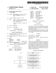
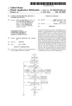
US006785579B2
(12) United States Patent
(10) Patent N0.:
(45) Date of Patent:
Huang et al.
(54)
(56)
SYSTEM AND METHOD FOR CREATING A
CONTROLLING DEVICE
US 6,785,579 B2
Aug. 31, 2004
References Cited
U.S. PATENT DOCUMENTS
(75) Inventors: Steve Lan-Ping Huang, Placentia, CA
(US); Kim-Thoa Thi Nguyen, Yorba
4,866,434 A
Linda, CA (US); Han-Sheng Yuh,
*
9/1989
Keenan ............... .. 340/825.72
5,909,183 A * 6/1999 Borgstahl et a1. .... .. 340/825.22
6,127,941 A * 10/2000 Van RyZin ........... .. 340/82569
6,608,638 B1 * 8/2003 Kodosky et al. .......... .. 345/771
Walnut, CA (US); J ianJ un Cao,
Cypress, CA (US); My Thien Do,
Anaheim, CA (US)
* cited by examiner
(73) Assignee: Universal Electronics Inc., Cypress,
CA (US)
(*)
Notice:
Primary Examiner—Anthony Knight
Subject to any disclaimer, the term of this
patent is extended or adjusted under 35
Assistant Examiner—Thomas Pham
(74) Attorney, Agent, or Firm—Gary R. Jarosik
U.S.C. 154(b) by 0 days.
(57)
(21) Appl. No.: 10/463,153
Jun. 17, 2003
(22) Filed:
Prior Publication Data
(65)
A system and method for creating a controlling device. In
response to a user specifying one or more operating criteria
for the controlling device, the system selects executable
instructions from a library of executable instructions and
command code sets from a library of command code sets
that are to be stored in the memory of the controlling device.
In addition, the system uses the criteria to suggest command
US 2003/0233664 A1 Dec. 18, 2003
Related US. Application Data
(63)
Continuation of application No. 09/716,888, ?led on Nov.
20, 2000, now Pat. No. 6,640,144.
(51)
(52)
Int. Cl.7 .............................................. .. G05B 19/18
key/command code mappings for use Within the controlling
device. The user may interact With the system to modify the
selected executable instructions, command code sets, and
command key/command code mappings. When stored in the
memory of the controlling device, the executable instruc
US. Cl. ............................. .. 700/65; 700/2; 700/66;
700/83; 700/84; 359/148; 379/102.01; 379/102.02;
379/102.03; 341/23; 345/171; 345/172;
345/158; 345/740; 345/741; 345/2.1; 345/2.3;
345/168; 345/169
(58)
ABSTRACT
tions are to be used to perform various operations and
functions Within the controlling device and the command
codes are to be transmitted from the controlling device to
command the operation of controllable devices in response
Field of Search .............................. .. 700/65, 2, 66,
to activation of one or more of the command keys.
700/83, 84; 359/148; 379/102.01, 102.02,
102.03; 341/23; 345/171—172, 158, 740,
12 Claims, 9 Drawing Sheets
741, 2.1, 2.3, 168—169
Slept: Project setup
1. Assign Project Name
2. Choose Project directory
MEXr
CHOOSE
E:and otHER
cmp Size Slll?ion:
a
HiqhiEnd or téw-EM
smsmsmu,
32k
Chip §le/Modsl:
1 msuamsx)
2. 1424 team)
5, 1532 ‘6.2m.
32K)
Step3: um Key:
Choose Phystcnl Modes (up
to 5 modes)
NEXT
BACK
mp4; Lnglcol Devices
mg" logical devices \0
mm
Availnbll Made Names:
U.S. Patent
Aug. 31, 2004
US 6,785,579 B2
Sheet 1 0f 9
Start
l
Create New Project
l
Step1: Project Setup
1. Assign Project Name
2. Choose Project directory
NEXT
BACK
Y
Step2: Market and Platform
CHOOSE
A
Chip Size/Model:
Market Selection:
USA, EURO, ASIA
A
_
Product_Type
Selection:
T
Chip size Sekaction;
8K,15K,16k,24k,
1_ 1O16(8K,15K)
2_ 1424(16K24K)
and OTHER
High-End or Low-End
32k
3‘ 1532(162’4K
32K)
NEXT
BACK
’
Step3: Mode Keys
Available Mode Names:
Choose Physical Modes (up
52%’ gagl‘éuyvmwggb
to 8 modes)
VIDEO, DVD, AUX.
NEXT
BACK
<-—_—_-
Step4: Logical Devices
Available Device Group:
TV, CABLE. VCR, and CD.
Assign logicol devices to i‘_—_
-_—__->
mode
More Modes
to assign?
NEXT STEP
FIG. I
U.S. Patent
Aug. 31, 2004
<23
US 6,785,579 B2
Sheet 2 0f 9
NEXT
BACK to Step4
Step:5 Load Coverage
<————
—————Pl
1. Select Market Coverage
Load Coverage: 5%—99%
for each device type or use
of each Market
user load.
2. Select Default Mode.
l NEXT
Step6: Key Selections
. Select physical function
keys.
———-—-——>
Function Assignment
ASSIGN
—>
2. Check selected
physical
.
E3: to assign Secondary DONE
Pick functions to physical
keys for each device type.
1 NEXT
BACK
‘—
Step7: Feature Selections
-—_—-——-—>
Available Optional Features:
Key Mover,
Macros,
Rotating Macros,
EEPROM Selection:
Optional Feature
NONE, 128 Bytes, 512
Selections: Select desired
Bytes, lK Bytes, 2K
features for the product.
Bytes
l NEXT
‘BACK
Step8: Build
l. Configure Key Matrix for
PCR.
2. Build Project Image.
Channel Scan,
Fav. Channel Scan,
Upgrade,
Learner,
Modem,
Back Light,
Mopde Light,
ID Lock,
UEI Sleep,
Double REC Key,
User Reset,
Video Lock,
Shift 1 time,
Shift Lock,
Dedicated Keys,
Dedicated Device,
Factory Test,
Channel Control Lock,
CH +/— Simulation Lock.
HAS ERROR
FIG. 2
U.S. Patent
Aug. 31, 2004
Sheet 3 0f 9
US 6,785,579 B2
@
Increase
Project Loud?
Reduce Project Size:
Increase Project Size:
Go Back to Previous Steps
Go Buck to Previous Steps
or Remove ID Loud.
or Add ID Load.
BACK to
REMOVE IDs
Previous Steps
DONE
DONE
ID Selector
Add/Remove Individual Ids from
each device type.
BACK
<-————
Step9: ?nish
Display Project Con?guration.
FINISH
DONE
FIG. 3
<——_———
U.S. Patent
Aug. 31, 2004
Sheet 4 0f 9
US 6,785,579 B2
@] Project Setup 1E2] Market and PlotfurmTETl Mode Keys TEQ Logical Devices T
Load Co
Get Started with the UEls Fully Automated System Tool(FAST)
Welcome to FAST! Please follow the steps to customize your new product,
Please give a name for your new product:
| RELAY
|
Please choose a directory for this Project:
lc:\PR0JEcTsl
l |
(Note: a new directory will be created under this
path with the name of the product.)
Nextl>
FIG. 4
W Project Setup
[E] Market and PlotformTlE] Mode Keys
Logical Devices
Laad
Product Target Market
—Which region is the target market?
O USA
O EUR ’
O ASIA
O OTHER
— Pleose choose the Product Type
C) Hi-End Product
0 Low-End Product
— Please select the Chip Family and for this product:
—01016 Chip —————
01424 Chip
OaK
O 15K
[ OisK
O 24K
—01532 Chip
O32K-44 QFP
O 24K-44 QFP
O 16K-44 QFP
032K-32 SOP
O 24Ki32 SOP
O l6K-32 SOP
<l§ack
FIG. 5
?extb
U.S. Patent
Aug. 31, 2004
@1 Project Setup
Sheet 5 0f 9
US 6,785,579 B2
Market and PlatformTiiéipjI Mode Keys
Logical Devices
Load
Mode Key Setup
Please assign physical Mode Keys for the product
Suggested Modes
Assigned Mode Keys
CABLE
TV
VCR
00
SAT
AMP
TUN
AUDIO
VIDEO
DVD
AUX
@
<l
ll >
Double-click to modify Mode name
Hints: Drag-Drop to Add/Remove Mode
Key. Hold Ctrl key to select multiple
@
FIG. 6
lm Project Setup
Market and PlatformTlEl Mode Keys
Logical Devices
El Load
Assign Device Type to Mode Keys
Please select the types for each mode key:
-Choose Group to select individual types:—
6) CABLE Group
0 TV Group
0 VIDEO Group
0 AUDIO Group
— Mode Key:
Name: [E
Default ID:
c0005
Change
Cable Converter (0 MODE)
‘E
‘l
l
1*
Wdeo Accessories (N MODE)
Satellite Receivers (S MODE)
‘l
Rule: Each Mode Key must have device types
assigned from the same group and cannot have
l
l>
Click "Next" to set up next Mode
device types from multiple groups.
IE]
FIG. 7
U.S. Patent
Aug. 31, 2004
[@ Project Setup
Sheet 6 0f 9
US 6,785,579 B2
Market and PlatformTw Mode Keys
Logical Devices
Lood Col
ID Morket Coverage Selection
Please select the market coverage percentage for each device type
I‘
Market
99%
%
- Note:
1. To select different ID’s coverage percentage
double click the Percentage column for o
Drop-Down box
99%
2. Only one Dedicated Device is allowed and the
device will only contain its default ID
99%
3. Click “Load User ID List" button to import your
99%
ID load.
looted Mode'l' 1.1
99
‘Default Mode
This is the mode the remote control will default
°
to upon power-on,
99%
4
P
Click to load ID list9 Load User ID List
@E
FIG. 8
[EI Market and Plutformm?l Mode KeysTiiTLlil Logical Devicesn?fii Load CoverageTiEJ Key Selection
Physical Key Selection
Please select keys for the product. The selected keys will be the physical keys on the remote
Available Keys
Selected Physical Keys
Key Label
iOutron Name A
KIA/5' BYPASS
A/B
[EA KEY
AKY
KlALL LIGHTS OFF
lKlALL LIGHT ON
ALF
ALN
@AM
AMK
iKlANGLE
KIANTENNA
IEARM
ANG
ANT
ARM
IKIASPECT
ASP
|__K_\AUTO TRACK
ATK
IKIAUDIO
AUD
[KIAUX
AUX
‘l
—
Key Label
IOutron Narne ‘
l] IKIVOLUMN Keys
vL#
—'
B IKICHANNEL Keys CH#
[1 IE POWER
U EENTER
PWR
RECALL
'
Z
l
l>
Hold Ctrl to select multiple keys.
-'
<l
'
‘
L
l
l>
Check boxes to assign secondary (shifted) keys.
lSetup Outronsl i<i§ack| iNextDi
FIG. 9
U.S. Patent
Aug. 31, 2004
Sheet 9 0f 9
US 6,785,579 B2
Keyboard Matrix Setting
Key Code and Switches Assignment
Key Lists
INPUT ——>
O
\
Auto Assign
IXI
l
2
3
4
5
6
7
3 olsAT l|ov0
ITD 1|sEruPl IEJT
‘TJZIPWR llREW
IK’IvL+ ll
||c0
llpwu
llUPP
ll
|[0P4
lloPs
llDP6
llDP7
HAUX
IIEXT
llTUN
llAMP
|lcLR
jlRHT
ll
II
|l0s|lRPT
ll
II
]|Ds+
]|sEL
ll
ll
l
]
l
l
V 4|vL- HFFP HDP1 Hops |\Au01o]|
ll
It
I
5|CH+ HSTP [[DP2 ||DP9 ||vmEo|l
6lCH- llPAU llDPB IIDPO ll ll
7lMUT llREC ll ll ll ll
||
ll
ll
H
II
ll
I
I
l
Drag and Drop a key to assign keyscan code.
|I|
Cancel
Note:
1. "Auto Assign” will automatically assign keys from the "Key Lists” to empty
key boxes.
2. Drag a key from the list or a box and drop it to the box you want to. If there is
a key in the box already, both keys will be swapped.
FIG. l3
US 6,785,579 B2
1
2
SYSTEM AND METHOD FOR CREATING A
CONTROLLING DEVICE
siZe of the memory Within the controlling device, and/or the
processor chip Within the controlling device.
From the speci?ed criteria, the system Will select execut
This application is a continuation of and claims the
bene?t of US. Application Ser. No. 09/716,888, ?led Nov.
20, 2000, now US. Pat. No. 6,640,144.
able instructions from a library of executable instructions
and command code sets from a library of command code sets
that are to be stored in the memory of the controlling device.
In addition, the system Will suggest command key/command
BACKGROUND OF THE INVENTION
code mappings for use Within the controlling device. The
user may interact With the system to modify the selected
This invention relates generally to controlling devices
and, more particularly, relates to a system and method for
10
creating a controlling device such as a universal remote
executable instructions, command code sets, and command
key/command code mappings. When stored in the memory
control.
Controlling devices are knoWn in the art. For example,
US. Pat. No. 5,689,353 discloses a universal remote control
Which can be coupled via coded signals With a receiver built
into various types of consumer appliances. In this manner,
of the controlling device, the executable instructions are to
be used to perform various operations and functions Within
the universal remote control can be used to transmit a
response to activation of one or more of the command keys.
command code signal to the consumer appliances to control
the operation of the consumer appliance(s) that are adapted
to respond to the command code signal.
For controlling the operation of the different types of
consumer appliances, a command code library is stored in
the memory of the controlling device. As Will be
appreciated, a command code library is required since
different consumer appliances and/or consumer appliances
A better understanding of the objects, advantages,
features, properties and relationships of the invention Will be
the controlling device and the command codes are to be
transmitted from the controlling device to command the
operation of different types of controllable devices in
20
principles of the invention may be employed.
25
manufactured by different manufacturers typically have dif
(i.e., commands for commanding the operations of a given
BRIEF DESCRIPTION OF THE DRAWINGS
For a better understanding of the invention, reference may
be had to a preferred embodiment shoWn in the folloWing
ferent coding formats by Which the command codes are
transmitted. Within the command code library, the command
codes that are transmitted using a common coding format
obtained from the folloWing detailed description and accom
panying draWings Which set forth an illustrative embodiment
and Which are indicative of the various Ways in Which the
draWings in Which:
30
type of consumer appliance of a given consumer appliance
manufacturer) are grouped into a command code set.
FIGS. 1—3 illustrate a flow chart diagram of an exemplary
method by Which a controlling device can be created;
FIG. 4 illustrates an exemplary screen shot by Which a
user can designate a project name for the controlling device
It is also knoWn in the art to store executable instructions
to be created in accordance With the method illustrated in
in the memory of a controlling device for use in controlling 35 FIGS. 1—3;
the operation and features of the controlling device. By Way
FIG. 5 illustrates an exemplary screen shot of a graphical
of example, US. Pat. Nos. 5,959,751 and 6,014,092 disclose
user interface (GUI) by Which the user selects criteria for
a universal remote control having executable instructions
creating the controlling device in accordance With the
that alloW a user to assign one or more command codes to
a selected key. In accordance With this described feature,
activation of the selected key Will cause the controlling
method illustrated in FIGS. 1—3;
40
device to transmit to the consumer appliances the command
code(s) that have been assigned to the selected key.
Presently, creating a controlling device is a time consum
ing and, therefore, costly endeavor. In this regard, creating
45
a controlling device requires the manual selection of the
command codes and programming of the executable instruc
FIG. 8 illustrates an exemplary screen shot of a GUI by
device. It is also requires that the layout of the intended
create a controlling device that adequately balances the
needs of an end user against the development cost of the
50
55
appliance types and speci?es a poWer-on default for the
operating modes of the controlling device to be created in
accordance With the method illustrated in FIGS. 1—3;
Which the user selects the physical keys for the controlling
device to be created in accordance With the method illus
trated in FIGS. 1—3;
SUMMARY OF THE INVENTION
FIG. 10 illustrates an exemplary screen shot of a GUI by
60
Which the user maps the physical keys to functions in
accordance With the method illustrated in FIGS. 1—3;
65
Which the user selects features to be supported by the
executable instructions to be included in the controlling
device to be created in accordance With the method illus
trated in FIGS. 1—3;
FIG. 11 illustrates an exemplary screen shot of a GUI by
By Way of example, operating criteria may include the
intended market for the controlling device, the intended end
use of the controlling device, the types of devices the
controlling device is intended to control, the functions
intended to be supported Within the controlling device, the
Which the user selects a market coverage for the consumer
FIG. 9 illustrates an exemplary screen shot of a GUI by
controlling device.
To overcome this disadvantage, the subject invention
provides a system and method for creating a controlling
device. The controlling device is created by a user specify
ing one or more operating criteria for the controlling device.
FIG. 7 illustrates an exemplary screen shot of a GUI by
Which the user selects consumer appliance types for the
operating modes of the controlling device to be created in
accordance With the method illustrated in FIGS. 1—3;
tions that are to be stored in the memory of the controlling
keyboard for the controlling device be manually created
keeping in mind the proposed command code library and
features to be supported by the controlling device. Manually
performing these tasks suffers the disadvantage of failing to
FIG. 6 illustrates an exemplary screen shot of a GUI by
Which the user selects the operating modes of the controlling
device to be created in accordance With the method illus
trated in FIGS. 1—3;
FIG. 12 illustrates an exemplary screen shot of a GUI by
Which the user can edit the individual command code sets to
US 6,785,579 B2
3
4
be included in the controlling device to be created in
accordance With the method illustrated in FIGS. 1—3; and
for controlling the operation of a plurality of different
consumer appliances for a plurality of different manufactur
ers and executable instructions by Which the operation and
features of a controlling device may be controlled. The hard
FIG. 13 illustrates an exemplary screen shot of a GUI by
Which the user can edit key code and sWitch assignments in
accordance With the method illustrated in FIGS. 1—3.
disk, magnetic disk, and optical disk have associated drives
that are connected to the system bus by a hard disk drive
interface, a magnetic disk drive interface, and an optical disk
DETAILED DESCRIPTION
Turning noW to the ?gures, Wherein like reference numer
als refer to like elements, there is illustrated a system and
method for creating a controlling device. The system and
drive interface, respectively.
To create a controlling device, as illustrated in FIGS. 1—3,
10
instructions to be selected from the database for storage in
the memory of the controlling device as Well as select the
method may be used to establish a command code library,
executable instructions Which implement speci?c features,
and keyboard layout for the controlling device. Generally,
the command code library, features, and keyboard layout are
established as a function of the intended end use of the
the user Will cause certain command codes and executable
desired processor chip, memory, and keyboard layout for the
15
controlling device. To gain access to the computer and the
database, a user may ?rst be required to log-in to the
computer by providing a recogniZed ID and passWord. Once
controlling device as Well as the processor type and memory
a user has gained access to the computer, the computer
siZe to be included in the controlling device.
The command code library comprises a plurality of com
mand codes, grouped in command code sets, that may be
transmitted from the controlling device, in response to
activation of a command key, to remotely control the opera
preferably prompts the user for a project name. The project
tion of one or more consumer appliances. Consumer appli
For use in the process of creating the controlling device,
the computer prompts the user for information pertaining to
name may include, by Way of example, a ?le name and a ?le
directory. In this manner, the project can be stored and, in the
future, accessed and/or edited as desired. An example of a
prompting screen is illustrated in FIG. 4.
ances that are especially adapted for remote control include
TVs, VCRs, DVD players, thermostats, fans, entry systems,
25
and other like home appliances. The features of the control
ling device, such as favorite key setup, macro key setup, etc.,
are performed in accordance With executable instructions
that are used to control the operation of the controlling
device itself. The command code library and executable
instructions are stored in the memory (e.g., RAM, ROM,
controlling device to be created. The initial information
requested of the user may include, but is not limited to, the
desired target market region, the desired product type, and
the desired processor chip to be included in the controlling
device, as seen in the exemplary screen shot of FIG. 5. The
EEPROM) associated With the controlling device. Examples
of controlling devices include universal remote controls,
personal digital assistants (PDAs), expanded-function cel
lular telephones and home computers. As Will be understood
by those of ordinary skill in the art, the command codes that
comprise the command code library may be transmitted
from the controlling device to the consumer appliances by
35
40
invention is performed in connection With a computer that is
under the control of computer executable instructions. The
computer need not be limited to a personal computer but
may include hand-held devices, multiprocessor systems,
45
microprocessor-based or programmable consumer
electronics, minicomputers, mainframe computers, and the
like. The computer executable instructions may include
routines, programs, objects, components, and/or data struc
tures that perform particular tasks. While described in the
consumer appliances typically found in the United States/
North America. The selection of the target market may also
be used by the computer to provide an initial suggested
mapping of command codes to command keys that Will be
placed on the controlling device.
The selection by the user of a loW-end or high-end product
is also used by the computer to select a subset of executable
instructions from the database corresponding to a typical
feature set for that class of product, for possible storage in
the memory of the controlling device. This selection may
also be used by the computer to provide an initial suggested
mapping of command codes to command keys. The desig
context of a single computer, the computer executable
nation of a loW-end device versus a high-end device merely
refers to the intended end use of the controlling device. As
Will be appreciated, the intended end use of the controlling
device has an impact on the number of features and com
instructions may be distributed among a plurality of com
puters connected via a netWork, such as the Internet.
For performing the tasks in accordance With the computer
executable instructions, the computer includes a display, a
processing unit, a system memory, and a system bus that
selection of a target market region, e.g., USA, Europe, or
Asia, is used by the computer to select a subset of the
plurality of the command codes stored in the database for
possible inclusion in the command code library that is to be
placed into the memory of the controlling device. By Way of
example, selection by the user of “USA” as a target market
Will cause the computer to select those command codes from
the database that are used to control the operation of
any suitable Wired or Wireless transmission means such as
IR, radio frequency (RF), or the like.
More speci?cally, the method that is the subject of the
the intended end use and desired characteristics of the
55
mand code/command key sets that the controlling device is
expected to support. By Way of example, a high-end device
(e.g., a remote control to be used in connection With a home
couples the system memory to the processing unit. Amouse,
keyboard, touch pad, joy stick, or like type of input device
theater) Would be expected to have command code/
command key sets for commanding the performance of a
greater number of operations by the consumer appliances
may be used to enter information into the computer. The
system memory may include computer-readable media such
as a ROM and/or RAM. The computer-readable media may
and support more features than Would a loW-end device
also include a hard disk, a magnetic disk, and/or an optical
(e.g., a remote control to be packed in the box of a cheap
disk. The computer-readable media provides non-volatile
storage of the computer executable instructions, data
television).
structures, program modules and other data needed to oper
ate the computer. In addition, the computer-readable media
provides a database that has a plurality of command codes
65
While the memory selected by the user Will in?uence the
amount of information that may be stored in the controlling
device, the type of processor chip selected by the user for use
in the controlling device Will also in?uence Which features
US 6,785,579 B2
5
6
the computer may select for inclusion in the controlling
device. For example, if the chip selected by the user has a
QFP pin layout (having 44 pins), the controlling device can
the model number/manufacturer of the consumer appliance
that the command code set corresponding to the ID number
is intended to control. For reasons that Will be explained in
support a mode LED feature. If, hoWever, the chip selected
by the user has a SOP pin layout (having 32 pins), the
sets Within a group be arranged in a sequential order based
greater detail beloW, it is also preferred that command code
controlling device cannot support a mode LED feature since
the SOP chip Will have an insuf?cient number of I/O pins to
control the operation of the LEDs needed to support the
mode LED feature. As Will be understood, the mode LED
upon the descending popularity of the consumer appliances
feature is used to ?ash/illuminate a LED on the controlling
preferred embodiment, this order is maintained via a sepa
rate cross-reference to permit adjustments to be made from
time to time as popularity changes. This additionally alloWs
separate lists to be maintained for each market, since a given
command code set may not enjoy equal popularity in every
intended to be controlled by each command code set. Such
popularity order may be determined from installed base
data, consumer surveys, sales statistics, or the like. In a
device to provide a user With an indication of the current
mode of operation of the controlling device. Thus, in the
case of a selected SOP processor chip, the computer Will not
permit selection for inclusion in the memory of the control
ling device those executable instructions needed to imple
ment the mode LED feature.
15
When a sequential assignment of ID numbers to com
mand code sets Within a device type group is used, types of
For determining Which modes of operation the controlling
consumer appliances Within a single group can be selected
device Will support, the user is prompted to select one or
more modes from a displayed list of available modes for the
for inclusion under a single physical mode key Without
creating an ambiguity. HoWever, since the selection of types
controlling device. As Will be appreciated by those of skill
in the art, the placing of the controlling device into a
of consumer appliances from different device type groups
can create problems in the set-up mode of the controlling
device, the computer should prevent users from placing
device types from different groups under a single mode key
particular mode causes the controlling device to access
designated command code sets from the command code
library stored in the memory of the controlling device. The
controlling device may be placed into a particular mode in
geographical region.
25
during the controlling device creation process. For example,
response to the activation of a mode key placed on the
the computer should not alloW a user to mix TVs and audio
keyboard of the controlling device. To select Which physical
mode keys the controlling device Will support, as illustrated
devices under a single “TV” mode key as it is likely that both
in the exemplary screen shot of FIG. 6, the user can either
set having a common ID number (e.g., “123”) such that the
the TV group and the audio group Will have a command code
drag a mode from the “suggested modes” list and drop the
inclusion of both under the “TV” mode Would result in a
mode to the “assigned mode keys” list or select one or more
controlling device that Would not being able to reconcile the
entry of the common ID number during the TV mode set-up
of the modes in the “suggested modes” list and click on the
“add” button.
Once the user has selected Which physical mode keys the
device Will include, the user then selects Which types of
process.
35
consumer appliances Will be capable of being controlled
When a particular physical mode key is activated. By Way of
example, and as illustrated in the screen shot of FIG. 7, the
controlling device can be con?gured such that it Will access
the command code set(s) in its memory that are capable of
40
commanding the operation of a cable converter, video
accessory, and/or satellite receiver When the “cable” mode
of product in each mode that the user previously selected. By
key is activated.
The types of consumer appliances that may be assigned to
mode keys are preferably divided into consumer appliance
type groups. Examples of consumer appliance type groups
include a cable device type group, TV device type group,
audio device type group, and video device type group. For
Way of example, if the user selects 95% for consumer
appliances of the type TV, the user is requesting that the
45
computer include enough command code sets in the com
mand code library such that 95 out of every 100 TV sets
currently in use by consumers in the selected target market
region (e.g., USA) Would be expected to be operable using
the controlling device. For use in this process, the database
also maintains an approximate percentage of the installed
base of the consumer appliances that a given command code
example, cable boxes, satellite boxes, and video accessories
can be classi?ed as belonging to the “cable” group and laser
disc players, DVD players and VCRs can be classi?ed as
set is expected to operationally control.
To arrive at the command code library that has the desired
market coverage, the command code library is initially
belonging to the “video” group.
In keeping With the designated groupings, each command
code set that is used to control the operation of the types of
consumer appliances that form a group is assigned a unique
To ?nish the initial process of selecting the command
codes that are to be included in the command code library,
the user is prompted to select a desired market coverage. An
exemplary screen shot of an appropriate prompt is illustrated
in FIG. 8. The market coverage is the percentage of the
installed base of a type of consumer appliance that the
controlling device is expected to support. The user is
expected to select a desired market coverage for each type
55
set up code, or “ID number.” These ID numbers are main
tained in the database and, When a command code set is
created With the command code sets from the database that
are capable of commanding the operation of the consumer
appliances of the selected type(s) Within the selected market
region. This command code library is then pared doWn to
stored in the memory of the controlling device, the ID
number corresponding to that command code set is also
provided to the controlling device. In this manner, as Will be
appreciated by those of skill in the art, the ID number
arrive at the selected percentage of coverage for the selected
device type(s). Speci?cally, command code sets are elimi
nated from the command code library for each device type
assigned to a command code set can be input by a user of a
in a descending order as a function of their assigned popu
controlling device to set-up the controlling device to com
mand the operation of a preferred consumer appliance When
larity (i.e., by eliminating the command codes correspond
ing to less popular devices).
the corresponding mode of operation is active. Typically, for
use in setting up the controlling device, the user is provided,
in a user’s manual or the like, With a list of ID numbers and
65
If the user has manually edited the list of command codes
as Will be described in more detail later, overriding the
automatic selection process, the user Will be noti?ed, for
US 6,785,579 B2
7
8
example, by highlighting an consumer appliance type ?eld.
function of Whether the device Was designated to be a
In this manner, the user Will be informed that a manual
high-end or a loW-end device. Once the physical keys have
been de?ned as described above, activation of the “setup
selection of command code sets for inclusion/exclusion in
the command code library is in effect. The manual selection
of command code sets may be intermixed With the auto
mated method described above, With some device types
outrons” icons Will take the user to the setup outrons screen,
an example of Which is illustrated in FIG. 10. An outron is
a tag that is assigned to a physical key—e.g. “FFD” for the
physical key Which is to be labeled “Fast ForWard”, or
“PWR” for the physical key that is to be labeled “Power”,
on the completed remote control. (It Will be appreciated that
con?gured manually and others automatically. It is also
possible for an explicit user-provided list of ID numbers to
be used to create the command code library, via the “load
user ID list” icon shoWn in FIG. 8
10
When establishing the market coverage for types of
consumer appliances capable of being commanded by the
controlling device, a user may also select that a particular
consumer appliance type is to have a dedicated command
code set. To this end, the user may selected that that desired
type of device is to be operated in the dedicated mode. In
connection With this selection, the user Will designate one,
on the ?nal remote control product these labels may take the
form of shapes or icons in place of alphanumerics, such as
“>>” for “Fast ForWard”.) The outron tags are used to
associate each physical key With its speci?c command
unchangeable command code set, preferably by its assigned
function for each of the consumer appliance types selected
by the user, in the manner described beloW.
To set-up the outrons, the user Will interact With the
computer to assign or map device functions (i.e., acts to be
performed in response to the receipt of a command code) to
ID number, for inclusion in the command code library for
the physical keys previously designated for the controlling
the given type of device. For example, if the controlling
device is to be shipped With a speci?c product (e.g., VCR),
the command code library for the mode corresponding to the
type of device may be con?gured to include only the
command code set(s) that control the operation of the
speci?c product. In this manner, a dedicated VCR, universal
15
20
device. To this end, the database preferably has a pre
con?gured mapping for each device type given the criteria
selected by the user (e.g., high-end/loW-end and USA/Asia/
Europe). The pre-con?gured mapping is displayed to the
user in an the initial outron set-up screen. The user may opt
25
to use the suggested mapping or may move/delete device
TV and universal cable box command code library for a
functions using, for example, standard drag and drop GUI
controlling device can be created by the computer.
techniques.
More speci?cally, the illustration of FIG. 10 depicts
physical keys con?gured for the controlling device in the left
For designating Which type of device(s) the controlling
device Will be con?gured to control When it is ?rst poWered
up, the user may also be provided With the ability to select
a default mode and default command code set for each
hand column With the command functions currently
assigned to each key for each device type selected by the
device type in the selected modes. The selection of a default
mode may be made using the screen shoWn in FIG. 8
user. The column on the extreme right shoWs the additional
command functions still available but not assigned for the
30
(VIDEO in the example shoWn) and default command code
set(s) for each mode may be made using the screen shoWn
in FIG. 7 (Cable mode default to device ID C0003 in the
example shoWn). If the user does not designate a command
35
“A” and drag them over to the “available but unselected”
code set to be used as the default command code set for the
device type(s) in the selected modes, the command code set
that has the highest popularity should be used as the default
command code set for the device type(s). This default
con?guration of the controlling device may be altered by a
40
comprise the command code library. It Will be appreciated
that, upon completion of this process, the command code
library created by the computer Will include command code
sets capable of commanding the operation of consumer
into the noW blank spaces to map these functions to the
selected keys.
45
may require a function that is so critical to the use of that
consumer appliance that, for that device ID only, the func
50
tion should be available someWhere on the keypad even if a
physical key does not exist for it. For this purpose, the screen
displayed to the user can display a drop doWn list, or the like,
by Which the user can select a device, by its device ID
number, to place the screen in a mode by Which the user can
55
In addition to creating the command code library, the user
is also guided through steps for creating the keyboard to be
included With the controlling device. To this end, the user is
presented With a screen, an example of Which is illustrated
assign functions to command keys for that device.
Yet another desirable feature is the ability to assign
“shifted”, or alternate, functions to certain keys. A “shifted”
function on a remote control is accessed by the user pressing
a “shift” key immediately prior to the function key, causing
in FIG. 9, by Which the user can drag and drop, select and
add, etc. the desired physical keys from an “available key”
list to a “selected physical key” list. When the controlling
device is to be a universal remote control, it is preferred that
some physical keys be pre-selected and in the “selected
60
physical key” list, e.g., digit keys, volume keys, channel
65
keys and a poWer key. The “available key” list may include
all possible keys or may be limited by the computer as a
The ability to interactively assign functions to command
keys on a device ID by device ID basis is also desirable. For
example, a particular model or brand of consumer appliance
appliances of speci?ed types typically used in a speci?ed
region With a selected, approximate percentage of market
coverage for the consumer appliances Within the speci?ed
region.
list. This action leaves keys DPO through DP9 blank in the
“A” column (i.e., no functions assigned thereto). The user
can then select input sWitching functions from the pool of
available functions (e.g., “CD” and “TAPE”) and drag them
user through commonly knoWn set-up procedures.
Once the above-described process is completed for all of
the selected types of consumer appliances in all of the
selected modes, the command codes that meet the various
criteria entered by the user Will be those command codes that
device type selected (in the example, the “A” or ampli?er
device type). By Way of further example, a designer Who
Wants to change the ampli?er device to support input selects
in place of digit keys can grab DPO through DP9 in column
the function key in question to transmit an alternative IR
command code, for example the “>>” key for a CD player
may send a “track skip” command in the regular mode and
a “disk skip” command in the “shifted” mode. This feature
alloWs extra functions to be offered on a remote control
While still retaining a reasonable total number of keys. In an
alternative implementation, the user presses the “shift” key
together With the function key rather than immediately prior
US 6,785,579 B2
10
to it, however the effect is the same. Referring again to FIG.
FAVORITE CHANNEL SCAN—feature by Which a user
can pre-program the unit With his favorite channels
9, during the physical key selection process any keys Which
are to support shifted functions are designated via a click
Which can then be scanned through.
ID LOCK—feature primarily used in OEM or Cable
markets. AlloWs a particular device code (eg a speci?c
model cable box) to be set up at the factory or by the
installer and locked in, so the end user cannot change
the set up for that speci?c mode.
able check box in the Selected Physical Key table. In the
speci?c example shoWn, the Fast ForWard, ReWind, Play,
Stop, Pause, and Record keys are so designated. Referring
noW to FIG. 10, it Will be noted that these key labels are
repeated at the end of the Outron Assignment table (shaded)
to alloW suitable secondary functions to be assigned to them.
After the user has completed the mapping of functions to
command keys, signi?ed to the computer by the user click
ing on the “con?rm” icon, the user is prompted to indicate
Which features are desirable to be included in the controlling
device. As illustrated in FIG. 11, selection of the features
may be accomplished by interacting With check boxes or the
10
KEYMOVER—feature Whereby a key on the keypad can
be reassigned to send a different code.
LEARNING—feature by Which a remote can be “taught”
like displayed to the user. The computer may cause certain 15
features to be pre-selected as a function of the criteria
previously established for the device (e.g., high-end/loW
SHIFT—feature by Which one or more keys can be
assigned a secondary command code.
SLEEP—feature by Which the remote emulates a “sleep”
command by sending “PoWer Off” after a set interval.
Interval is selected by user in 15 minute increments by
remote control to match the customer’s devices. Using
the keypad, the user enters an ID code corresponding to
the brand and model for each device type supported by
the operating modes of the remote.
repeated presses of the key.
Mode Mover—feature Whereby a mode key can be reas
signed to a different device type than its default. For
example, a user With no cable box but tWo VCRs might
The selection by the user of a feature Will cause the
computer to select from the database for storing in the
memory of the controlling device the executable instructions
Want to reassign the “cable” mode key to place the
needed by the controlling device to perform the selected
remote in a second “VCR” mode.
feature.
Audio Lock—feature Whereby a speci?c device is desig
In connection With selecting the features desired to be
nated as the master audio control across modes of
included in the controlling device, the user may choose to
35
optimiZe printed circuit board layout and mechanical design.
40
codes can be searched and used to determine if a
consumer appliance.
Master Reset—feature Whereby the remote control can be
45 device. At this time, the user can also command the com
puter to build the command code library, executable instruc
tions needed to operate the controlling device and perform
the selected features, the device IDs, and the command
code/command key maps that have been created by the
above-described processes Which Will be stored in the
memory of the controlling device.
During the build, the computer may provide an indication
processor chip and memory chip selectable by the user (e.g.,
the mode LED feature or certain features that require an
EEPROM). In addition, since some features are related to
other features, the computer Will select related features
automatically for the user (e.g., a product should have the
as to an estimated memory utiliZation, or “load” that Would
result from storing the build on the selected chip(s). If the
55 load on the memory is too great, the user may elect to
include a larger memory in the controlling device and/or
elect to remove certain command code sets and/or features
from the build. If the memory has load to spare, the user can
elect to add command code sets and/or add features to the
build. In this case, the user may also elect to reduce the
amount of memory in the controlling device. The user can
but are not limited to:
CHANNEL SCAN—feature Whereby pressing a special
“SCAN” key starts the remote sending “Channel Up”
once every 3 seconds, until any other key is pressed.
MACRO—feature Whereby a command key on remote
can be programmed to cause the sending of one or more
command codes.
To this end, the user can be presented With a key matrix
display, an example of Which is shoWn in FIG. 13, by Which
the user can drag and drop the previously selected physical
keys to arrange the location of the physical keys on the
printed circuit board Which Will form part of the controlling
command code set is appropriate for operating a given
“channel scan” feature if the “favorite channel scan” feature
is selected). Certain of the features Will ask the user to set up
the mode keys and/or group of keys a feature should be
locked to. In this regard, locking means that the function or
operation mapped to a command key Will operate across all
or some of the modes of the controlling device. Examples of
features that may be included in a controlling device include,
con?gure the physical keyboard matrix. Although the com
puter automatically assigns a physical crosspoint in the key
matrix to every key selected as part of the process described
in connection With FIG. 9, it is sometimes desirable to assign
speci?c keys to particular locations in the matrix in order
matter Which of the modes the remote is in.
Blink Back—feature Whereby a LED blinks the device ID
number to Which the remote is currently set.
returned to its default operating mode.
With respect to the optional features that may be added to
the remote control, certain of the check boxes related to the
features may be disabled by the computer based upon the
the button he Wants it to learn.
any digit key (i.e. selecting the channel desired).
limited to:
Direct Set-up—feature Whereby the user may set up a
Library Search—feature Whereby the library of command
a neW key function by the user, usually by placing his
original unit close to the learning remote and pressing
POWER TOGGLE—feature by Which the “PoWer” key
only turns poWer off. PoWer is turned on by pressing
end). Preferably, all default features are pre-selected for all
products. Examples of default features include, but are not
operation, such as TV, VCR, and Cable. The remote
Will alWays send that device’s volume command codes
in response to activation of audio command keys no
ILLUMINATED KEYPAD—feature for controlling key
pad illumination.
65
effect this by returning to any of the steps previously
described in conjunction With FIGS. 5 through 11 iteratively,
or by customiZing the load by adding or removing command
code sets to the build, by device ID, for the various modes
to be included in the controlling device as is illustrated by
Way of example in FIG. 12.
US 6,785,579 B2
11
12
When the build is complete, the build may be downloaded
to the memory of a controlling device, having the desired
2. The method as recited in claim 1, Wherein the command
codes selected are appropriate for commanding devices
microprocessor, memory and keyboard matriX, to thereby
Within a geographic region.
3. The method as recited in claim 1, Wherein the command
code library and features for the intended end use of the 5 codes selected cover an install base of a type of consumer
provide a controlling device having the desired command
appliance.
controlling device. Thus, it Will be appreciated that the
4. The method as recited in claim 1, Wherein the build
described system and method alloWs a designer to interac
further comprises instructions for operating the controlling
tively make tradeoffs betWeen chip siZe, features, coverage,
number of keys, etc. during the design of a controlling
device. Furthermore, the resultant eXecutable instructions
10
and command code library are built from an “erector set” of
standardiZed, pretested, and prequali?ed modules With little
or no human intervention or programming required, thereby
greatly improving the reliability of the ?nal product While
simultaneously reducing development and testing time. In
device.
5. The method as recited in claim 1, Wherein the build
further comprises a mapping betWeen keys of the remote
control and command codes.
6. The method as recited in claim 1, Wherein the build
further comprises identi?ers Which are assigned to prede
15
this manner, the described system and method alloWs a
controlling device to be created that is best suited for its
termined subsets of the selected command codes.
7. The method as recited in claim 1, comprising accepting
input via the user interface for mapping command codes to
command keys of the controlling device.
intended end use While being developed With a savings in
8. The method as recited in claim 7, comprising accepting
input via the user interface for con?guring a layout of the
both time and cost.
command keys.
All patents discussed in this document are hereby incor
porated by reference in their entirety.
9. The method as recited in claim 8, Wherein the user
While speci?c embodiments of the invention have been
described in detail, it Will be appreciated by those skilled in
interface provides drag and drop capabilities.
the art that various modi?cations and alternatives to those
interface to access instructions for use in creating a control
details could be developed in light of the overall teachings
10. A method for using a netWork enabled computing
25
of the disclosure. For example, the processes described With
respect to computer eXecutable instructions can be per
controllable devices Whereby command code sets from
formed in hardWare Without departing from the spirit of the
a library of command code sets that are remote from the
invention. Accordingly, the particular arrangement disclosed
controlling device and Which are appropriate for com
is meant to be illustrative only and not limiting as to the
scope of the invention Which is to be given the full breadth
manding operations of the plurality of different con
trollable devices are selected by the instructions as a
of the appended claims and any equivalents thereof.
function of the input for inclusion into a build adapted
to be doWnloaded into the memory of the controlling
What is claimed is:
1. A method for creating a controlling device having a
memory, comprising:
35
accepting via a user interface input that functions to
specify a plurality of different controllable devices
devices are selected as a function of the input for
inclusion into a build adapted to be doWnloaded into
the memory of the controlling device;
displaying via the user interface an estimated memory
utiliZation of the build;
displaying via the user interface an option Which is
selectable to enable modi?cation of Which command
code sets are included in the build to thereby modify the
estimated memory utiliZation of the build; and
displaying via the user interface an option Which is
selectable to cause doWnloading of the build for inclu
sion into the memory of the controlling device.
device;
displaying via the netWork enabled user interface an
estimated memory utiliZation for the build as deter
mined by the instructions;
Whereby command code sets from a library of com
mand code sets that are remote from the controlling
device and Which are appropriate for commanding
operations of the plurality of different controllable
ling device having a memory, comprising:
accepting via the netWork enabled computing interface
input that functions to specify a plurality of different
displaying via the netWork enabled user interface an
40
option Which is selectable to enable modi?cation of
Which command code sets are included in the build to
thereby modify the estimated memory utiliZation of the
build; and
displaying via the netWork enabled user interface an
option Which is selectable to cause doWnloading of the
build for inclusion into the memory of the controlling
device.
11. The method as in claim 10, Wherein the netWork
enabled computing interface comprises a graphical user
interface.
12. The method as in claim 11, Wherein the user interface
is located remotely from the instructions.
*
*
*
*
*


![AGIVEN PROGRAM ]](http://vs1.manualzilla.com/store/data/005708142_1-ae1c6d6b32e7a9016e2dede042b38772-150x150.png)