1
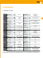
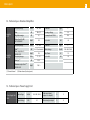
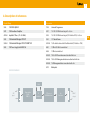
Ref. 563501 EN DVBS2-QAM CI User manual w w w. t e l e v e s . c o m DVBS2-QAM CI Contents Technical specifications . ..................................................................................................................... References’ descriptions ..................................................................................................................... Mounting . ............................................................................................................................................ 3.1. Wall mounting ............................................................................................................................... 3.2. 19” rack mounting ....................................................................................................................... Elements’ descriptions ........................................................................................................................ 4.1. Introduction................................................................................................................................. 4.1. DVBS2-QAM CI.......................................................................................................................... 4.2. Power supply unit ...................................................................................................................... 4.3. Amplification options ............................................................................................................... 4.4. Universal programmer .............................................................................................................. How to use the product ....................................................................................................................... 5.1. Standard Menu ......................................................................................................................... 5.2. Extended menu . ........................................................................................................................ 5.3. Saving of parameters . .............................................................................................................. 6. Controlling the device ............................................................................................................... Example of application. Distribution of 7 DVB S2 channel in QAM format ......................................... Rackmount standards ......................................................................................................................... Standards for mounting cabinets ........................................................................................................ 5 7 8 8 9 10 10 11 12 13 14 15 15 17 18 19 20 21 23 EN ENGLISH 1. 2. 3. 4. 5. 7. 8. 9. 5 1. Technical specifications 1.1. DVBS2-QAM CI ref. 5635601 Satellite Demodulator Input Frequency MHz 950 - 2150 Input Modulation Input Level dBµV dBm 49 to 84 -60 to -25 Symbol Rate Frequency Steps MHz 1 type “F” female ohm 75 Input and Output connectors Input impedance Mbaud 10-30 Mbaud (QPSK- 8PSK) FEC Inner code LDPC LDPC (9/10, 8/9, 5/6, 4/5, 3/4, 2/3, 3/5, 1/2, 1/4, 1/3, 2/5) FEC Outer code BCH Bose-Chaudhuri-Hocquenghem % 20, 25, 35 dB 10 Roll-off Factor LNB power&tone control Vdc/KHz 13-17- OFF / 22KHz (ON-OFF) Return losses (min.) Through Losses dB Modulation Format QAM Modulator Symbol Rate max. Roll-off Factor UP-Converter Scrambling Mbaud 6,9 Interleaving % 15 Bandwidth (max.) Reed Solomon (188, 204) Spectral inversion Output Frequency MHz 46- 862 (selectable) Frequency Steps KHz 250 Phase Noise typ. dBc/Hz 90 (@10KHz) Output Level General < 1,5 16, 32, 64, 128, 256 QAM Block Code DVB-S2 (QPSK, 8PSK) DVB-S (QPSK) DVB ET300429 DVB ET300429 MHz 8 Normal / Inverted (selectable) Through losses dB < 1,5 Return losses dB > 12 Input and Output connectors type “F” female. dBµV 80 ±5 (selectable) Output Impedance ohm 75 Adjustable Output Level dB >15 (selectable) Spurious level (typ.) dBc > 60 (55 min.) Powering Vdc 24 IP 20 Consumption at 24V mA 550 (without powering LNB) 800 (powering LNB) Index of Protection: The technical characteristics described are defined for a maximum ambient temperature of 45°C (113ºF). Forced ventilation must be used for higher temperatures. EN DVBS2-QAM CI 6 1.2. Technical specs. Broaband Amplifiers Frequency range Amplifier 5575 Amplifier 451202 MHz 46 ... 862 Connector type Gain dB 44 ± 2,5 Powering voltage Vdc 24 Regulation margin dB 20 Consumption at 24 Vdc mA 450 Output level (60 dB) 42 CH CENELEC dBµV 105 Test socket dB -30 Frequency range (1) MHz 47 ... 862 Gain (1) Max. output level (1) DIN 45004B Frequency range (2) dB 40 - 53 (selectable) Gain typ. (2) Maximum output level DIN 45004B (1) Forward channel (2) Connector Mains voltage “F” type “F” Vac/Hz 196 - 264 / 50-60 dBµV 129 Max. Power W 16 MHz 5 ... 30 Test socket dB -20 dB 20/ -3 dBµV 129/ --- (2) Return channel (active/passive) 1.3. Technical specs. Power Supply Unit Power Supply Unit 5629 Mains voltage Vac/Hz 196 - 264 / 50-60 Output voltage Vdc 24 Total current (max) (outpur 1 + output 2) A 5 Max current per output A 4 7 2. Description of references Product Range Accessories 5630 T.0X DVBS2-QAM CI 7234 Universal Programmer 5575 T.0X Broadband Amplifier 5071 T03-T05-T.0X Wall mounting rail L=50 cm 451202 Amplifier DTKom (47 - 862 MHz) 5239 T03-T05-T.0X Wall mounting rail (12 Modules+PSU) L=56 cm 5559 T.0X Headend Manager CDC-IP 5301 19” Subrack frame 555901 T.0X Headend Manager CDC-IP GSM T-0X 507202 T.0X Lockable cabinet with Ventilation Unit (7 Modules + PSU) 5629 T.0X Power Supply Unit 24VDC/5A 4061 75 Ohm DC-Block terminal load 4058 75 Ohm terminal load 422601 T05 to T.0X Power interconnection lead L=40 cm 422602 T05 to T.0X Management interconnection lead L=40 cm 422603 T.0X Management interconnection lead L=1m 5673 Blank plate BLOCKS DIAGRAM CAM SAT input Demodulator DVB-S DVB-S2 CI Interface TS Processor QAM Modulator Up Converter DVB-C output EN DVBS2-QAM CI 8 3. Mounting 3.1. Wall mounting 563501 5629 5575 5071 5239 QAM output 4061 7234 NOTE: The use of both PSU power outputs is recommended to balance the consumption. For example, 4+3 or 3+4 9 3.2. 19” rack mounting EN DVBS2-QAM CI 10 4. Elements’ descriptions 4.1. Introduction The DVB project has brought about an evolution in DVB-S/S2 satellite transmission standards in order to improve its characteristics, with the objective of increasing satellite transponder capacity and flexibility in transporting different types of data beyond the MPEG transport stream. To do this, new coding schemes and more complex modulation schemes are used (8PSK). For error protection, it has progressed from the DVB-S Viterbi and Reed Solomon scheme to more complex algorithms (LDPC and BCH). Furthermore, DVB has established the QAM modulation format as one of the digital signal distribution formats in SMATV networks, characterised by its robustness against noise and adjustment errors as well as its high spectral efficiency. According to this standard, TV signals via satellite are distributed across SMATV networks using transparent transmodulators, which convert the satellite modulation format to QAM. Furthermore, it is also possible to carry out transmodulation of terrestrial digital television signals (COFDM) to QAM. The unification of the modulation format to QAM for signal distribution allows the user to utilize a unique, receiver for all signal types, independently of their original modulation format (DVB-S, DVB-S2 or COFDM). “Stuffing” In many cases, QAM receivers include software that performs frequency band searching with only one symbol rate as a variable, for example 6.875 or 6.9 Mbaud, which is the maximum binary rate that can be sent over an 8 MHz channel for QAM modulation. Therefore, transmodulation devices that are installed in the headend must operate at this symbol rate, independently of the input signal’s binary rate. To achieve these QAM signal characteristics, DVB TS packet stuffing should be performed in the headend. This complicates automatic searching or “scanning”: the receiver should detect all QAM distribution signals by searching the entire band, using both frequency and binary rate as searching parameters. This process can be very slow. Automatic searching is easier if all QAM signals are identical (same modulation format and symbol rate). As a result, stuffing techniques are applied to demodulated data prior to their subsequent QAM modulations. Service Elimination In some cases, especially with DVBS2 input signals, the satellite input rate may be too high to be transmitted in a QAM output signal. It is necessary to select which of the services available at the input will be distributed at the output, eliminating unwanted services and thus reducing the binary rate. PID_filtering At the same time, for certain distributions such as small CATV, the network operator may decide to eliminate certain services (PID_filtering) in order to avoid paying royalties to the service provider. The DVB-S2 to QAM transmodulator allows the selection of available services at the input for elimination at the output. This fact causes that some scanned void services are identify by the receiver as N.A. (for example). Operator_id For certain cable networks, it is important to replace the operator_id field received in the input transport stream with a value corresponding to the cable network operator. This action is managed by the CDC software, version 2.14 or higher. NIT Handling To make easier the receiver’s search for all available QAM signals on the SMATV network, a mechanism for processing the NIT table (NIT Handling) has been implemented. It consists of generating a NIT table that contains all the information from different QAM channels present on the network (frequency, modulation order, baud rate). Each transmodulation module, DVBS2-QAM substitutes the NIT table at the input for this new table. This way, the receiver only needs to tune in to a QAM channel in order to access this data, greatly facilitating the search for services currently on the network. The user manages this NIT Handling mechanism via the CDC connectors on the top of its front, in order to enable the passage of the input signal to other modules. 11 4.2. DVB S2 - QAM CI EN 1. 2. 3. 4. 5. SAT IF input SAT IF output RF input RF output Powering input The DVBS2 to QAM transmodulator with CI receives a satellite transponder, in any of DVBS (QPSK) or DVBS2 (QPSK or 8PSK) modulation formats, and demodulates it to obtain a DVB TS package.Then, the DVB TS transport package is modulated in QAM format and converted to the output channel 6. 7. 8. 9. Status LED Control BUS connector CAM slot PC/Programmer socket (UHF or VHF and with a maximum bandwidth of 8 MHz) using an agile up-converter. Additionally, it incorporates a Common Interface slot for inserting a conditional access module (CAM) that permits the unscrambling of services. Insert the smartcard completely into the CAM slot. Card contacts looking left and forwards when it is being inserted. Programming of the transmodulator operating parameters (input frequency, output channel, modulation format and adaptation of services mainly) is performed by means of the universal programmer (ref. 7234). DVBS2-QAM CI 12 4.3. Power supply unit (1) Connectors to power the modules (1) GND On LED 24V: OK 0V: Overload or short circuit Mains input 230V~ NOTES: - The power source can supply a maximum of seven TWIN DVBS2-QAM modules. - Whenever the demand of power exceeds 4A (max. current for each output), it is necessary to distribute it between the two powering outputs of the PSU. 13 4.4. Amplification options OPTION “A” - Amplifier ref. 5575 OPTION “B” - Amplifier ref. 451202 EN 1. 2. 3. 4. RF output Test output RF input 1 RF input 2 5. 6. 7. Powering input Status LED Attenuator It features two input connectors, to allow mixing of channels coming out from two different systems. If only one of the inputs is used, it is recommended to load the unused input with a 75 ohm terminator, ref 4061. As the rest of T.0X units, this amplifier is powered via the 24 Vdc power BUS. Input signals through connectors 3 & 4 are combined and amplified in the frequency band 47-862 MHz 1. 2. 3. 4. 5. 6. 7. Mains input (196- 64 V~ 50/60 Hz) Ground terminal ON/OFF LED MATV input / Return channel output MATV input test MATV output test MATV output / Return channel input Broadband amplifier in shielded zamak chassis, with gain configured by the installer. DVBS2-QAM CI 14 4.5. Universal Programmer The programmer features 4 buttons: (short press) - Selection of parameter (positioning of the cursor). - Modification of the parameter chosen by the cursor (flashing) (short press) - Change menu (long press) - Change between Principal and Extended menus (long press) - Save changes to memory + Cloning menu. + + Increases the contrast of the screen. + + Decreases the contrast of the screen. 15 5. - How to use the product 5.1. Standard Menu 5.1.b. QAM Modulation Menu Connect the controller to the front socket of the module (“PRGM”). At first, the controller’s firmware version will appear: 5.1.a. Input Menu The following main menu displays the selected QAM modulation parameters: Next, it is displayed the firmware version of the DVBS2-QAM CI module : The first main menu allows selection of input frequency, the symbol rate, and the LNB powering (0, 13 V-22KHz, 13 V, 17 V-22KHz, 17 V) To modify the frequency, press until the cursor shifts over the desired digit. Then change its value using keys and . The range of allowed input frequency values is 950-2150 MHz, whereas the range for symbol rate is 10 to 30 Mbaud for DVB-S2 signals and 2 to 42.5 Mbaud for DVB-S signals. In the event that there is a “short circuit” in the input connector (LNB powering enabled), the LED will flash on the front of the module until the condition disappears. EN • The available options for this menu as well as their possible values are: 16QAM, 32QAM, 64QAM, 128QAM and 256QAM. • The IQ parameter is the modulation format selection and can be set to “normal” or “inversion”. • The user must select the QAM output baud rate, which can be set up to a maximum of 6.69 MBaud. Note The bandwidth required depends on the number of services present on the output (those selected as ON or DCY, see menu of services). DVBS2-QAM CI 5.1.c. Output Menu The next main menu shows the frequency or output channel, the output off set (only in channel mode), the level control and the selection of output spectrum inversion. 16 channel from the table selected as well as the offset regarding the channel’s receiving point frequency. The permitted off set values depend on the frequency diff erence selected (see confi guration menu): • Steps of 125KHz: ±4 (-500, -375, -250, -125, 0, 125, 250, 375, 500 KHz) • Steps of 166KHz: ±3 (-500, -333, -166, 0 , 166, 333, 500 KHz). 5.1.d. Service Menu To change the frequency press the key until the desired parameter flashes. This fi eld can be then be changed by means of the keys ▲ and ▼ . In frequency mode you can select any output frequency value between 177.5 - 226.5 MHz (VHF) and 474 - 858 MHz (UHF). The decimal part depends on the difference of frequency chosen (see extended menu 5.2). If you select a difference of 125 KHz the permitted values for the decimal part are 0, 125, 250, 375, 500, 625, 750 and 875 KHz. With a difference of 166 KHz the possible values are 0, 166, 333, 500, 666 and 833 KHz. The output level control permits values between 00 and 99. The possible values for the spectral inversion are “Norm.” (not inverted) and ‘Inv.’ (spectrum inversion). In channel mode it lets you select an output This menu shows the list of transport stream services at the input. Each time the user selects a new input transport stream, the unit performs a search for services. During the process, the unit will show the message below displaying the number of channels as soon as they are being found: Once the search has completed, a list of services is displayed with the following information: number of services in the multiplex (the figure shows service 2 out of 8 services), the statistics (18/25), the name of the service and if the user has selected it to: a) be removed from the output (OFF), or b) pass through without modification (ON). The statistics information is structured as follows: N / M, where: N: p ercentage of the output occupied by the service indicated. M: p ercentage of output which is free. In the example displayed, France 2 will occupy the 18% of the output (it is in OFF and therefore it is being eliminated) and there is a 25% of free room. Thereby it can be seen that this service can be activated (set to ON) since there is enough room for it at the output. The percentage free at the output only is updated if the configuration of services is saved. Additionally, on the upper right corner of the window it is indicated the status of the service (encoded or plain) at the input for the services ON and DCY: Service encoded at the input and at the output. Service encoded at the input and plain at the output. Service encoded at the input. The service order number as well as the total 5.1.e. Measurements Menu 1 17 This menu shows an indication of the quality of the input by means of an estimation of the C/N (dB) as well as of the link margin (dB). When the key is held down for more than 3 seconds the unit displays a series of menus that are used less frequently, called extended menus. 5.2.. Configuration Menu f. Measurements menu 2 This menu enables the address of the unit to be selected (to be controlled through a CDC Headend Control). It also allows selection of the output frequency difference (125 or 166KHz), the table of channels to use or frequency mode operation. This menu indicates the occupancy rate of the module’s output as well as the maximum achieved. If too many services are selected it will result in an output overfl ow and this condition is indicated. 5.2.b. Identifiers Menu Some DVB-C receivers may have problems receiving transmodulator channels that share the same identifier (stream_transport_id). To avoid these cases, the user is allowed to change the following identifiers of the DVB-C multiplex of the output: • transport_stream_id (TS_ id) • network_id (n_id) • original_network_id (on_id). You can choose between Auto (the identifiers are not changed) or Manual mode. By switching to manual mode, the identifiers received from the satellite are shown and thus the user can change them. The available tables of channels that can be selected are the following: Occupancy values higher than 82% are not recommended. This is a read only menu, which disables the keys ▲ and ▼. You can reset the the maximum occupation by pressing the key . 5.2. Extended Menu • • • • • • • • • • CCIR China Chile Italy France OIRT channels Ireland Southafrica Poland Australia 5.2.c. Temperature Measurement Menu The following menu indicates the unit’s current temperature as well as the maximum recorded. It is possible to reset the maximum by pressing the key. EN DVBS2-QAM CI 18 e. User’s CAM (MMI) interface menu This last extended menu allows the selection of menu languages (Spanish / English / German): This menu allows access to the user interface of the CAM (Conditional Access Module), for example, to check versions or rights of the card: The recommended operational margins are as follows: • Optimum Operation : 0-6 By pressing the keys ▲ and ▼, you change the selected language. • High Temperature: 7-8 • Excessive Temperature: 9-10 If the maximum recorded is outside the optimum margin, the installation should be revised in an attempt to reduce the temperature. If the DVBS2-QAM CI modules have been installed in a housing ref. 5069 and the temperature of one of the modules is outside of the optimal operating range, the ventilation unit will have to be installed ref. 5334. To check whether this change is eff ective the maximum can be reset and its value checked after a given time. 5.2.f. LNC (Logical Channel Number) Menu This menu lets you assign a LCN (Logical Channel Number), between 1 and 1023, to the services that are present at the output (those marked ON or DCY). 5.3. Saving of parameters Once the desired value has been selected in any of the menus (normal or extended), in order to save the information, hold down the key for approximately 3 seconds. The screen will display the following: 5.2.d. Version Menu This menu displays the firmware versions for the unit as well as the one of the QAM modulaor (FPGA). To change the LCN, make use of keys , and ▲ or ▼. If you select 0000 as the LCN, it will show “NO LCN.” 5.2.g. Language Menu Do not remove the programmer until the message disappears. If you change the configuration data, but these have not been recorded, the previous settings are restored after 30 sec of elapsed time, ie, the changes are canceled. 19 6. - Controlling the Device This version of the DVBS2-QAM CI allows configuration and monitoring via a PC, both locally and remotely. EN 6.a. Local control The “Headend Management” programme (v2.14 or higher) is required, as well as a special lead (provided with the programme) that connects a PC serial port to the “PRGM” socket of the DVBS2-QAM CI module. The programme can be used to set up and read all the operating parameters, as well as to monitor the correct operation of the device. 6.b. Remote control It is necessary to have a Headend Control module (ref. 555901) that includes the programme mentioned above, and the corresponding modem connected to a phone line. Once the communication with the headend control has been established, all the controllable devices that have been installed in the headend can be accessed. In this case it is imperative that each module is programmed with a different device address selected between 1 and 254. At any moment, modules A and B can be switched by pressing keys ▲ and ▼ when the cursor is over the A/B indication situated on the upper left corner. DVBS2-QAM CI 20 7. Application example Distribution of 7 DVB S2 satellite channels in QAM format. 75 ohm 4061 5629 5629 7 x 5630 (14 canales) 451202 7 x 563501 7 QAM channels The diagram shows the reception and processing of 7 DVB S2 channels to be distributed as QAM channels. At any situation, the limitation of 4 A per output of the PSU must be kept in mind. QAM Output 21 8. Rackmount Standards (max. 49 DVBS2-QAM CI - 7 subracks with 5U height - 8,7”) 8.1. Installation of the rack with ventilation facilities To facilitate the renewal and circulation of the air inside the rack, in order to reduce the temperature of the units and improving their performances, it is advisable to place 2 ventilation units of 25W, particularly when the rack with the DVBS2QAM CI is located in warm places, with ambient temperatures higher than 45°C. These ventilators will be installed on a tray that is fixed on top of the cabinet (fig. 1 & 2). This way, the fans are forcing circulate the cool air that enters through the base of the cabinet between the modules, which is expelled through slots on top of the cabinet (3-5 cm approx.). See fig. 3. EN Frontal Subrack fig. 1 fig. 2 fig. 3 DVBS2-QAM CI 22 8.2. I nstallation of the rack without ventilation facilities It is very important that this process operates correctly, therefore the following must be observed: - Do not open the side doors, as this would cause the ventilators to extract the air from the outside rather than the air inside the rack. To install the units in racks without installation facilities, and when the rack is located in places with temperatures around 45°C, it is advisable to place the rack completely open; in other words, do not use the side doors. This is to facilitate the ventilation of the units , fig. 5. - Do not place objects near the rack that could clog the ventilation inlets and outlets. - If the rack is not complete, the subracks must be placed from the top downwards without leaving any gaps in between, fig. 4. fig. 4 fig. 5 23 9. Standards for mounting cabinets IMPORTANT The scheme of recommended ventilation is the one shown in the figure, for any way of placement of the cabinet (horizontal or vertical). EXTRACTOR for forced ventilation. Must be located higher than the top module. EN Maximum environment temperature: 45ºC. Around the cabinet located higher, the maximum temperature permitted is 45ºC, either for cabinets placed horizontally or vertically. Horizontal placement Vertical placement The lower grid may be located on any wall DVBS2-QAM CI 24 IMPORTANT Horizontal placement of cabinets is strongly recommended by fixing them as near as possible to the floor . HORIZONTAL If the horizontal placement is impossible, then vertical placement is allowed. Respect the recommended minimum distances in the attached schemes. Install the cabinet as low as possible Maximum T: 45ºC. VERTICAL 25 Guarantee Televés S.A. offers a two year guarantee, beginning from the date of purchase for countries in the EU. For countries that are not part of the EU, the legal guarantee that is in force at the time of purchase is applied. Keep the purchase invoice to determine this date. During the guarantee period, Televés S.A. complies with the guarantee by repairing or substituting the faulty equipment. The harm produced by improper usage, wear and tear, manipulation by a third party, catastrophes or any other cause beyond the control of Televés S.A. is not included in the guarantee. EN DVBS2-QAM CI 26