1
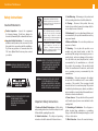
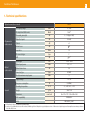
Ref. 234901 EN Optical Fiber Dual Return Path Receiver User manual w w w. t e l e v e s . c o m Dual Return Path Receiver Index Technical specifications . ..................................................................................................................... Ordering information . .......................................................................................................................... Mounting . ............................................................................................................................................ 3.1. 19” rack mounting ....................................................................................................................... Product description ............................................................................................................................. Tables for gain installations calculation ............................................................................................... 6 7 8 8 9 10 EN ENGLISH 1. 2. 3. 4. 5. Dual Return Path Receiver Safety instructions: Caution Statements roduct inspection - Inspect the equipment P for shipping damage. Should any damage be discovered, immediately file a claim with the carrier. I mportant Safety Instructions - To ensure proper installation and operation, take a moment to read this guide before proceeding with the installation. If you have any questions or comments about the T.0X Series Optical Fiber Receivers please contact your dealer. WARNING: TO PREVENT FIRE OR ELECTRICAL SHOCK DO NOT EXPOSE TO RAIN OR MOISTURE. 4 A product and cart combination should be moved with care. Quick stops, excessive force and uneven surfaces may cause the product and cart combination to overturn. The lightning flash with arrow head symbol, within an equilateral triangle, is intended to alert the user to the presence of uninsulated “dangerous voltage” within the product’s enclosure that may be of sufficient magnitude to constitute a risk of electric shock to persons. The exclamation point within an equilateral triangle is intended to alert the user to the presence of important operating and maintenance (servicing) instructions in the literature accompanying the product. WARNING: TO REDUCE THE RISK OF FIRE OR ELECTRIC SHOCK, DO NOT EXPOSE THIS PRODUCT TO RAIN OR MOISTURE. DO NOT OPEN THE CABINET, REFER SERVICING TO QUALIFIED PERSONNEL ONLY. CAUTION:TO PREVENT ELECTRIC SHOCK, DO NOT USE THIS (POLARIZED) PLUG WITH AN EXTENSION CORD RECEPTACLE OR OTHER OUTLET UNLESS THE BLADES CAN BE FULLY INSERTED TO PREVENT BLADE EXPOSURE. CAUTION:TO REDUCE THE RISK OF ELECTRIC SHOCK, DO NOT REMOVE COVER. NO USER-SERVICEABLE PARTS INSIDE. REFER SERVICING TO QUALIFIED PERSONNEL. Important Safety Instructions 1. Read and Follow All Instructions - All the safety and operating instructions should be read prior to and followed while operating this product. 2. Retain Instructions - The safety and operating instructions should be retained for future reference. 3. Heed Warnings - All warnings on the product and in the operating instructions should be adhered to 4. Cleaning - Disconnect this product from any electrical source before cleaning. Use a damp cloth; do not use liquid or aerosol cleaners. 5. Attachments - Do not use attachments that are not recommended by the product manufacturer as they may cause hazards. 6. Water and Moisture - Do not use this product near any source of water. 7. Mounting – Do not place this product on an unstable cart, stand, tripod, bracket, or table. The product may fall, causing serious injury to persons or nearby objects, and serious damage to this product. Use only with a cart, stand, tripod, bracket, or table recommended by the manufacturer, or sold with the product. Any mounting of the product should follow the manufacturer’s instructions, and should use a mounting accessory recommended by the manufacturer. 8. Ventilation – Slots and openings in the cabinet are provided for ventilation and to ensure reliable operation of the product. These openings should never be blocked or covered in any way. This product should not be placed in any case, cabinet, or rack unless proper ventilation is provided and the manufacturer’s instructions have been adhered to. 9. Power Sources - This product should be operated only from the type of power source indicated on the marking label. 10. Grounding or Polarization - Do not bypass or defeat electrical plug polarization or grounding. Doing so will violate the warranty and may pose a risk of fire or electrocution. 11. Wire Protection – Ensure all connected wiring is 5 routed correctly to avoid damage including pinching, excessive bends, or compression. 12. Electrical Supply, Grounding, and Surge Protection – Ensure that all local or national electrical codes are followed. Seek the advice of a licensed electrician, professional engineer, or other licensed expert. See example wiring figure. 13. Power Lines - Always use caution and avoid operating this or any connected equipment near uninsulated power line or any other hazards. 14. Object and Liquid Entry - Never allow objects or liquid of any kind into this product through openings. Doing so could result in fire or electric shock. 15. Servicing – There are no user serviceable parts. Do not attempt to service this product or remove covers. Doing so may expose you to dangerous voltage or other hazards. Refer all servicing to qualified service personnel. Examples of damage requiring service include but are not limited to: - Damage to power-supply wiring. - If liquid has been spilled, or objects have fallen into the product. - If the product has been exposed to rain or water. - If the product does not operate normally by following the operating instructions. Adjust only those controls that are covered by the operating instructions as an improper adjustment of other controls may result in damage and will often require extensive work by a qualified technician to restore the product to its normal operation. - If the product has been dropped or physically damaged. - When the product exhibits a distinct change in performance. 16. Replacement Parts - Ensure that repairs are performed by qualified technicians and that only manufacturer supplied or authorized parts are used. 17. Safety Check – Upon completion of any service or repairs to this product, ensure safety checks to determine that the product is functioning per manufacturer specifications are performed. 18. Heat - The product should be situated away from heat sources such as radiators, heat registers, stoves, or other products (including amplifiers) that produce heat. Ensure that ambient temperature is maintained in the manufacturer specified operating range. Optical connection instructions: n SC/APC single mode fiber cable must be used. A Remove the protective cover from the optical connector on the unit and the cap on the cable connector. Carefully align the guides on both connectors when plugging a cable to the device, then push the connector all the way in. Take special care to avoid damaging the unprotected ends of the connectors, as small scratches, impurities and/or particles of dirt, oil, grease, sweat, etc. may significantly affect the quality of the signal. To clean the ends of the connectors, gently rub with a lint-free lens cleaning cloth, dampened using additive-free isopropyl alcohol. Make sure the alcohol evaporates fully before connecting. Keep the connector covers and cable caps in a safe place in case they are needed in the future. Always fit the covers on the connectors of devices that are not connected to cables to prevent the laser beam from damaging the eyes. Do not turn the transmitter on without a fiber optic cable connected to it. EN Dual Return Path Receiver 6 1. Technical specifications Optical receiver (two receivers) RF frequency range RF output level (AGC mode) RF parameters (each receiver) dBmV 14 ±2 (1) RF manual gain adjust dB 0 ... 14 (steps 2 dB) dB -30 ±0.5 Flatness dB ±1 Return losses dB Impedance Ohm RF connector type type dB 15 75 F 40 (2) Wavelength nm 1270 ... 1650 Optical input power dBm -16 ... +1 Optical return losses dB 50 SC/APC Connector type type Absolute maximum input power dBm 5 Supply voltage Vdc 12 ... 24 Max power consumption General 5 ... 300 Output test point NPR Optical (each receiver) 234901 MHz W 5 (24Vdc) Operating temperature ºC / ºF -5 ... +45 / +23 ... +113 Weight g / lb 900 / 1.98 mm / inch 50 x 217 x 175 / 1.96 x 8.54 x 6.88 Dimensions EMC compatibility Safety EN 50083-2 EN 60825-1_2007 (1) RF input level to 238003 is 30dBmV (return path transmitter). (2) Injection of 15 to 62 MHz block of noise with a notch at 39 MHz through 10km of fiber plus 8 way optical splitter to achieve –11dBm received optical input power. Return path laser transmitter specifications: Pout 3dBm, DFB, 1610nm. 7 2. Ordering information When ordering, please, specify reference number as per table below. Fiber Optics SMATV 233306 T.0X Optical Transmitter (1310nm/6dBm) 563701 T.0X 8PSK-QAM TWIN Transmodulator 233311 T.0X Optical Transmitter (1310nm/10dBm) 555902 T.0X CDC Headend Manager IP 233411 T.0X Optical Transmitter (1310nm/10dBm) / Return path receiver 233501 T.0X Optical Receiver 233601 T.0X Optical Receiver / Return Path Transmitter (1310nm/6dBm) 234305 T.0X Optical Transmitter (1550nm/4dBm) Accessories 234311 T.0X Optical Transmitter (1550nm/10dBm) 7234 Programming Unit 234901 T.0X Optical Dual Return Path Receiver 5301 19in Chassis (7 modules+1PSU) 2337 T.0X 2-way Optical Splitter 422603 Control BUS lead T.0X L=1 m 2339 T.0X 4-way Optical Splitter 140057 Power Bus Jumper (15 inches) 234401 T.0X 8-way Optical Splitter 234501 T.0X 16-way Optical Splitter 234601 T.0X 32-way Optical Splitter 563901 Power Supply Unit (110 Vac UL) EN Dual Return Path Receiver 8 3. Mounting 3.1. 19” rack mounting F.O. Transmitter P.S.U. DUAL RETURN PATH RECEIVER EDFA 5301 9 4. Product description With two independent receivers in the module, the 234901 return path module provides a high – density solution for advanced upstream video and data traffic. The wide optical input power range (-16dBm to 1dBm) can accommodate today´s involving networks with varying link budgets. An integrated low-noise pre-amplifier and highperformance post-amplifier offers high RF output level and exceptional distortion performance. The AGC keep the RF output level constant independently of the optical input level (-16 to 0dBm). In addition, there is a variable attenuator (0 to 14dB) to adjust the RF output level if the AGC has not been selected. EN 1.Output Test receiver 1 3.Power jack 12 ... 24V 4.LED, power OK 5.LED, optical power receiver 1 OK 6.LED, optical power receiver 2 OK 2.RF output receiver 1 LED ON Indicates Forward path optical power received. Red: RX Optical PW AGC status White: AGC is ON 7.Jack, received optical power alarm 8.SC/APC connector receiver 1 9.SC/APC connector receiver 2 10. AGC mode indicator receiver 1 11. RF attenuator control receiver 1 AGC mode ON > +1 dBm Green: -16 ... +1 dBm Orange: < -16 dBm 12. AGC mode indicator receiver 2 13. RF attenuator control receiver 2 14. RF output receiver 2 15. Output Test receiver 2 Ground +12 ... 24V Dual Return Path Receiver 10 5. T able for gain installations calculation Receiver output levels in dBmV (planning frequency: 18MHz, 28MHz, 48MHz, 58MHz and 30dBmV each channel at the input of the 238003 with return path optical power 3dBm). Optical link losses (dB) RF output power (dBmV) 6 7 8 9 10 11 12 13 14 15 16 17 18 19 48 46 44 42 40 38 36 34 32 30 28 26 24 22 Output levels given with attenuator set at 0dB. Use the attenuator if the optical link losses are less than 6dB. 11 Televes Limited Warranty (A) Televes warrants, only to the original Purchaser, all Products be free from any defect in materials or workmanship for a period of two (2) years from the date of original purchase, unless otherwise specified. (B) Televes shall, free of charge and in its sole discretion, either repair, replace with a new or factory reconditioned equivalent, or refund the purchase price of the Product(s), that has been determined by Televes to be defective in material or workmanship, subject to the limits of this warranty. (C) This warranty excludes any damage or inoperability resulting from: (I) use or installation that is not in strict compliance with the written instructions and specifications; (II) any modification or alteration performed by any third party not authorized in writing by Televes; (III) service or repair performed by any third party not authorized in writing by Televes; (IV) misuse, abuse, intentional harm, or lack of reasonable care; (V) fire, ice, snow, rain, wind, water, volcano, excessive heat or cold, lightning, flood, power surge, earthquake, or any other acts of God; (VI) war, crime, strike, riot, electro-magnetic pulse, or any other acts beyond the control of Televes; (VII) shipping. (D) All claims under the terms of this warranty must be made in writing, by the original Purchaser, within fourteen (14) days of the defect being known to the Purchaser. Such claims shall be accompanied by a description of any material facts related to the claimed defect and the invoice or other proof of original purchase date and price. If Televes so requests, the Purchaser shall, at Purchaser’s expense, deliver the claimed Product(s) to Televes, within 14 days of the date of the return authorization. Under no circumstances shall the Product(s) be returned to Televes without a return authorization. (E) Any refund to the Purchaser, shall be limited to the purchase price of the Product(s), excluding any applicable taxes, duties, freight costs, removal costs, installation costs, or any other charges incident to the purchase of the product. (F) Any damage caused by shipper shall be claimed with the shipper in accordance with the shipper’s policies and procedures. (G) Televes shall in no event and under no circumstances be liable or responsible for any consequential, indirect, incidental, punitive, direct or special damages based upon breach of warranty, breach of contract, negligence, strict tort liability or otherwise or any other legal theory, arising directly or indirectly from the sale, use, installation or failure of any product acquired by Purchaser from Televes. (H) This limited warranty extends to the original Purchaser and cannot be assigned or transferred to any other party without the prior express written permission of Televes, which permission Televes may withhold for any reason or for no reason at all. (I) Televes will not assume any liabilities for any other warranties, whether statutory, express or implied, made by any other person. (J) Televes reserves the right to modify or discontinue this warranty at Televes’ sole discretion without notification. No other warrantees are expressed or implied. EN televes.com