1
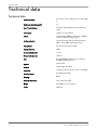
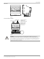
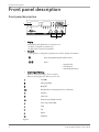
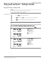
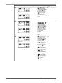
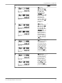
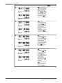
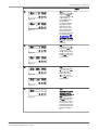
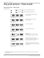
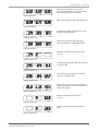
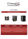
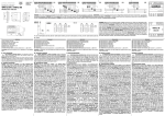
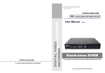
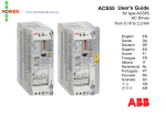
User manual
Power Analyzer PAN 311
Table of Contents
Table of Contents
Technical data.........................................................................................................................................2
Technical data......................................................................................................................................2
Front panel description......................................................................................................................... 8
Front panel description...................................................................................................................... 8
Key pad actions - Setup mode............................................................................................................. 9
Key pad actions - Setup mode...........................................................................................................9
Key pad actions - View mode............................................................................................................. 14
Key pad actions - View mode.......................................................................................................... 14
Power Analyzer PAN 311 User manual
1
Technical data
Technical data
Technical data
2
Rated input voltage:
line to neutral: 185 V to 460 V; line to line: 320 V to 800
V
Rated input current (through CT):
5A
Type of electrical system:
three phase, balanced/unbalanced load, with/without
neutral
Power supply:
24 VAC -15% +10%, 50-60 Hz
Output:
Serial port RS485, MODBUS communication, 9600 bit/s,
1 start bit, 8 data bit, no parity, 1 stop bit
Overload protection:
continuously 6 A and 120% of rated input voltage; for
500 ms: 36 A and 200% of rated input voltage
Display menus:
total 18 menus (see18-menu display)
Display refresh time:
700 ms.
Current transformer ratio:
1 to 999
Voltage transformer ratio:
1.0 to 99.9
EMC:
emission EN50084-1(residential class A); immunity
EN61000-6-2 (industrial class A)
Approval:
CE, CSA and UL
Standard:
safety En61010 – IEC-60664
Connection:
screw type; maximum cable cross section: 2.5 mm AWG
Protection degree:
front IP40; terminal IP20
Mounting:
DIN-rail
Operating temperature:
-10 to +60°C (14 to 140°F)
Weight:
about 400 g (14.1 oz) incl. packing
Part No.
40 501189
Power Analyzer PAN 311 User manual
Technical data
Dimensions
90 mm
45 mm
32.2 mm
107.5 mm
50 mm
62.1 mm
Figure 1
Connection/Electric diagram
RS-485/Modbus
Auxiliary power supply
T
2
4
18
20
Rx- TxRx+ Tx+
11 12 13 14 15
22
24
In case of connection to
a MAS Base unit,
terminals 39-40 are used.
Terminal ”T” used for
termination of the
last unit in a series of
connected units.
26 27 28 29 30 31
L1
L2
L3
Pump
Figure 2
WARNING: The current input can be connected to the line ONLY through current
transformer; the connection of the CT’s to earth MUST be carried out according to the
electric diagram shown above; when the CT is connected to earth, a leakage current from
0 to 1.8 mA max is generated depending on input impedance, connection and the line
voltage measured by the instrument.
Power Analyzer PAN 311 User manual
3
Technical data
Electrical Hazard:
EN
Electrical work must only be carried out by a qualified electrician and in accordance with
local regulations. During installation, all equipment must be disconnected from the power
supply without any possibility of being made live. Terminals 26, 27, 28, 29, 30 and 31 are
connected to voltages up to 800 V.
CS
Práce na elektrickém zařízení musí provádět pouze kvalifikovaný elektrikář podle místních
předpisů. Během instalace musí být veškeré zařízení odpojeno od napájení bez jakékoliv
možnosti, že by se mohlo dostat pod napětí. Svorky 26, 27, 28, 29, 30 a 31 jsou připojeny k
napětím až 800 V.
DA
Arbejde på elektriske installationer må kun udføres af en autoriseret elektriker og i
overensstemmelse med de lokale forskrifter. Under installationsarbejdet skal al udstyret
være koblet fra strømforsyningen uden nogen muligheder for at kunne aktiveres. Stik 26,
27, 28, 29, 30 og 31 er tilsluttet spændinger på op til 800 V.
DE
Arbeiten an der Elektrik sind ausschließlich von einem ausgebildeten Elektriker und
gemäß den geltenden Bestimmungen vorzunehmen. Während der Installation ist die
Stromversorgung zu allen Geräte zu unterbrechen und jede Möglichkeit auszuschließen,
dass diese wieder eingeschaltet wird. Anschlüsse 26, 27, 28, 29, 30 und 31 können mit
Spannungen von bis zu 800 V versorgt werden.
EL
Οι ηλεκτρολογικές εργασίες πρέπει να εκτελούνται μόνο από ειδικευμένο ηλεκτρολόγο και σύμφωνα
με τους τοπικούς κανονισμούς. Κατά τη διάρκεια της εγκατάστασης, ολόκληρος ο εξοπλισμός πρέπει
να είναι αποσυνδεδεμένος από την ηλεκτρική τροφοδοσία, χωρίς να υπάρχει το ενδεχόμενο να τεθεί
υπό τάση. Οι ακροδέκτες 26, 27, 28, 29, 30 και 31 συνδέονται σε τάσεις μέχρι και 800 V.
ES
Los trabajos eléctricos deberán encargarse exclusivamente a un electricista cualificado y
cumplir la normativa local. Durante la instalación, todo el equipo deberá permanecer
desconectado de la alimentación eléctrica de manera que sea imposible que reciba
corriente. Los bornes 26, 27, 28, 29, 30 y 31 están conectados a tensiones que pueden
llegar a 800 V.
ET
Elektritöid võib teha üksnes kvalifitseeritud elektrimontöör ning tööde teostamisel tuleb
järgida kõiki piirkonnas kehtivaid nõudeid. Paigaldamise ajaks tuleb kõik seadmed
vooluvõrgust eraldada ning igasugune võimalus nende voolu alla sattumiseks peab olema
välistatud. Klemmid 26, 27, 28, 29, 30 ja 31 ühendatakse kuni 800-voldise pingega.
FI
Sähkötyöt saa tehdä vain pätevä sähköasentaja, ja niissä on noudatettava paikallisia
määräyksiä. Asennustöiden ajaksi laitteet on aina kytkettävä irti sähköverkosta ja
huolehdittava, ettei niitä voi vahingossa kytkeä päälle. Liittimet 26, 27, 28, 29, 30 ja 31
liitetään enintään 800 V jännitteeseen.
FR
Les travaux électriques doivent exclusivement être effectués par un électricien
professionnel et conformément aux réglementations locales. Pendant l’installation,
l’ensemble de l’équipement doit être débranché de l’alimentation électrique et aucune
partie ne doit rester sous tension. Les terminaux 26, 27, 28, 29, 30 et 31 sont branchés sur
des tensions pouvant atteindre 800 V.
HU
Elektromos munkákat csak szakképzett villamos szakember végezhet, betartva a helyi
előírásokat. Telepítés során minden berendezést le kell választani az elektronos hálózatról
úgy, hogy az ne legyen visszakapcsolható. A 26, 27, 28, 29, 30 és 31 végberendezések
maximum 800 V feszültségre kapcsolódnak.
4
Power Analyzer PAN 311 User manual
Technical data
Electrical Hazard:
IT
Le connessioni elettriche vanno effettuate esclusivamente da un elettricista qualificato in
conformità alle normative locali. Durante l’installazione, tutta l’apparecchiatura va
disconnessa dall’alimentazione di rete senza alcuna possibilità che diventi sede di
potenziale elettrico. I terminali 26, 27, 28, 29, 30 e 31 sono connessi a tensioni fino ad 800
V.
LT
Elektros darbus turi atlikti tik kvalifikuotas elektrikas, laikydamasis vietinių taisyklių.
Montavimo metu visa įranga turi būti atjungta nuo srovės tiekimo; neturi būti nei
menkiausios srovės tiekimo atsinaujinimo galimybės. 26, 27, 28, 29, 30 ir 31 gnybtai
prijungiami prie iki 800 V įtampos.
LV
Tikai kvalificēts elektriķis ir tiesīgs veikt elektrības darbus atbilstoši vietējiem noteikumiem.
Uzstādīšanas laikā visam aprīkojumam jābūt atvienotam no energoapgādes, izslēdzot
jebkādu nejaušas ieslēgšanas varbūtību. Terminālu Nr. 26, 27, 28, 29, 30 un 31 pieslēdz
spriegumam līdz 800 V.
NL
Werkzaamheden aan elektrische installaties mogen alleen conform de geldende
voorschriften worden uitgevoerd door vakbekwame personen. Tijdens werkzaamheden
aan elektrische installaties moet alle apparatuur op een beveiligde wijze spanningsloos
zijn. De aansluitingen 26, 27, 28, 29, 30 en 31 zijn aangesloten op een spanning tot 800 V.
PL
Prace elektryczne muszą być wykonywane przez wykwalifikowanych elektryków zgodnie z
obowiązującymi przepisami. Podczas instalacji sprzęt musi być odłączony od źródła
zasilania, tak aby niemożliwe było wystąpienie napięcia na jakimkolwiek elemencie. Złącza
26, 27, 28, 29, 30 i 31 są podłączone do napięcia mogącego osiągać 800 V.
PT
O trabalho eléctrico deve ser realizado por um electricista qualificado em conformidade
com os regulamentos locais. Durante a instalação, todo o equipamento deve ser
desligado da fonte de alimentação eléctrica sem nenhuma hipótese de activação eléctrica.
Os terminais 26, 27, 28, 29, 30 e 31 estão ligados a tensões de 800 V no máximo.
SK
Elektrické práce môže uskutočňovať iba kvalifikovaný elektrikár, pričom v súlade s platnými
predpismi. Pri inštalácii sa všetky zariadenia musia odpojiť od napájacieho zdroja. Musí sa
vylúčiť akákoľvek možnosť pripojenia napätia. Svorky 26, 27, 28, 29, 30 a 31 sú pripojené
na napätia dosahujúce až 800 V.
SL
Električarska dela mora izvesti kvalificiran strokovnjak - električar, v skladu z lokalnimi
pravili in zahtevami. Med instalacijo morajo biti vse naprave izključene in ločene od
omrežja, ter zavarovane pred nezaželenim vklopom. Priključki 26, 27, 28, 29, 30 in 31 so
priključeni na napetost do 800 V.
SE
Elarbeten får endast utföras av en behörig elektriker och i enlighet med gällande
lagstiftning. Under installationen måste all utrustning vara bortkopplad från
strömförsörjningen och ska inte kunna göras strömförande. Uttagen 26, 27, 28, 29, 30 och
31 är anslutna till spänning på upp till 800 V.
Power Analyzer PAN 311 User manual
5
Technical data
NOTICE:
EN
Do not connect the instrument to the output side of a variable frequency drive (between
the VFD and the pump) in order to avoid malfunctioning or damage.
CS
Nepřipojujte přístroj k výstupní straně budiče s proměnným kmitočtem (mezi budič a
čerpadlo), aby nedošlo k poruše nebo poškození.
DA
For at forhindre fejl eller beskadigelse må instrumentet ikke sluttes til udgangssiden af et
variabelt frekvensdrev (mellem VFD’et og pumpen).
DE
Zur Vermeidung von Funktionsstörungen bzw. Beschädigungen darf das Gerät nicht an die
Ausgangsseite eines frequenzgestellten Antriebs (zwischen dem Mehrfrequenzmonitor
und der Pumpe) angeschlossen werden.
EL
Για την αποφυγή δυσλειτουργίας ή βλάβης, μη συνδέετε το όργανο στην πλευρά εξόδου ενός
συστήματος μετάδοσης κίνησης μεταβλητής συχνότητας (μεταξύ του VFD και της αντλίας).
ES
Para evitar que se produzcan fallos de funcionamiento o averías, no conecte el aparato en
el lado de la salida de un variador de velocidad (VFD), es decir, entre éste y la bomba.
ET
Töökindluse tagamiseks ja rikete vältimiseks ei tohi seadet ühendada reguleeritava
sagedusega ajami väljundahelasse (ajami ja pumba vahele).
FI
Älä liitä laitetta muuttuvataajuuskäytön lähtöpuolelle (käytön ja pumpun välille), jotta
järjestelmän toiminta ei häiriinny tai järjestelmä vaurioidu.
FR
Afin d’éviter tout risque de dysfonctionnement ou de dommage, ne branchez pas
l’appareil sur le côté sortie d’un système d’entraînement à fréquence variable (VFD) (entre
le VFD et la pompe).
HU
A hibás működés és károsodás elkerülése érdekében ne csatlakoztassa a készüléket a
változtatható frekvencia-szabályozó kimeneti oldalára (a VFD és a szivattyú közé).
6
Power Analyzer PAN 311 User manual
Technical data
NOTICE:
IT
Non connettere lo strumento all’uscita di un’unità a frequenza variabile (fra l’unità a
frequenza variabile e la pompa) onde evitare funzionamenti errati o danni.
LT
Nejunkite prietaiso prie kintamo dažnio pavaros išvado pusės (tarp kintamo dažnio
pavaros ir siurblio), kad išvengtumëte blogo veikimo ar pažeidimų.
LV
Ierīci nedrīkst pievienot mainīgas frekvences pievada izvades pusei (starp mainīgās
frekvences pievadu un sūkni), lai izvairītos no ierīces nepareizas darbības vai bojājumiem.
NL
Sluit het apparaat niet aan op de uitgangszijde van een aandrijving met variabele
frequentie (tussen de VFD en de pomp) omdat dit storing of schade kan veroorzaken.
PL
Aby uniknąć niewłaściwego działania lub uszkodzenia urządzenia, nie należy go podłączać
do wyjścia napędu ze zmienną częstotliwością (między napędem VFD a pompą).
PT
Não ligue o instrumento à saída de uma engrenagem motriz de frequência variável (entre
a VFD e a bomba) de forma a evitar mau funcionamento ou avaria.
SK
Nepripájajte prístroj k výstupu pohonu s frekvenčnou reguláciou (medzi VFD a čerpadlo).
Takto vylúčite riziko chybnej funkcie alebo poškodenia.
SL
Ne priključujte instrumenta na izhodno stran variabilnega frekvenčnega pogona (med VFD
in črpalko), s tem se izognete nepravilnemu delovanju ali poškodbam naprave.
SE
Anslut aldrig instrumentet till utgångssidan på en frekvensomriktare (mellan
frekvensomriktaren och pumpen) eftersom det då kan uppstå skador och funktionsfel.
Power Analyzer PAN 311 User manual
7
Front panel description
Front panel description
Front panel description
1
3
2
1.
2.
Display
LED display with alphanumeric indications to:
• display configuration parameters;
• display all the measured variables.
Key pad
To program the configuration parameters and the display of variables.
Key to enter programming and confirm selections;
Keys to:
• program values;
• select functions;
• step through view menus.
3.
Decimal point blinking
When measuring voltage: Phase to phase
When measuring power: Wrong connection
k
kilo (1000)
W
Active power (Watt)
M
Mega (106)
dmd
Displayed value is an average formed over 1 - 30 minutes
Hz
Frequency
PF
Power factor
var
Reactive power (voltampere reactive)
h
hours, used to indicate kWh
al
alarm
V
Volt
A
Ampere
VA
VoltAmpere
Figure 3
8
Power Analyzer PAN 311 User manual
Key pad actions - Setup mode
Key pad actions - Setup mode
Key pad actions - Setup mode
NOTICE:
Read the safety precautions and the specification carefully.
Connect wires according to the wiring diagram.
Key pad functions
To access Setup mode and to confirm setting value.
In Setup mode (in display: "PrG"): Scroll to the next function or increase parameter value.
In Setup mode: Scroll to the previous function or decrease parameter value.
NOTICE: To accept all changes you must enter the end parameter,see Figure 36: (page
13).
Table 1: Set the PAN311 using the key pad and go through the following steps:
Default
1.
L1
k
L2
W
M
L3
dmd Hz
PF var
dmd Hz
PF var
h
al
V
A
VA
al
V
A
VA
Figure 4
L1
k
L2
W
M
No
Press ‘S’ once, when
"A.rE" is shown, alarms
can be reset by pressing
▲ or ▼ to select
‘yes’.Confirm by pressing
‘S’.
"A.rE" = Alarm reset.
L3
h
Figure 5
2.
L1
k
L2
W
M
L3
dmd Hz
PF var
dmd Hz
PF var
h
al
V
A
VA
al
V
A
VA
Figure 6
L1
k
L2
W
M
L3
h
Press ‘S’, when "P.rE" is
shown. The Wdmd and
Amax can be reset by
using ▲ or ▼ to select
‘yes’. Confirm by
pressing ‘S’.
"P.rE" = Peak reset.
Resets the Wdmd max
and Amax.
No
Figure 7
Power Analyzer PAN 311 User manual
9
Key pad actions - Setup mode
Default
3.
L1
k
L2
W
M
L3
dmd Hz
PF var
dmd Hz
PF var
h
al
V
A
VA
al
V
A
VA
Figure 8
L1
k
L2
W
M
L3
h
0
Press ‘S’ once, when
"PAS" is shown. Enter
correct password (default
is ‘0’) using ▲ and ▼.
Confirm by pressing ‘S’.
"PAS": if you enter the
correct password you
access the setup main
menu.
Figure 9
4.
L1
k
L2
W
M
L3
dmd Hz
PF var
dmd Hz
PF var
h
al
V
A
VA
al
V
A
VA
Figure 10
L1
k
L2
W
M
L3
h
Figure 11
5.
L1
k
L2
W
M
L3
dmd Hz
PF var
dmd Hz
PF var
h
al
V
A
VA
al
V
A
VA
Figure 12
L1
k
L2
W
M
Figure 13
10
L3
h
On the first menu of the 0
setup main menu, "n_P"
(new password) is
shown. If you want to
change password, press
‘S’ to setup mode "PrG",
then use ▲ and▼ to
change value. Confirm
by pressing ‘S’.Press ▲
to go to the next
parameter.
PrG = Program (setup)
mode.
SYS" (system selection). 3P.n
If you want to change
system mode press ‘S’ to
setup mode "PrG" and
choose the correct
electrical system with ▲
and ▼. Confirm by
pressing ‘S’.Press ▲
view mode "r.03" to go
to the next parameter.
"SYS": electrical system
selection, choose the
correct electrical system.
"3P.n": 3-phase
unbalanced load with or
without neutral.
"3P.A": 3-phase ARON.
"3P": 3-phase balanced
load.
"2P": 2-phase
"1P": 1-phase
Power Analyzer PAN 311 User manual
Key pad actions - Setup mode
Default
6.
L1
k
L2
W
M
L3
dmd Hz
PF var
dmd Hz
PF var
h
al
V
A
VA
al
V
A
VA
Figure 14
L1
k
L2
W
M
L3
h
Figure 15
7.
L1
k
L2
W
M
L3
dmd Hz
PF var
dmd Hz
PF var
h
al
V
A
VA
al
V
A
VA
Figure 16
L1
k
L2
W
M
L3
h
Figure 17
8.
L1
k
L2
W
M
L3
dmd Hz
PF var
dmd Hz
PF var
h
al
V
A
VA
al
V
A
VA
Figure 18
L1
k
L2
W
M
L3
h
Figure 19
9.
L1
k
L2
W
M
L3
dmd Hz
PF var
dmd Hz
PF var
h
al
V
A
VA
al
V
A
VA
Figure 20
L1
k
L2
W
M
Figure 21
Power Analyzer PAN 311 User manual
L3
h
"Ct.r" (current
1
transformer ratio). Press
‘S’ to setup mode "PrG"
and enter value (1 – 999)
using ▲ and ▼.
Confirm by pressing
‘S’.Example: If the
primary of the CT is 300A
and the secondary is 5A,
the CT ratio is 60
(obtained from the
calculation: 300/5). Press
▲ in view mode "r.03"
to go to the next
parameter.
"Ut.r" (voltage
transformer ratio). Press
‘S’ to setup mode "PrG"
and enter value (1.0 to
99.9) using ▲ or ▼
and confirm by pressing
‘S’.Example: If the
primary of the VT is 5kV
and the secondary is
100V, the VT ratio is 50
(obtained from the
calculation: 5000/100).
Press ▲ in view mode
"r.03" to go to the next
parameter.
1
"P.i.t" (power integration 15
time), is used to calculate
‘Power dmd’ (Power
mean value). Enter time
over which the average is
formed (1 - 30 minutes)
with ▲ or ▼ in setup
mode "PrG" and confirm
by pressing ‘S’. Press ▲
in view mode "r.03" to
go to the next parameter.
"A.i.t" (Amperage
1
integration time) is used
to calculate ‘Thermical
current’. Enter time over
which the average is
formed (1 - 30 minutes)
with ▲ or ▼ in setup
mode "PrG" and confirm
by pressing ‘S’. Press ▲
in view mode "r.03" to
go to the next parameter.
11
Key pad actions - Setup mode
Default
10.
L1
k
L2
W
M
L3
dmd Hz
PF var
dmd Hz
PF var
h
al
V
A
VA
al
V
A
VA
Figure 22
L1
k
L2
W
M
L3
h
"Fi.s" (filtering range) is 2
used to set the operating
range of the digital filter
with ▲ or ▼ in setup
mode "PrG" and confirm
by pressing ‘S’. The value
is expressed as % of the
full scale value.Press ▲
in view mode "r.03" to
go to the next parameter.
Figure 23
11.
L1
k
L2
W
M
L3
dmd Hz
PF var
dmd Hz
PF var
h
al
V
A
VA
al
V
A
VA
Figure 24
L1
k
L2
W
M
L3
h
Figure 25
12.
L1
k
L2
W
M
L3
dmd Hz
PF var
dmd Hz
PF var
h
al
V
A
VA
al
V
A
VA
Figure 26
L1
k
L2
W
M
L3
h
Figure 27
13.
L1
k
L2
W
M
L3
dmd Hz
PF var
dmd Hz
PF var
h
al
V
A
VA
al
V
A
VA
Figure 28
L1
k
L2
W
M
Figure 29
12
L3
h
"Fi.c" (filtering
2
coefficient). Enter value
(1 – 16) with ▲ or ▼ in
setup mode "PrG" and
confirm with ‘S’. A higher
value increases the
stability and the settling
time of the
measurements.Press ▲
in view mode "r.03" to
go to the next parameter.
"AL.¯ " (Overvoltage:
253
Line-Neutral). Press ‘S’ to
setup mode "PrG" and
set the trip limit with ▲
or ▼. Confirm with ‘S’.
Voltage exceeding
entered value will trigger
an alarm (blinking LED:
Al).Press ▲ in view
mode "r.03" to go to the
next parameter.
207
"AL._" (Undervoltage:
Line-Neutral). Press ‘S’ to
setup mode "PrG" and
set the trip limit with ▲
or ▼. Confirm by
pressing ‘S’.Voltage
below entered value will
trigger an alarm
(blinking LED: Al).Press
▲ in view mode "r.03"
to go to the next
parameter.
Note: If Overvoltage and
Undervoltage trip limits
are the same, both
alarms are disabled.
Power Analyzer PAN 311 User manual
Key pad actions - Setup mode
Default
14.
L1
k
L2
W
M
L3
dmd Hz
PF var
dmd Hz
PF var
h
al
V
A
VA
al
V
A
VA
Figure 30
L1
k
L2
W
M
L3
h
Figure 31
"AL.n" (Overcurrent in
0.10
the Neutral). Press ‘S’ to
setup mode "PrG" and
set the trip limit with ▲
or ▼. Confirm by
pressing ‘S’. A current
through neutral
exceeding the trip limt
will trigger an alarm
(LED: Al). If the ‘AL.n’
value is 0, the neutral
current alarm function
will be disabled. The
alarm status is displayed
by a blinking LED: see
Key pad actions - View
mode (page 14), menu
5. Press ▲ in view mode
"r.03" to go to the next
parameter.
15.
L1
k
L2
W
M
L3
dmd Hz
PF var
h
al
V
A
VA
Figure 32
"Adr" (Instrument serial 255
port address). Press ‘S’ to
setup mode "PrG" and
enter value (1 – 255)
with ▲ or ▼. Confirm
with ‘S’.Press ▲ in view
mode "r.03" to go to the
next parameter.
Figure 33
16.
L1
k
L2
W
M
L3
dmd Hz
PF var
dmd Hz
PF var
dmd Hz
PF var
h
al
V
A
VA
al
V
A
VA
al
V
A
VA
Figure 34
L1
k
L2
W
M
L3
h
"E.rE" (Reset of energy
No
and hour meters). Press
‘S’ to setup mode "PrG"
and use ▲ or ▼.
Confirm by pressing
‘S’.Press ▲ in view
mode "r.03" to go to the
next parameter.
Figure 35
17.
L1
k
L2
W
M
Figure 36
Power Analyzer PAN 311 User manual
L3
h
"End".
To confirm new selected
values and leave the
setup menu, press the ‘S’
key! To remain in the
setup menu, press ▲ or
▼.Note! Being in the
Setup menu: In case no
key is pressed for 30 sec,
the display reverts to the
View mode and possible
parameter settings are
lost.
13
Key pad actions - View mode
Key pad actions - View mode
Key pad actions - View mode
Key pad functions
In View mode (in display: "r.03"): Scroll to the next displayed system variable.
In View mode (in display: "r.03"): Scroll to the next displayed system variable.
L1
k
L2
W
M
Phase voltage (phase to neutral) for each phase.
V L1-N, V L2-N, V L3-N.
L3
dmd
Hz
PF
var
h
al
V
A
VA
Figure 37: Menu 1
L1
k
L2
W
M
Phase to phase voltage. VL12, VL23, VL31.
Decimal points blink.
L3
dmd
Hz
PF
var
h
al
V
A
VA
Figure 38: Menu 2
Phase current of each phase.
L1
k
L2
W
M
L3
dmd
Hz
PF
var
h
al
V
A
VA
Figure 39: Menu 3
dmd1-value of three phase current.
L1
k
L2
W
M
L3
dmd
Hz
PF
var
h
al
V
A
VA
Figure 40: Menu 4
L1
k
L2
W
M
L3
dmd
Hz
PF
var
h
al
V
A
VA
Neutral current.
If neutral current alarm is active, "AL.n" is shown.
If neutral current alarm is not active, "n" is shown.
Figure 41: Menu 5
L1
k
L2
W
M
L3
dmd
Hz
PF
var
h
al
V
A
VA
Active power of each phase. WL1, WL2, WL3.
Decimal points blink if power is negative (generated
power, or wrong polarity connection of CT).
Figure 42: Menu 6
L1
k
L2
W
M
L3
dmd
Hz
PF
var
h
al
V
A
VA
Power factor of each phase, PF L1, PF L2, PF L3. The
example shows a power factor of 0.12, 0.16 and 0.12 for
an electric motor.
Figure 43: Menu 7
1
14
dmd = demand means average value during selected integration time from 1 to 30 minutes. Dmd is used by electricity suppliers as
input for billing.
Power Analyzer PAN 311 User manual
Key pad actions - View mode
L1
k
L2
W
M
L3
dmd
Hz
PF
var
h
al
V
A
VA
Reactive power of each phase. var1, var2, var3.
Decimal points blink if power is negative (generated
power, or wrong polarity connection of CT).
Figure 44: Menu 8
Apparent power (VA) of each phase, VA L1, VA L2, VA L3.
L1
k
L2
W
M
L3
dmd
Hz
PF
var
h
al
V
A
VA
Figure 45: Menu 9
L1
k
L2
W
M
System active power (W), system reactive power (var),
and system apparent power (VA).
L3
dmd
Hz
PF
var
h
al
V
A
VA
Figure 46: Menu 10
L1
k
L2
W
M
dmd1-value of system active power (W), system
frequency Hz dmd*-value of apparent power (VA).
L3
dmd
Hz
PF
var
h
al
V
A
VA
Figure 47: Menu 11
L1
k
L2
W
M
dmd1-value of maximum system active power (W).
P = Peak.
L3
dmd
Hz
PF
var
h
al
V
A
VA
Figure 48: Menu 12
L1
k
L2
W
M
Total active energy consumption kWh. The screen value
is 2951646.1 kWh.
L3
dmd
Hz
PF
var
h
al
V
A
VA
Figure 49: Menu 13
L1
k
L2
W
M
Total reactive energy consumption varh. The screen
value here is 2.9516532.2 kvarh.
L3
dmd
Hz
PF
var
h
al
V
A
VA
Figure 50: Menu 14
L1
k
L2
W
M
L3
dmd
Hz
PF
var
h
al
V
A
VA
Voltage alarm AL.U is actived only if one of the phase
voltages is not within the set limit. System power factor,
Phase to phase voltage.
Figure 51: Menu 15
L1
k
L2
W
M
Maximum current among the three phases.
P = Peak.
L3
dmd
Hz
PF
var
h
al
V
A
VA
Figure 52: Menu 16
L1
k
L2
W
M
dmd1-value of maximum current among the three
phases.
L3
dmd
Hz
PF
var
h
al
V
A
VA
Figure 53: Menu 17
Power Analyzer PAN 311 User manual
15
Key pad actions - View mode
L1
k
L2
W
M
Total operating time. The screen here shows 73.58
hours.
L3
dmd
Hz
PF
var
h
al
V
A
VA
Figure 54: Menu 18
16
Power Analyzer PAN 311 User manual
Xylem |’zīləm|
1) The tissue in plants that brings water upward from the roots
2) A leading global water technology company
We're 12,000 people unified in a common purpose: creating
innovative solutions to meet our world's water needs. Developing new
technologies that will improve the way water is used, conserved, and
re-used in the future is central to our work. We move, treat, analyze,
and return water to the environment, and we help people use water
efficiently, in their homes, buildings, factories and farms. In more than
150 countries, we have strong, long-standing relationships with
customers who know us for our powerful combination of leading
product brands and applications expertise, backed by a legacy of
innovation.
For more information on how Xylem can help you, go to xyleminc.com
Xylem Water Solutions AB
Gesällvägen 33
174 87 Sundbyberg
Sweden
Tel. +46-8-475 60 00
Fax +46-8-475 69 00
http://tpi.xyleminc.com
Visit our Web site for the latest version of this document and
more information
The original instruction is in English. All non-English
instructions are translations of the original instruction.
©
2011 Xylem Inc
895887_2.1_en.US_2012-01_IOM_PAN_311