1
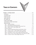
TABLE OF CONTENTS
Chapter 1: Getting Started
Introduction ............................................................................................................... 1-2
The Purpose of this Manual ...................................................................................... 1-2
Supplemental Manuals ............................................................................................. 1-2
Technical Support .................................................................................................... 1-2
Conventions Used ...................................................................................................... 1-3
Key Topics for Each Chapter..................................................................................... 1-3
Product Overview ...................................................................................................... 1-4
Quick Start Steps ....................................................................................................... 1-5
Step 1 – Unpack and Inspect .................................................................................... 1-5
Step 2 – Install Optional Hardware Accessories......................................................... 1-6
Step 3 – Become Familiar with Available Communication Ports................................ 1-7
Step 4 – Install the Programming Software and Develop a Project ........................... 1-8
Step 5 – Connect Touch Panel to Computer ............................................................ 1-9
Step 6 – Provide Power to the Touch Panel ............................................................ 1-10
Step 7 – Access the Touch Panel Setup Screens...................................................... 1-12
Step 8 – Choose Touch Panel to Device Protocol & Cables .................................... 1-13
Step 9 – Connect Touch Panel to PLC .................................................................... 1-16
Chapter 2: Specifications
Available Models........................................................................................................ 2-2
Model Specifications ................................................................................................. 2-3
Specifications common to all models ....................................................................... 2-4
6-inch Models .......................................................................................................... 2-5
8-inch and 10-inch Models ...................................................................................... 2-6
12-inch and 15-inch Models .................................................................................... 2-7
EA9-T6CL-R, EA9-T6CL (Dimensions and Ports & Memory Expansion) ................... 2-8
Table of Contents
EA9-T8CL (Dimensions and Ports & Memory Expansion) ...................................... 2-10
EA9-T10CL (Dimensions and Ports & Memory Expansion) .................................... 2-12
EA9-T12CL (Dimensions and Ports & Memory Expansion) .................................... 2-14
EA9-T15CL (Dimensions and Ports & Memory Expansion) .................................... 2-16
Mounting Clearances .............................................................................................. 2-18
EA9-T15CL Derating ............................................................................................... 2-19
Communications Ports ............................................................................................ 2-20
Handling External Memory Devices ........................................................................ 2-23
Chemical Compatibility ........................................................................................... 2-26
Chapter 3: Accessories
Accessories Overview................................................................................................. 3-2
AC/DC Power Adapter .............................................................................................. 3-3
AC/DC Power Adapter Dimensions .......................................................................... 3-5
AC/DC Power Adapter Installation ............................................................................ 3-6
Non-glare Screen Covers ........................................................................................... 3-7
Clear Screen Overlay Installation .............................................................................. 3-8
SD Card ...................................................................................................................... 3-9
USB Pen Drive ............................................................................................................ 3-9
Chapter 4: Installation and Wiring
Safety Guidelines ....................................................................................................... 4-2
Introduction ............................................................................................................... 4-3
EA9-T6CL-R and EA9-T6CL Cutout Dimensions ........................................................ 4-4
EA9-T8CL Cutout Dimensions ................................................................................... 4-5
EA9-T10CL Cutout Dimensions ................................................................................. 4-6
EA9-T12CL Cutout Dimensions ................................................................................. 4-7
EA9-T15CL Cutout Dimensions ................................................................................. 4-8
Mounting Clearances ................................................................................................ 4-9
EA9-T15CL Derating ............................................................................................... 4-10
Wiring Guidelines .................................................................................................... 4-11
ii
®
EA9-USER-M Hardware User Manual, 1st Ed. Rev B 01/15
Table of Contents
Agency Approvals................................................................................................... 4-11
Marine Use ............................................................................................................. 4-11
Providing Power to the Touch Panel ...................................................................... 4-12
DC Wiring Diagram................................................................................................ 4-12
AC Wiring Diagram ................................................................................................ 4-12
C-more LED Status Indicators ................................................................................. 4-13
Chapter 5: System Setup Screens
Introduction ............................................................................................................... 5-2
Accessing the System Setup Screens (no project loaded) ....................................... 5-3
Accessing the System Setup Screens (with project loaded) .................................... 5-4
System Setup Screens – Enable Password in Software ............................................ 5-6
System Setup Screens Flowchart ............................................................................ 5-12
Main Menu............................................................................................................... 5-13
Information Menu ................................................................................................... 5-14
Setting Menu ........................................................................................................... 5-18
Test Menu ................................................................................................................ 5-25
Memory Menu ......................................................................................................... 5-34
Chapter 6: PLC Communications
Introduction ............................................................................................................... 6-2
DirectLOGIC PLCs Password Protection.................................................................... 6-2
PLC Protocol & Cables ............................................................................................. 6-3
PLC Communication Cables & Wiring Diagrams...................................................... 6-5
AutomationDirect PLCs RS-232C Serial ..................................................................... 6-7
AutomationDirect PLCs RS-422A/RS-485A .............................................................. 6-10
DirectLOGIC Universal Isolated Network Adapter, p/n FA-ISOCON: ....................... 6-16
DirectLOGIC Universal Converter, p/n F2-UNICON: ............................................... 6-17
RS-422A/RS-485A Multi-Drop Wiring Diagram Examples ....................................... 6-18
Allen-Bradley .......................................................................................................... 6-22
GE .......................................................................................................................... 6-27
GE VersaMax Micro ................................................................................................ 6-27
Mitsubishi............................................................................................................... 6-28
EA9-USER-M Hardware User Manual, 1st Ed. Rev B 01/15
®
iii
Table of Contents
Omron ................................................................................................................... 6-30
Modicon Modbus RS-232....................................................................................... 6-31
Modicon Micro Series............................................................................................. 6-31
Modicon Modbus with RJ45 ................................................................................... 6-31
Siemens.................................................................................................................. 6-32
Chapter 7: Maintenance
Project Backup ......................................................................................................... 7-2
Check Operating Environment ................................................................................. 7-2
Check Operating Voltage ......................................................................................... 7-2
Check Status Indicators ............................................................................................ 7-2
Check Physical Conditions ........................................................................................ 7-3
Run Tests under System Setup Screens ..................................................................... 7-3
Check Memory Usage .............................................................................................. 7-4
Check/Adjust Display Brightness............................................................................... 7-4
Check Error Log ...................................................................................................... 7-4
Adjust Touch Panel................................................................................................... 7-4
Cleaning the Display Screen ..................................................................................... 7-5
Check Project Functionality ...................................................................................... 7-6
Checks from C-more Programming Software ........................................................... 7-6
Notes: ......................................................................................................................... 7-7
Chapter 8: Troubleshooting
Common Problems .................................................................................................. 8-2
Troubleshooting Flow Chart ..................................................................................... 8-3
Touch Panel does not Power up ............................................................................... 8-4
Display is Blank ........................................................................................................ 8-5
Display is Dim .......................................................................................................... 8-6
No User Program ..................................................................................................... 8-7
No Communications between Panel and PC (Personal Computer) via USB .............. 8-8
USB Driver Troubleshooting ................................................................................... 8-10
No Communications between Panel and PC (Personal Computer) via Ethernet ..... 8-12
No Communications between Panel and PLC ........................................................ 8-16
IP Address in System Setup Screens displays 0.0.0.0 .............................................. 8-19
Difficulty Connecting to the Panel over the Internet (Web server and Remote
Access features) ...................................................................................................... 8-20
iv
®
EA9-USER-M Hardware User Manual, 1st Ed. Rev B 01/15
Table of Contents
PLC Protocol Error Codes ....................................................................................... 8-21
Touch Panel Runtime Errors ................................................................................... 8-22
Panel Constantly Displays “Initializing” when Powering up .................................... 8-23
Data not Logging Problems ................................................................................... 8-23
Electrical Noise Problems ........................................................................................ 8-24
Chapter 9: Replacement Parts
Replacement Parts Overview .................................................................................... 9-2
Panel Mounting Clip Replacements – EA9-BRK ........................................................ 9-3
Logo Label Replacement Insert - EA9-LBL ................................................................ 9-4
3-wire Communications Terminal Block – EA9-3TB.................................................. 9-4
DC Panel Power Connector Replacement – EA-DC-CON ......................................... 9-5
AC Power Adapter Connector Replacement– EA-AC-CON....................................... 9-6
Panel Gasket Replacements – EA9-xx-GSK ............................................................... 9-7
Gasket Replacement Installation Instructions: ......................................................... 9-7
Appendix A: Panel and PLC Error Code Tables
Introduction ............................................................................................................... A-2
C-more Touch Panel Error Code Table ..................................................................... A-3
DirectLOGIC – Panel Error Code PLC-499 Explanation ............................................ A-5
DirectLOGIC K-Sequence Protocol – PLC Error Code Table ..................................... A-5
DirectLOGIC DirectNET Protocol – PLC Error Codes ................................................ A-5
Modbus Protocols Error Code P499 Explanation ..................................................... A-6
AutomationDirect CLICK .......................................................................................... A-6
AutomationDirect DirectLOGIC - Modbus (Koyo) ..................................................... A-6
Modicon Modbus RTU ............................................................................................. A-6
Entivity Modbus RTU ................................................................................................ A-6
DirectLOGIC ECOM Protocol – PLC Error Codes ...................................................... A-6
Productivity3000 Error Code P499 ............................................................................ A-7
Allen-Bradley – Panel Error Code PLC-499 Explanation ........................................... A-8
Allen-Bradley DF1 & DH485 Protocols – PLC Error Code Tables ............................. A-9
EA9-USER-M Hardware User Manual, 1st Ed. Rev B 01/15
®
v
Table of Contents
Allen-Bradley EtherNet/IP Protocol –
Panel Error Code PLC-496, 497 and 498 Explanation ............................................ A-11
Allen-Bradley – EtherNet/IP Protocol – PLC Error Code Tables ControlLogix,
CompactLogix, & FlexLogix..................................................................................... A-12
Allen-Bradley – EtherNet/IP Protocol – PLC Error Code Tables ............................. A-16
Generic EtherNet IP Protocol – PLC Error Codes ................................................... A-21
GE 90-30 – Panel Error Code PLC-499 Explanation ................................................ A-22
GE 90-30 SNPX Protocol – PLC Error Code Tables ................................................. A-23
Mitsubishi FX Protocol – PLC Error Codes .............................................................. A-32
Omron – Panel Error Code PLC-499 Explanation ................................................... A-32
Omron Host Link Protocol – PLC Error Code Table ............................................... A-33
Omron FINS Protocol – PLC Error Code Table ....................................................... A-34
Omron – Panel Error Code P495 Explanation ........................................................ A-37
Omron CS/CJ FINS Ethernet Protocol – PLC Error Code Table.............................. A-38
Siemens – Panel Error Code P499 Explanation....................................................... A-39
Siemens PPI Protocol – PLC Error Code Table........................................................ A-40
Siemens ISO over TCP Protocol – PLC Error Code Table ....................................... A-41
Appendix B: Touch Panel Runtime Errrors
Introduction .B-2
Runtime Errors ........................................................................................................... B-3
Log File Naming ....................................................................................................... B-4
vi
®
EA9-USER-M Hardware User Manual, 1st Ed. Rev B 01/15