1
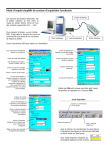
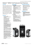
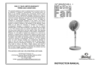
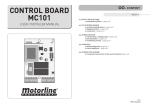
ACCESSORIES
CHAPTER
3
In This Chapter...
Accessories Overview................................................................................................. 3-2
AC/DC Power Adapter .............................................................................................. 3-3
AC/DC Power Adapter Dimensions .......................................................................... 3-5
AC/DC Power Adapter Installation ............................................................................ 3-6
D-SUB 15-pin to Terminal Block Adapters ................................................................ 3-7
Non-glare Screen Covers ........................................................................................... 3-8
Clear Screen Overlay Installation .............................................................................. 3-9
SD Card .................................................................................................................... 3-10
USB FLASH Drive ..................................................................................................... 3-10
Chapter 3 - Accessories
Accessories Overview
1
2
3
4
5
6
7
8
9
10
11
12
13
14
A
B
C
D
EA-AC
AC / DC Power Adapter
EA-x-COV2
Screen Protector
EA-COMCON-3A
DSUB Port Adapter
EA-SD-CARD
SD Card
C-more Touch Panel
Part Number
EA-AC
EA-6-COV2
EA-8-COV2
EA-10-COV2
EA-12-COV2
EA-15-COV2
EA-SD-CARD
USB-FLASH
EA-COMCON-3
or
EA-COMCON-3A
3-2
USB-FLASH
USB Pen Drive
Description
AC/DC Adapter for C-more EA7 and EA9 series touch panels; powered from a 100-240 VAC, 50/60 Hertz
power source. Provides 24VDC at 1.5A. Power Fault features help protect data being logged to Compact
Flash or SD card during power failures. C-more EA7 series panels must have firmware version 1.21 Build
6.18E or higher for proper operation.
Non-glare protective overlay, 6-inch, protects C-more touch screen and helps reduce glare from external
light sources. Compatible with C-more EA7 and EA9 series and C-more Micro-Graphic 6-inch panels.
Package of 3.
Non-glare protective overlay, 8-inch, protects C-more touch screen and helps reduce glare from external
light sources. Compatible with C-more EA7 and EA9 series 8-inch panels. Package of 3.
Non-glare protective overlay, 10-inch, protects C-more touch screen and helps reduce glare from external
light sources. Compatible with C-more EA7 and EA9 series 10-inch panels. Package of 3.
Non-glare protective overlay, 12-inch, protects C-more touch screen and helps reduce glare from external
light sources. Compatible with C-more EA7 and EA9 series 12-inch panels. Package of 3.
Non-glare protective overlay, 15-inch, protects C-more touch screen and helps reduce glare from external
light sources. Compatible with C-more EA7 and EA9 series 15-inch panels. Package of 3.
SD memory card for non-volatile storage, 2GB industrial grade. 85 degrees C maximum operating
temperature makes it suitable for data logging in industrial applications. Recommended for the C-more
EA9 series touch panels.
USB Flash drive, SanDisk, 4GB (SanDisk P/N SDCZ50-004G-A46). Recommended for use with the
C-more touch panels and Productivity3000 controllers.
D-SUB 15-pin to 6-terminal PLC serial communication port adapter to allow wire terminal connections for
RS-422/485 PLC communication cable.
EA-COMCON-3 is low profile and will only fit on EA9-T6CL(-R)
EA-COMCON-3A is straight and fits EA-T8CL, EA9-T10CL, EA9-T12CL and EA9-T15CL
®
EA9-USER-M Hardware User Manual, 1st Ed. Rev B 01/15
Chapter 3 - Accessories
AC/DC Power Adapter
The optional C-more AC/DC Power Adapter can be used to power the C-more touch panels
from a 100-240 VAC, 50/60 Hertz, voltage source. The adapter provides 24 VDC @ 1.5 A
to the touch panel’s DC power connector and can be conveniently secured to the touch panel
with two captive screws. The adapter provides a power loss signal to the touch panel that
causes the touch panel to stop writing data to SD memory devices providing a controlled
shutdown for increased data logging reliability.
Part No. EA-AC
AC/DC Adapter Wiring
AC Power Adapter
Not recommended for use with the EA7-T15C
when operating temperatures are expected
to be above 40 deg C.
Recommended AC Supply Fuse
3.0 A time delay, ADC p/n MDL3
100 - 240 VAC
50/60 Hz
Tightening Torque
Power supply cable torque
Power connector mounting torque
Mounting flange screw torque
71 - 85 oz-in (0.5 - 0.6 Nm)
71 - 85 oz-in (0.5 - 0.6 Nm)
57 - 71 oz-in (0.4 - 0.5 Nm)
NOTE: Use 60 / 75 °C copper conductors only
EA9-USER-M Hardware User Manual, 1st Ed. Rev B 01/15
®
1
2
3
4
5
6
7
8
9
10
11
12
13
14
A
B
C
D
3-3
Chapter 3 - Accessories
AC/DC Power Adapter Specifications
1
2
3
4
5
6
7
8
9
10
11
12
13
14
A
B
C
D
3-4
Part Number
Input Voltage & frequency
Operating Temperature Range
Storage Temperature Range
Operating & Storage Humidity
Noise Immunity
EA-AC
100-240 VAC; 50/60 Hertz
0 °C to 50 °C [32 to 122 °F] Maximum surrounding temperature rating, 50 °C
-20 to 60 °C [-4 to 140 °F]
10-85% RH (non-condensing)
1000 VAC p-p (Pulse width 1 µs, rise time: 1 ns)
With proper ground connection on AC terminal block.
Hi-pot
1000 VAC, 1 minute
With proper ground connection on AC terminal block.
Insulation Resistance
500 VDC, 10 M ohm or above
With proper ground connection on AC terminal block.
Compliant with IEC61131-2
Pulse shape: Sine half wave, Peak acceleration: 147 m/s2 (15 G),
X, Y, Z: 3 directions, 2 times each
140 °C [284 °F], with autorecovery
85 VAC: 2.6 A, 100 VAC: 2.8 A, 264 VAC: 3.9 A
Vibration
Shock
Thermal Protection
Short Circuit Protection
Static Electricity Discharge
Resistance
Agency Approvals
Environment
Grounding
Weight
Removable AC Power Connector
Output Current
Inrush Current
Recommended AC Supply Fuse
Power Supply Cable Torque
Mounting to Touch Panel
Compliant with IEC61000-4-2, Contact: 4 kV, Air: 8 kV
UL508, UL Recognized, cUL, CE, EMC EN61132-2
For use in pollution degree 2 environment
Ground resistance: less than 100 ohm
6.13 oz. [175 g]
EA-AC-CON or DECA Switchlab MC101-508-03G
Secure with (2) captive M2.5 screws, torque to 70 oz-in [0.5 Nm]
Maximum 1.5 A
For 100 VAC: 15 A, 3 ms or less
For 240 VAC: 20 A, 3 ms or less
3.0 A time delay, ADC p/n MDL3
71 - 85 oz-in (0.5 - 0.6 Nm)
Secure with (2) spring loaded captive M3-20 screws, torque to 50 oz-in [0.35 Nm]
NOTE: Logic within the EA-AC will turn off the backlight instantly when a power failure is detected to allow the CPU
to run longer. The backlight turns on automatically when the power returns to the C-more operating voltage.
®
EA9-USER-M Hardware User Manual, 1st Ed. Rev B 01/15
Chapter 3 - Accessories
AC/DC Power Adapter Dimensions
Dimensions
AC Power Label
Screw
3.661
[93.0]
3.001
[76.2]
FRONT VIEW
Screw
SIDE VIEW
DC Power
Connector
REAR VIEW
AC Power
Connector
Units: inches [mm]
1.421 ±0.02
[36.1 ± 0.5]
0.579
[14.7]
BOTTOM VIEW
Panel Depth with AC/DC Power Adapter Installed
A
Units: inches[mm]
Part Number
EA9-T6CL-R
EA9-T6CL
EA9-T8CL
EA9-T10CL
EA9-T12CL
EA9-T15CL
A
2.991 [76.0]
2.991 [76.0]
3.511 [89.2]
3.511 [89.2]
3.351 [85.8]
3.351 [85.1]
EA9-USER-M Hardware User Manual, 1st Ed. Rev B 01/15
®
1
2
3
4
5
6
7
8
9
10
11
12
13
14
A
B
C
D
3-5
Chapter 3 - Accessories
AC/DC Power Adapter Installation
WARNING: This procedure should only be performed by qualified personnel who are experienced in
1
working with electronic equipment. Take the necessary steps to prevent damage that may be caused by
static electricity discharge. Disconnect input power to the touch panel before proceeding.
2
2
3 1
4
5
6
7 Preparation: Place the touch panel face down on a lint-free soft
Insert the AC/DC power adapter into the touch panel’s 5-position DC
surface to prevent scratching the display screen if not already installed
power connector.
in a control cabinet. Remove the DC power connector if it is installed.
8
4
9 3
10
11
12
13 Secure the AC/DC Power Adapter to the touch panel by tightening the
Plug the wired 3-pin AC Power Connector into its mating connector
on the adapter and secure in place by tightening the two (2) captive
two (2) spring loaded captive M3-20 screws to a torque of 50 oz-in
M2.5 screws to a torque of 70 oz-in [0.5 Nm].
[0.35 Nm].
14
A
B
C
D
3-6
®
EA9-USER-M Hardware User Manual, 1st Ed. Rev B 01/15
Chapter 3 - Accessories
D-SUB 15-pin to Terminal Block Adapters
These adapters are plugged into the 15-pin serial port on the rear of the panels to allow
wire terminal connections for RS-422/485 PLC communication cable. The wiring of both
adapters is the same.
EA-COMCON-3 is used with EA9-T6CL(-R). EA-COMCON-3 is UL Recognized.
EA-COMCON-3A is NOT UL Recognized or Listed. It is used with EA9-T8CL,
EA9-T10CL, EA9-T12CL and EA9-T15CL
EA-COMCON-3
EA-COMCON-3A
Dimensions
Dimensions
0.60
[15.3]
Units: inches [mm]
Units: inches [mm]
1.756
[44.6]
Date code
Country of Origin
2.07
[52.6]
1.873
[47.6]
1.126
[28.6]
TERM
RD+
RD–
SD+
EA-COMCON-3
SD–
GND
KOYO ELECTRONICS INDUSTRIES CO., LTD.
0.68
[17.4]
Wiring Diagram
1.70
[43.2]
D-SUB 15-pin to Terminal Block Adapters
(P/Ns EA-COMCON-3 & EA-COMCON-3A)
Wiring Diagram
GND
SD–
12
TXD–
TERM
RD+
RD–
SD+
SD–
Terminals
GND
5
GND
SD+
11
TXD+
RD–
10
RXD–
15-pin
D-sub
(male)
15
9
RD+
RXD+
TERM
13
TERM
1
EA9-USER-M Hardware User Manual, 1st Ed. Rev B 01/15
®
1
2
3
4
5
6
7
8
9
10
11
12
13
14
A
B
C
D
3-7
Chapter 3 - Accessories
Non-glare Screen Covers
1
2
3
4
5
6
7
8
9
10
11
12
13
14
A
B
C
D
3-8
Non Glare 6 Inch Screen Cover, protective overlay used to protect the touch screen while
helping to reduce the glare from external light sources. (pk of 3)
Part No. EA-6-COV2, EA-8-COV2, EA-10-COV2, EA-12-COV2 & EA-15-COV2
Units: inches [mm]
0.197
[5.0]
12.563
[319.1]
Adhesive
0.157
[4.0]
EA-15-COV2
10.260
[260.6]
0.197
[5.0]
0.157
[4.0]
EA-12-COV2
0.197
[5.0]
8.906
[226.2]
0.157
[4.0]
9.374
[238.1]
EA-10-COV2
0.197
[5.0]
7.315
[185.8]
7.642
[194.1]
0.157
[4.0]
EA-8-COV2
6.614
[168.0]
4.913
[124.8]
0.197
[5.0]
5.441
[138.2]
EA-6-COV2
0.157
[4.0]
15”
12”
3.795
[96.4]
10”
8”
6”
®
EA9-USER-M Hardware User Manual, 1st Ed. Rev B 01/15
Chapter 3 - Accessories
Non-glare Screen Covers (cont’d)
Clear Screen Overlay Installation
Step 1
Step 2
Check to be sure that the proper size non-glare screen cover is being
used on the subject touch panel. Notice that the outer perimeter of the
screen cover has an adhesive band. The adhesive band will be located
on the outside edge of the touch panel’s white frame bordering the
touch area when installed.
Step 3
Start in one corner and peel the screen cover from the backing.
Step 4
Align the screen cover over the touch panel’s white frame, then start
on one side and gently lay the cover over the entire touch area.
Smooth out the screen cover and press all around the outside
perimeter to secure the cover in place. The screen cover can be
removed by lifting up on the small tab and gently pulling the cover
away form the touch panel’s surface.
Step 5
Remove the protective sheet.
NOTE: The protective cover ships with a thin protective sheet on the face of the cover that needs to be carefully
removed. If your panel is not clear, the protective sheet may not have been removed.
EA9-USER-M Hardware User Manual, 1st Ed. Rev B 01/15
®
1
2
3
4
5
6
7
8
9
10
11
12
13
14
A
B
C
D
3-9
Chapter 3 - Accessories
SD Card
SD memory card for non-volatile storage, 2GB industrial grade. 85° C maximum operating
1
temperature makes it suitable for data logging in industrial applications. Recommended for
the C-more EA9 series touch panels. The SD card is the fastest option for writing data. If
2
logged data is saved to external memory, AutomationDirect recommends using an
EA-SD-CARD.
3
4
5
6
7
8 USB FLASH Drive
USB-FLASH sold by AutomationDirect has been tested with C-more panels and is Hi-Speed
USB 2.0 certified.
9
Part No. USB-FLASH
10
11
12
13
14
A
B
C
D
3-10
®
EA9-USER-M Hardware User Manual, 1st Ed. Rev B 01/15