1
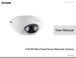
E-Series Optical Splice Patch Storage
Tray-Based System
User Manual
E-Series Optical Splice Patch Storage
Tray-Based System
User Manual, Part Number 136328-2
Copyright 2011, Telect, Inc., All Rights Reserved
Telect and Connecting the Future are registered trademarks of Telect, Inc.
Telect assumes no liability from the application or use of these products. Neither does Telect convey any
license under its patent rights nor the patent rights of others. This document and the products described
herein are subject to change without notice.
About Telect
Telect offers complete solutions for physical layer connectivity, power, equipment housing and other
network infrastructure equipment. From outside plant and central office to inside the home, Telect draws
on more than 25 years of experience to deliver leading edge product and service solutions. Telect is
committed to providing superior customer service and is capable of meeting the dynamic demands of
customer and industry requirements. This commitment to customer and industry excellence has positioned
Telect as a leading connectivity and power solution provider for the global communications industry.
Technical Support
E-mail: [email protected]
Phone: 888.821.4856 or 509.921.6161
Telect, Inc. • USA +1.509.926.6000 • Mexico +52.33.3836.37.52
www.telect.com • © 2011 Telect, Inc., All Rights Reserved, 136328-2 A0
Page ii
E-Series Optical Splice Patch Storage
User Manual
Table of Contents
Chapter 1: Description .............................................................................................................. 1
1.1 Overview .......................................................................................................................... 1
1.2 Main Assemblies .............................................................................................................. 1
1.3 Chassis Assemblies ......................................................................................................... 2
1.4 Trays ................................................................................................................................. 2
1.4.1 Patch Trays ............................................................................................................. 4
1.4.2 Splice Trays ............................................................................................................. 7
1.4.3 Combination Splice and Patch Trays ..................................................................... 10
1.4.4 Storage Tray .......................................................................................................... 14
1.5 Specifications ................................................................................................................. 16
1.5.1 Physical ................................................................................................................. 16
1.5.2 Environment .......................................................................................................... 16
1.5.3 Mounting ............................................................................................................... 16
1.5.4 Cable Compatibility ............................................................................................... 17
1.5.5 Adapter Choices .................................................................................................... 17
1.5.6 Optical Protections ................................................................................................ 17
1.5.7 Optical Performance ............................................................................................. 17
1.5.8 Compliance ........................................................................................................... 17
Chapter 2: Chassis Installation .............................................................................................. 19
Chapter 3: Tray Installation ..................................................................................................... 21
Chapter 4: Splice Tray Cabling............................................................................................... 23
Chapter 5: Patch Tray Cabling ................................................................................................ 29
Chapter 6: Splice-Patch Tray Cabling..................................................................................... 33
Chapter 7: Service ................................................................................................................... 41
7.1 In-Warranty Service ....................................................................................................... 41
7.2 Repacking for Shipment ................................................................................................. 41
7.3 Maintenance .................................................................................................................. 41
7.3.1 Cleaning Connectors & Adapters .......................................................................... 41
7.3.2 Adapter Replacement ........................................................................................... 42
Chapter 8: Accessories ........................................................................................................... 43
Appendix A: Fiber Color Code................................................................................................. 47
Telect, Inc. • USA +1.509.926.6000 • Mexico +52.33.3836.37.52
www.telect.com • © 2011 Telect, Inc., All Rights Reserved, 136328-2 A0
Page iii
List of Figures
Figure 1 - ESTF-06TR-4RU ......................................................................................................... 1
Figure 2 - E-Series 1RU Chassis (ESTF-01TR-1RU) With a Splice/Patch Tray ......................... 1
Figure 3 - Model ESTF-06TR-4RU Chassis ................................................................................ 2
Figure 4 - Tray Components ........................................................................................................ 3
Figure 5 - Model ESTF-P024-USC-000 Patch Tray ..................................................................... 3
Figure 6 - Model ESTF-P012-UFC-000 Patch Tray ..................................................................... 4
Figure 7 - Model ESTF-P012-ULC-000 Patch Tray ..................................................................... 4
Figure 8 - ESTF-P024-USC-000 With IFC Multi-Fiber on the Left & Jumpers
(or Patch Cords) on the Right ...................................................................................... 6
Figure 9 - ESTF-P012-USC-000 With Same-Side Entry of Jumpers and OSP Fiber
(in Protective Tubing) on the Right .............................................................................. 7
Figure 10 - Model ESTR-S024-000-000 Splice Tray ................................................................... 8
Figure 11 - Model ESTR-S012-000-000 Splice Tray ................................................................... 8
Figure 12 - ESTF-S024-000-000 With IFC Multi-Fiber Subunits on the Left & OSP
Multi-Fiber in Protective Tubing on the Right ............................................................. 9
Figure 13 - ESTF-S012-000-000 With Same-Side Fiber Entry on the Right ............................. 10
Figure 14 - Model ESTF-C012-USC-000 Splice/Patch Tray....................................................... 10
Figure 15 - Model ESTF-C024-UFC-000 Splice/Patch Tray ...................................................... 11
Figure 16 - Model ESTF-C024-ULC-000 Splice/Patch Tray ...................................................... 11
Figure 17 - ESTF-C024-USC-000 With IFC Multi-Fiber Subunits on the Left & Jumpers
(or Patch Cords) on the Right .................................................................................. 13
Figure 18 - Model ESTR Storage Tray ...................................................................................... 14
Figure 19 - ESTR Storage Tray Routing Schemes (Opposite Side Entries/Exits) ..................... 15
Figure 20 - ESTR Storage Tray Routing Schemes (Same-Side Entries/Exits) .......................... 16
Figure 21 - Installing Brackets ................................................................................................... 19
Figure 22 - Disconnecting Linkage Using a Pen Point ............................................................... 19
Figure 23 - Disconnecting Linkage Using Tray Removal Tool.................................................... 20
Figure 24 - Mounting Chassis to Rack ....................................................................................... 20
Figure 25 - Installing Trays ........................................................................................................ 21
Figure 26 - Using the Tray Removal Tool .................................................................................. 22
Figure 27 - E-Series 24-Position Splice Tray (Model ESTF-S024-000-000) ............................. 23
Figure 28 - IFC Breakout Specifications .................................................................................... 24
Figure 29 - I/O Cable Breakout Specifications ........................................................................... 25
Figure 30 - Cassette Assembly (Exploded) ............................................................................... 26
Figure 31 - Clockwise Vs Counter-Clockwise Routing in a Cassette ......................................... 27
Figure 32 - Example of a 24-Circuit Interconnect Between OSP Fiber Entering
on the Right and IFC Fiber Entering on the Left ...................................................... 28
Telect, Inc. • USA +1.509.926.6000 • Mexico +52.33.3836.37.52
www.telect.com • © 2011 Telect, Inc., All Rights Reserved, 136328-2 A0
Page iv
Figure 33 - E-Series 24-Position Patch Tray (Model ESTF-P024-000) ..................................... 29
Figure 34 - IFC Multi-fiber Breakout Specifications ................................................................... 30
Figure 35 - ESTF-P024-USC-000 with IFC Multi-fiber on the Left & Jumpers on the Right ...... 31
Figure 36 - ESTF-P012-USC-000 With Same-Side Entry on the Right ..................................... 32
Figure 37 - E-Series 24-Position Patch \ Splice Tray (Model ESTF-C024-USC-000) ............... 33
Figure 38 - IFC Breakout Specifications .................................................................................... 34
Figure 39 - I/O Cable Breakout Specifications ........................................................................... 35
Figure 40 - Cassette Assembly (Exploded) ............................................................................... 36
Figure 41 - First Feeder .............................................................................................................. 37
Figure 42 - First Pigtail ............................................................................................................... 38
Figure 43 - Routing the Fiber ..................................................................................................... 39
Figure 44 - Replacing SC Adapters ........................................................................................... 42
Telect, Inc. • USA +1.509.926.6000 • Mexico +52.33.3836.37.52
www.telect.com • © 2011 Telect, Inc., All Rights Reserved, 136328-2 A0
Page v
Chapter 1: Description
1.1 Overview
E-Series is an advanced, fiberoptic cable management
system. The E-Series provides a
central location for fiber
patching, splicing, and storage.
Telect engineered the E-Series
for central office (CO), customer
premises, or for any ETSI
application where rear access to
equipment is limited or
Figure 1 - ESTF-06TR-4RU
impractical. Cable management
includes articulated links that allow slide-out access to patch adapters mounted on pull-up
carriers in addition to slide-out access to splice cassettes. You can order trays with pull-up
adapters to accommodate 12 or 24 sets of FC, ST, SC, LC, or E2000 fiber connectors.Trays are
available with or without preterminated feeder or connectorized pigtails.
1.2 Main Assemblies
•
A chassis (rack shelf) assembly
•
Any assortment of patch, splice,
combination splice/patch, and
storage trays that slide into the
chassis assemblies
•
Routing and protection hardware for
incoming and outgoing fiber cable
•
Industry-standard, multi-fiber cable
assemblies and pigtail bundles
Figure 2 - E-Series 1RU Chassis (ESTF-01TR1RU) With a Splice/Patch Tray
Telect, Inc. • USA +1.509.926.6000 • Mexico +52.33.3836.37.52
www.telect.com • © 2011 Telect, Inc., All Rights Reserved, 136328-2 A0
Page 1
1.3 Chassis Assemblies
E-Series chassis fit standard 485mm (19-in.) ETSI racks. Each
chassis holds up to six trays:
•
1 RU, 1-Tray Chassis (Model
ESTF-01TR-1RU)
•
2 RU, 3-Tray Chassis (Model
ESTF-03TR-2RU)
•
3 RU, 4-Tray Chassis (Model
ESTF-04TR-3RU)
•
Figure 3 - Model ESTF-06TR-4RU Chassis
4 RU, 6-Tray Chassis (Model ESTF-06TR-4RU)
Each chassis is black with built-in front entry/exit arcs and tray slide receivers. M6 rack mounting
screws are included. Standard chassis are available in black.
1.4 Trays
Telect offers an assortment of trays for patching, splicing, and storage. All tray are black steel
with black cable routing arcs and guides. All trays are front corner cable entry and exit through
Telect’s patented, articulated link system along right and left sides of the trays, forming channels
that maintain critical bend-radius control when trays are extended and retracted.
From the factory, each tray is configured for either 12 or 24 circuits. The following table outlines
the number of possible terminations for each of the four chassis assemblies. Mixing 12 and 24
circuit trays in a single chassis accounts for any standard IFC and OSP cable capacity. Telect
also offers adapter and splice cassette kits to boost the capacity of 12-circuit patch and splice
trays up to 24 circuits.
Chassis Assemblies
12 Terminations per tray, up to
24 Terminations per tray, up to
ESTF-01TR-1RU
12 Circuits Per Chassis
24 Circuits Per Chassis
ESTF-03TR-2RU
36 Circuits Per Chassis
72 Circuits Per Chassis
ESTF-04TR-3RU
48 Circuits Per Chassis
96 Circuits Per Chassis
ESTF-06TR-4RU
72 Circuits Per Chassis
144 Circuits Per Chassis
In a loaded rack or optical distribution cabinet, such as shown on the cover, a single bay or
cabinet can hold as many as 1440 terminations (10 chassis x 6 trays per chassis x 24
terminations per tray).
The following paragraphs detail some of the forms and features of each Telect E-Series Tray:
•
“1.4.1 Patch Trays” on page 3
•
“1.4.2 Splice Trays” on page 7
Telect, Inc. • USA +1.509.926.6000 • Mexico +52.33.3836.37.52
www.telect.com • © 2011 Telect, Inc., All Rights Reserved, 136328-2 A0
Page 2
•
“1.4.3 Combination Splice and Patch Trays” on page 10
•
“1.4.4 Storage Tray” on page 14
A rticulated Linkage
E ntry for S ubunit or P rotective Loose
T ubing at O ne F ront C orner and
P atch C ords at the O ther
C ircuit 23 on T op
C ircuit 24 on B ottom
T w o 12-P osition S plice C assettes
C ircuit 1 on T op
C ircuit 2 on B ottom
R outing G uides and A rcs
B ay/P anel/T ray ID
P ull-U p A dapter C arriers
D esignation Label
Figure 4 - Tray Components
1.4.1 Patch Trays
From the factory, E-Series Patch Trays have either 12 or 24 adapters. Trays are available with all
of the standard choices of adapters and polishes.
Use E-Series Patch Trays for cross-connect patching, interconnections between IFC and
network element, and interconnections between network elements.
Figure 5 - Model ESTF-P024-USC-000 Patch Tray
Telect, Inc. • USA +1.509.926.6000 • Mexico +52.33.3836.37.52
www.telect.com • © 2011 Telect, Inc., All Rights Reserved, 136328-2 A0
Page 3
Figure 6 - Model ESTF-P012-UFC-000 Patch Tray
Figure 7 - Model ESTF-P012-ULC-000 Patch Tray
The 6 or 12 pull-up carriers per tray support 2 over-and-under adapters each. Patch trays include
on-board retermination storage (about .5 m) for each subunit or loose tube. Also, patch trays
come with cable and connector management hardware, tray slides, and a designation strip.
Telect, Inc. • USA +1.509.926.6000 • Mexico +52.33.3836.37.52
www.telect.com • © 2011 Telect, Inc., All Rights Reserved, 136328-2 A0
Page 4
The following table lists standard Telect E-Series Patch Trays. The “000” at the end of a model
number designates that a particular tray does not includes factory-installed cable. But factoryinstalled, connectorized IFC is available up to “999” meters, for example, ESTF-P012-USC-500.
Table 1 - Standard Telect E-Series Patch Trays
Patch Tray
Ports
(Terminations)
Adapters & Polishs
ESTF-P012-USC-000
12
SC/UPC
ESTF-P012-ASC-000
12
SC/APC
ESTF-P012-ULC-000
6
LC/UPC
ESTF-P012-ALC-000
6
LC/APC
ESTF-P012-UE2-000
12
E2000/UPC
ESTF-P012-AE2-000
12
E2000/APC
ESTF-P012-UFC-000
12
FC/UPC
ESTF-P024-USC-000
24
SC/UPC
ESTF-P024-ASC-000
24
SC/APC
ESTF-P024-ULC-000
12
LC/UPC
ESTF-P024-ALC-000
12
LC/APC
ESTF-P024-UE2-000
24
E2000/UPC
ESTF-P024-AE2-000
24
E2000/APC
ESTF-P024-UFC-000
24
FC/UPC
Telect, Inc. • USA +1.509.926.6000 • Mexico +52.33.3836.37.52
www.telect.com • © 2011 Telect, Inc., All Rights Reserved, 136328-2 A0
Page 5
The following illustrations show typical routing schemes.
~ 11 00 m m
12
24
11
23
10
22
9
21
8
20
7
19
6
18
5
17
4
16
3
15
2
14
1
13
~ 11 50 m m
~ 12 00 m m
Figure 8 - ESTF-P024-USC-000 With IFC Multi-Fiber on the Left & Jumpers (or Patch
Cords) on the Right
Telect, Inc. • USA +1.509.926.6000 • Mexico +52.33.3836.37.52
www.telect.com • © 2011 Telect, Inc., All Rights Reserved, 136328-2 A0
Page 6
12
24
11
23
10
22
9
21
8
20
7
19
6
18
5
17
4
16
3
15
2
14
1
13
Figure 9 - ESTF-P012-USC-000 With Same-Side Entry of Jumpers and OSP Fiber
(in Protective Tubing) on the Right
1.4.2 Splice Trays
E-Series Splice Trays have either one or two, 12-place splice cassettes. ESTR-S012-000-000
(one cassette) accommodates 12, and ESTR-S024-000-000 (two cassettes) accommodates 24
heat-shrink fusion splices. Trays provide on-board retermination storage (about .5 m) for each
subunit or loose tube, and cassettes provide about 1 m of retermination storage for each
fiber strand.
Splice trays include storage arcs, cable and connector management hardware, tray slides, and a
designation strip.
Telect, Inc. • USA +1.509.926.6000 • Mexico +52.33.3836.37.52
www.telect.com • © 2011 Telect, Inc., All Rights Reserved, 136328-2 A0
Page 7
The “000-000” at the end of splice model numbers designates that the splice trays include neither
adapters nor factory-installed fiber.
Figure 10 - Model ESTR-S024-000-000 Splice Tray
Figure 11 - Model ESTR-S012-000-000 Splice Tray
Telect, Inc. • USA +1.509.926.6000 • Mexico +52.33.3836.37.52
www.telect.com • © 2011 Telect, Inc., All Rights Reserved, 136328-2 A0
Page 8
The following illustrations show typical routing schemes.
02–ORANGE
01–BLUE
12
24
11
23
10
22
9
21
8
20
7
19
6
18
5
17
4
16
3
15
2
14
1
13
Figure 12 - ESTF-S024-000-000 With IFC Multi-Fiber Subunits on the Left & OSP
Multi-Fiber in Protective Tubing on the Right
Telect, Inc. • USA +1.509.926.6000 • Mexico +52.33.3836.37.52
www.telect.com • © 2011 Telect, Inc., All Rights Reserved, 136328-2 A0
Page 9
12
24
11
23
10
22
9
21
8
20
7
19
6
18
5
17
4
16
3
15
2
14
1
13
Figure 13 - ESTF-S012-000-000 With Same-Side Fiber Entry on the Right
1.4.3 Combination Splice and Patch Trays
From the factory, E-Series Combination Splice/Patch Trays have either 12 or 24 adapters with
one or two 12-place splice cassettes to match. Trays are available with all of the standard
choices of adapters and polishes — same as the patch trays.
Figure 14 - Model ESTF-C012-USC-000 Splice/Patch Tray
Telect, Inc. • USA +1.509.926.6000 • Mexico +52.33.3836.37.52
www.telect.com • © 2011 Telect, Inc., All Rights Reserved, 136328-2 A0
Page 10
Figure 15 - Model ESTF-C024-UFC-000 Splice/Patch Tray
Figure 16 - Model ESTF-C024-ULC-000 Splice/Patch Tray
Like the patch trays, each pull-up carrier supports two over-and-under adapters. Splice/patch
trays include cable and connector management hardware, tray slides, and a designation strip.
The trays can be ordered with or without connectorized pigtails.
The following table lists all standard Telect E-Series Splice/Patch Trays. In the table, a blank or
“0 0 0” at the end of a model numbers designates that a particular splice/patch tray does not
include factory-installed connectorized pigtails. “L D D” at the end signifies factory-installed,
connectorized 2-m pigtails routed from the cassette’s splice holders to the adapters.
The illustration that follows shows the typical routing scheme.
Telect, Inc. • USA +1.509.926.6000 • Mexico +52.33.3836.37.52
www.telect.com • © 2011 Telect, Inc., All Rights Reserved, 136328-2 A0
Page 11
Splice/Patch Traya
Terminations
Adapters & Polish
ESTF-C012-USC-_ _ _
12
SC/UPC
ESTF-C012-ASC-_ _ _
12
SC/APC
ESTF-C012-ULC-_ _ _
6
LC/UPC
ESTF-C012-ALC-_ _ _
6
LC/APC
ESTF-C012-UE2-_ _ _
12
E2000/UPC
ESTF-C012-AE2-_ _ _
12
E2000/APC
ESTF-C012-UFC-_ _ _
12
FC/UPC
ESTF-C012-UST-_ _ _
12
ST/UPC
ESTF-C024-USC-_ _ _
24
SC/UPC
ESTF-C024-ASC-_ _ _
24
SC/APC
ESTF-C024-ULC-_ _ _
12
LC/UPC
ESTF-C024-ALC-_ _ _
12
LC/APC
ESTF-C024-UE2-_ _ _
24
E2000/UPC
ESTF-C024-AE2-_ _ _
24
E2000/APC
ESTF-C024-UFC-_ _ _
24
FC/UPC
ESTF-C024-UST-_ _ _
24
ST/UPC
a. Blank or 0 0 0 for ordering trays without factory-installed pigtails or
0 0 2 for factory-installed, connectorized pigtails
Telect, Inc. • USA +1.509.926.6000 • Mexico +52.33.3836.37.52
www.telect.com • © 2011 Telect, Inc., All Rights Reserved, 136328-2 A0
Page 12
Figure 17 - ESTF-C024-USC-000 With IFC Multi-Fiber Subunits on the Left & Jumpers
(or Patch Cords) on the Right
Telect, Inc. • USA +1.509.926.6000 • Mexico +52.33.3836.37.52
www.telect.com • © 2011 Telect, Inc., All Rights Reserved, 136328-2 A0
Page 13
1.4.4 Storage Tray
The E-Series Storage Tray (Model ESTR) stores jumper or patch cord slack. Single pass-through
storage can vary in lengths from less than 1 m up to nearly 3 m. Maximum number of jumpers or
patch cords depends on their diameter versus the capacity of the articulated linkage.
Figure 18 - Model ESTR Storage Tray
The following cabling capacities assume very dense packing. Use this list for comparison
purposes only; avoid over-packing.
•
~90 cables (1.75 mm dia.)
•
~64 cables (2 mm dia.)
•
~32 cables (3 mm dia.)
Telect, Inc. • USA +1.509.926.6000 • Mexico +52.33.3836.37.52
www.telect.com • © 2011 Telect, Inc., All Rights Reserved, 136328-2 A0
Page 14
The following illustrations show typical routing schemes. Other schemes are possible. Trays can
accommodate combinations of routing schemes. Jumpers and patch cords can enter/exit at
opposite corners or at the same-side corner.
<1 m
~ 1 .5 m
>1 m
2m
Figure 19 - ESTR Storage Tray Routing Schemes (Opposite Side Entries/Exits)
Telect, Inc. • USA +1.509.926.6000 • Mexico +52.33.3836.37.52
www.telect.com • © 2011 Telect, Inc., All Rights Reserved, 136328-2 A0
Page 15
~ 2 .5 m
Figure 20 - ESTR Storage Tray Routing Schemes (Same-Side Entries/Exits)
1.5 Specifications
1.5.1 Physical
•
Dimensions: See the following illustration for access and fit.
•
Chassis Weight (without trays):
Chassis Assemblies
Weight (kg)
Weight (lb)
ESTF-01TR-1RU
1.2
2.6
ESTF-03TR-2RU
1.6
3.4
ESTF-04TR-3RU
1.9
4.2
ESTF-06TR-4RU
2.2
4.9
•
Tray Weight (without cabling): ~1.0 kg to ~1.3 kg (2.2 lb to 2.9 lb)
•
Chassis and Tray Material and Finish: 060 aluminum with powder-coat black finish
•
Tray Components: 94 V0 PC/ABS black plastic
1.5.2 Environment
•
Ambient Temperature: -5°C to 55°C (23°F to 131°F)
•
Relative Humidity: 0% to 90% and noncondensing
1.5.3 Mounting
Three sets of mounting brackets are included for 485 mm (19-in.) racks with ETSI, EIA, and
WECO spacing.
Telect, Inc. • USA +1.509.926.6000 • Mexico +52.33.3836.37.52
www.telect.com • © 2011 Telect, Inc., All Rights Reserved, 136328-2 A0
Page 16
1.5.4 Cable Compatibility
•
250 µm OSP
•
900 µm IFC
•
1.75 mm, 2 mm, and 3 mm patch cords and jumpers (Simplex or Duplex)
1.5.5 Adapter Choices
12 or 24 adapter terminations per tray. Add-on kits for 12-port trays available.
•
SC/UPC and APC
•
LC/UPC and APC
•
E2000/UPC and APC
•
FC/UPC
•
ST/UPC (Splice/Patch Trays only)
1.5.6 Optical Protections
•
Bend Radius: >30 mm throughout for all cable routing
•
Eye Protection: No line-of-sight laser exposure. All adapters have factory-installed “dust”
covers.
1.5.7 Optical Performance
E-Series Trays will not influence signal timing or jitter.
1.5.8 Compliance
Designed and built to meet ETSI standards.
Telect, Inc. • USA +1.509.926.6000 • Mexico +52.33.3836.37.52
www.telect.com • © 2011 Telect, Inc., All Rights Reserved, 136328-2 A0
Page 17
This page intentionally left blank.
Telect, Inc. • USA +1.509.926.6000 • Mexico +52.33.3836.37.52
www.telect.com • © 2011 Telect, Inc., All Rights Reserved, 136328-2 A0
Page 18
Chapter 2: Chassis Installation
!
ALERT
ALERT! Only qualified personnel may install and maintain this product.
!
ALERT
ALERT! These instructions presume you have verified that the Telect equipment being installed is compatible with the rest of the system, including power, ground, circuit protection, signal characteristics, equipment from other vendors, and local codes or ordinances.
NOTES:
•
Telect is not liable for shipping damage. If
the equipment is damaged, notify the carrier and call Telect’s Customer Service
Department at 1.509.926.6000.
•
Chassis are available with or without
trays. Telect recommends installing
empty chassis on the rack before adding
trays in Section 3.
1. Install the rack mounting brackets, as
shown on the right.
2. Match rack bracket mounting holes to the
rack flange holes. (Two mounting fasteners are required per side.)
Same Bracket
Rotated 180°
Orientation for a 171-mm
(~7-in.) Extension Beyond
Face of Rack (Recommended)
19-in. (EIA / WECO) Bracket
Orientation for a 121-mm (~5-in.)
Extension Beyond Face of Rack
Figure 21 - Installing Brackets
If a rack bracket hole is completely obscured by an entry/exit arc, Telect recommends disconnecting the linkage near that arc and then temporarily removing the arc, as follows:
a. Open the corresponding tray to access the first couple of links near the arc.
b. Use a pen or a drift pin (less
than 3 mm (~.125 in.) in diameter), insert the point
through the hole under the
selected link, and gently
push up while pulling the
links apart. See Figures 22
and 23.
Selected Mounting
Holes (Example)
Detent
Prongs (2) on backside of arc fit
oblong holes
Figure 22 - Disconnecting Linkage Using a Pen Point
Telect, Inc. • USA +1.509.926.6000 • Mexico +52.33.3836.37.52
www.telect.com • © 2011 Telect, Inc., All Rights Reserved, 136328-2 A0
Page 19
The tray removal tool (listed in “Accessories” on page 43), featured in Section 3
for removing trays, has a boss on one
end to do this same task.
Boss for Opening
Links
c. Use a screwdriver to loosen the screw
securing the entry/exit arc to the chassis.
Tray Removal Tool
d. Lift off the arc and connected links.
Figure 23 - Disconnecting Linkage Using
Tray Removal Tool
3. Install chassis on rack using four fasteners provided, as shown on the right.
Fasteners
4. If applicable, after mounting chassis,
re-install arc(s).
Figure 24 - Mounting Chassis to Rack
Telect, Inc. • USA +1.509.926.6000 • Mexico +52.33.3836.37.52
www.telect.com • © 2011 Telect, Inc., All Rights Reserved, 136328-2 A0
Page 20
Chapter 3: Tray Installation
!
ALERT
ALERT! Only qualified personnel may install and maintain this product.
!
ALERT
ALERT! These instructions presume you have verified that the Telect equipment being installed is compatible with the rest of the system, including power, ground, circuit protection, signal characteristics, equipment from other vendors, and local codes or ordinances.
NOTE: Telect is not liable for shipping damage. If equipment is damaged, notify the carrier and
call Telect’s Customer Service Department at 1.509.926.6000.
Patch trays with factory-installed, connectorized IFC must be installed on-site. For a pre-cable
patch tray, place tray and cable at rear of rack and separate tray from container. Pre-cabled
panels are mount on a shipping container surrounded by a coil of cable.
Trays include slides that slip into receivers provided in the chassis. After installing a tray, a stop
on the receiver and a catch on the slide prevent the tray from being removed. Tray slides and
chassis receivers are shown in the following illustration.
S lid e S tops
F o r C la rity, T o p o f C h a ssis is S how n R em oved
R e ce iver
C a tch
S lide
Figure 25 - Installing Trays
If you need to remove a tray, fully extend the tray and then gently pry open the plastic catch,
shown below, about 3 mm (~ .125 in.) or just enough to clear the slide stop on the receiver. (Use
only about 3 mm but not more. The catch is easily deformed. If deformed, the catch won’t prevent
the tray from slipping out of the chassis after re-installation.) If you plan on routinely re-arranging
Telect, Inc. • USA +1.509.926.6000 • Mexico +52.33.3836.37.52
www.telect.com • © 2011 Telect, Inc., All Rights Reserved, 136328-2 A0
Page 21
the chassis trays — before cabling, of course — Telect offers a tray removal tool that makes
removal easier. Figure 26 shows the tray removal tool in use.
T ra y R e m o val T ool
D e tent
Figure 26 - Using the Tray Removal Tool
To connect the linkage on the tray to the entry/exit arcs, simply slip the lead link over the tang on
the arc, as shown in the inset above. A detent prevents the flexible linkage from coming apart.
Telect, Inc. • USA +1.509.926.6000 • Mexico +52.33.3836.37.52
www.telect.com • © 2011 Telect, Inc., All Rights Reserved, 136328-2 A0
Page 22
Chapter 4: Splice Tray Cabling
!
ALERT
ALERT! Only qualified personnel may install and maintain this product.
!
WARNING
WARNING! Fiber cables transmit invisible infrared light. To avoid eye damage or blindness, never look directly into fibers or connectors.
Figure 27 shows an uncabled 24-position splice tray (ESTR-S024-000-000).
A rticulated L in ka g e
E ntry for S ubunit, P rotective Loose
T ubing, or U n co nnecto rize d Ju m p er
S queeze S ides
to O p en C over
R ou ting G uide s a n d A rcs
T w o 12-P osition
S plice C a ssettes
B ay/P an el/T ray ID
A rcs fo r S torin g 1 or 2 Laps of E ach IF C and
O S P T ubing or Jum per
D esignation Label
Figure 27 - E-Series 24-Position Splice Tray (Model ESTF-S024-000-000)
Please read through this entire procedure before beginning. To install cabling,
1. Assign chassis and trays codes on the designation label.
2. Start cabling in the lowest tray (Tray 1) in the lowest Chassis (Chassis 1) and work upward.
3. Dress multi-fiber cabling.
The following illustrations contain breakout specifications for Telect’s intra-facility cable (IFC)
with 900-µm fibers and Telect’s dry, flexible indoor/outdoor (I/O) cable with 250-µm fibers.
The chassis will accommodate most other types of dry or single-armored multi-fiber cable,
with or without a strength member:
Telect, Inc. • USA +1.509.926.6000 • Mexico +52.33.3836.37.52
www.telect.com • © 2011 Telect, Inc., All Rights Reserved, 136328-2 A0
Page 23
•
For IFC, best practice suggests using an IFC Breakout Kit along with bend-control protective loose tubing. (See Section 8, “Accessories.”) The tubing needs to span the distance
from the breakout kit, normally anchored with cable ties to the rack, to the cassette(s).
For robust, large diameter subunits, the feeder cable can be anchored with cable ties directly to the rack, close by the tray’s entry/exit arc. The subunits are routed directly to the
cassette entrance(s).
•
For I/O cable and other types of outside plant (OSP) cable, use a breakout box along with
3-mm (dia.) bend-control protective tubing. The tubing needs to span the distance
between the breakout box, normally bolted to the rack, and the cassette(s). The breakout
box also provides an anchor for a strength member and room for a grounding kit.
•
For total tray entrance on the left (or on the right)1, one set of tubes will need to cross over
at the storage arcs to reach the other side of the cassette. The cross-over set of cables
needs to be dressed about 400 mm (~80 in.) longer than the other set. (An example of a
cross-over is shown on Page 9.)
The ends of all subunits and loose tubing will be anchored at the cassette entrance where the
strands break out from the tubing.
4. Disassemble the cassette assembly. (Steps continue on page 26.)
C asse tte E n try
(a nd breakout)
F1
T ra y E n try at E ntry A rc
S1
T ra y E n try at E ntry A rc
T1
E ntry A rc
S2
To
T hrough
T4
F2
F1
F2
F3
B end-R adius-C ontrol P rotective T u bing
2 4 -S tra n d IF C *
IFC Breakout Kit for 3 mm (OD) Flexible
Protective Tubing**
S 1 & S 2 = S u bunits (T ray E ntry to C a ssette E ntry) = 1600 m m (~ 63 in.)
W ithout X -O ver and 2000 m m (~ 80 in.) W ith X -O ver
T 1 - T 4 = S ub un its (T ra y E n try to C asse tte E n try) = 16 00 m m (~ 63 in.)
W ithout X -O ver and 2000 m m (~ 80 in.) W ith X -O ver
F 1 & F 2 = 9 0 0 μm F ib e r S tran d s (C a ssette E ntry to S plice H olde rs),
ea. 1000 m m (~ 40 in.).
F 1 - F 4 = 9 00 μm F ib er S tran ds (C a ssette E ntry to S p lice H olders),
ea. 1000 m m (~ 40 in.).
*
E xam ple for a 24-C ircuit T ray in a 1R U C h assis. U se an IF C breako ut kit, show n above,
for b e n d -ra d ius con trol a n d p ro te ctio n .
** E xa m p le sho w s a b re a kou t kit w ith fou r, 3 m m loo se tub e s.
Figure 28 - IFC Breakout Specifications
1.
12-place splice trays only.
Telect, Inc. • USA +1.509.926.6000 • Mexico +52.33.3836.37.52
www.telect.com • © 2011 Telect, Inc., All Rights Reserved, 136328-2 A0
Page 24
F4
3 mm (OD) Bend-Radius-Control Protective Tubing
Tray Entry at Entry Arc
Entry Arc
OSP Breakout Kit for 24, 3 mm (OD) Flexible
Protective Tubes
144-Strand
OSP Cable
T
= Bend-Control Tubing (Tray Entry to Cassette
Entry), ea. 1600 mm (~63 in.) Without
X-Over [2000 mm (~80 in.) With X-Over]
F
= 250 µm Fiber Strands (Cassette Entry to
Splice Holder), ea. 1000 mm (~40 in.)
250 µm Fiber Strand
F
Cassette Entrance
(and breakout)
Figure 29 - I/O Cable Breakout Specifications
Telect, Inc. • USA +1.509.926.6000 • Mexico +52.33.3836.37.52
www.telect.com • © 2011 Telect, Inc., All Rights Reserved, 136328-2 A0
Page 25
T
R ight-A ngle P eg C lips (2) H old
C o ve r to U p p er C assette
6-P lace S p lice -S leeve H older (2 per cassette)
S traigh t P eg C lip s (4 ) H o ld
U pper C a sse tte to Low er
C able-T ie A nchors for
U p to T w o , 3-m m (O D )
S ubunits or
B end-R adiu s T ubing
Figure 30 - Cassette Assembly (Exploded)
5. Start with the bottom cassette (if applicable):
a. Slip on the first splice sleeve, dress, and clean the ends of first fiber pair. Splice pair and
insert sleeve into splice holder, as shown in Figure 31.
b. Continue with the next pair.
The following illustration shows the first splice. In this example, notice that the fiber at the
right side of the top 6-position splice holder and the fiber at the left of the bottom holder
will be routed counter-clockwise in the cassette. Conversely, the top-left and bottom-right
fibers will be routed clockwise. In the example shown,
− IFC subunits enter the tray from the left and are anchored by two cable ties to the right
side of the cassette.
− OSP fiber strands in bend-control, protective loose tubing enter the tray on the right
and are anchored by cable ties to the left side of the cassette.
Telect, Inc. • USA +1.509.926.6000 • Mexico +52.33.3836.37.52
www.telect.com • © 2011 Telect, Inc., All Rights Reserved, 136328-2 A0
Page 26
250 μm O S P F ibre in 3 m m
B e nd-C ontro l P rotective T ubing
C o unterC lockw ise
S tra nds 1-6
S trands 7-12
T w o C able T ies
(Ju st S n u g . N O T T ight.)
2 5 0 μm
L eft-S ide C assette E ntry
900 μm IF C F ibre in a S ubunit
C lockw ise
S tra n d s 1-6
S tra n d s 7-12
9 0 0 μm
R igh t-S ide C a sse tte E n try
Figure 31 - Clockwise Vs Counter-Clockwise Routing in a Cassette
c. When finished with the cassette, bundle all fiber strands for counter-clockwise routing —
OSP strands in this example — and wrap at least twice around the inside of the cassette.
Similarly, do the clockwise (IFC) fibers.
d. When finished with bottom cassette of a 24-port panel, use the straight peg clips to fasten
the top cassette over the bottom.
6. When finished with the top cassette, use right-angle peg clips to re-install the cover of the
cassette assembly.
7. Re-secure the cassette assembly to the tray.
8. Fit lead-in tubing into the linkage and around the four storage arcs adjacent to the cassette
assembly: (Start with the tubing that is least likely to require future access — in this case, the
OSP loose tubing.) Refer to Figure 32.
a. Squeeze the sides of the covered links on the right- and left-side linkages to pop open
the covers.
b. Wrap tubes (anchored to the left side of the cassette) twice (counter-clockwise) around
the storage arcs, through the right-side linkage, to the right-side tray entrance.
Telect, Inc. • USA +1.509.926.6000 • Mexico +52.33.3836.37.52
www.telect.com • © 2011 Telect, Inc., All Rights Reserved, 136328-2 A0
Page 27
c. Then close the right-side link covers.
d. Repeat for tubing anchored to the right side of the cassette, this time wrapping it clockwise from the cassette to the left-side tray entrance.
9. Make sure all link covers are closed before closing tray. Open and close the tray to check
for binding.
02–ORANGE
01–BLUE
IF C S ubunits C o ntaining
9 0 0 μm F ib e r S tra n d s.
12
24
11
23
10
22
9
21
8
20
7
19
6
18
5
17
4
16
3
15
2
14
1
13
3 m m (O D ) P ro te ctive B e n d -R a d iu s C on trol
T ub in g C o n ta in in g 2 5 0 μm O S P F ib e r S tran d s.
Figure 32 - Example of a 24-Circuit Interconnect Between OSP Fiber Entering on the
Right and IFC Fiber Entering on the Left
Telect, Inc. • USA +1.509.926.6000 • Mexico +52.33.3836.37.52
www.telect.com • © 2011 Telect, Inc., All Rights Reserved, 136328-2 A0
Page 28
Chapter 5: Patch Tray Cabling
!
ALERT
ALERT! Only qualified personnel may install and maintain this product.
!
WARNING
WARNING! Fiber cables transmit invisible infrared light. To avoid eye damage or blindness, never look directly into fibers or connectors.
Figure 33 shows an uncabled 24-position patch tray (ESTR-P024-USC-000).
S qu e e ze S id e s to O pe n
E n try fo r C o n n e cto rize d IF C P igtails
in P rotective Loose T u bing,and/or
N e tw o rk Ju m p e rs, and/or P atch
C ords
A rticu la te d Linkage
A rcs fo r S to rin g 1 o r 2 L a p s o f E ach IF C P ig ta il
C ircuit 23 on T op
C ircuit 24 on B ottom
C ircuit 1 on T op
C ircu it 2 o n B otto m
R o u tin g G u id e s a n d A rcs
B a y/P a n e l/T ray ID
D e signatio n Label
P u ll-U p A d a p te r C arriers
Figure 33 - E-Series 24-Position Patch Tray (Model ESTF-P024-000)
Please read through this entire installation procedure before beginning. To install cabling,
1. Assign chassis and trays codes on the designation label.
2. Start cabling in the lowest tray (Tray 1) in the lowest Chassis (Chassis 1) and work upward.
3. For patch trays with factory-installed IFC, go to Step 5.
4. For non-factory-installed, connectorized IFC, refer to the following breakout specifications,
Telect, Inc. • USA +1.509.926.6000 • Mexico +52.33.3836.37.52
www.telect.com • © 2011 Telect, Inc., All Rights Reserved, 136328-2 A0
Page 29
extended
distances
anduse
tray
3-mm (OD)
F orFor
extended
distance
betw eenbetween
breakout abreakout
n d tray entry,
3 mentry,
m (O D use
)
bend-radius-control
protective
The
slitbetubing
bend-radius-contro
l protective
tu bing wtubing
ith a slit.with
T he a
slitslit.
tubing
can
slipped can be
slipped
already connectorized
900-μm IFC strands.
onto
alre adyonto
connectorized
900-μm IF C strands.
E ntry A rc
T ra y E n try at E ntry A rc
F ro m IF C B reakout
Whether using bare IFC 900-μm strands or 900-μm strands in protective tubing, the
longest distance from tray entry to connector is ~1200mm. This 1200 mm applies
for either a right-side tray entry to Adapters 1 & 2 or a left-side entry to adapters 13 & 14.
W h ether using bare IF C 900-μm stra nds or 90 0 -μm strands in protective tubing, the
longest distance from tray entry to connector is ~1200 m m . 1200 m m applies for
e ith er a rig ht-sid e tray e n try to A d ap te rs 1 & 2 o r a left-side entry to A dapters 13 &
14.
The 12-circuit tray can accommodate total same-side fiber entry. For same-side IFC
fiber
patchtray
cord/jumper
thel longest
strand
from
tray
T heand
12-circuit
can accom mentry,
odate tota
sam e -sideIFC
fiberfiber
entry.
F or sam
e-side
IF Centry to the
front-most
adapters
is ~1400
mm.
total
theentry
IFC’s
900-μm fiber
fiber and patch
cord /jum
per entry,
th e For
longest
IF Csame-side
fiber strand entry,
from tray
to the
strands
be in protective
from
connector.
Total samefront mmust
o st adapters
is ~1400 m mtubing
. F o r to ta
l sa mcable
e -side breakout
entry, the IFtoC 's
900-μm fiber
strands
u st beisinonly
protective
tubingwith
from12-circuit
cable breakout
to the
connector.
Total
side
fiber mentry
possible
trays;
linkage
capacity is not great
sam e -side
fib e r e n try is o nlymore
p o ssibcircuits.
le w ith 1 2 -circuit trays; the linkage capacity is
enough
to accommodate
not great enough to acco m m o date m ore circuits.
Refer to the illustrations at the end of the section for more detail on the lengths
R efe r to the illu stratio ns a t the e nd o f th e se ctio n fo r m ore detail on lengths required
required from tray entry to adapter.
fro m tra y e ntry to adapter.
Figure 34 - IFC Multi-fiber Breakout Specifications
5. Start with Adapter 21 — the bottom adapter on the bottom-left carrier. Raise the carrier and
remove the bottom adapter dust cover.
1.
It’s easiest to connect the bottom connector on the carrier before the top.
Telect, Inc. • USA +1.509.926.6000 • Mexico +52.33.3836.37.52
www.telect.com • © 2011 Telect, Inc., All Rights Reserved, 136328-2 A0
Page 30
You can choose to begin with any of the cable sets (IFC, jumpers, or patch cords). However,
if you choose to enter feeder, jumpers, and patch cords at the same tray entrance, Telect recommends starting with the IFC first; in short, start with the connector set that you will least
likely access again.
6. Remove the dust cover from the corresponding IFC pigtail, jumper, or patch cord. Inspect the
polish for dirt. If necessary, see “7.3.1 Cleaning Connectors & Adapters” on page 41 to clean
the connector and/or adapter.
7. Connect the pigtail, jumper, or patch cord.
8. Record circuit assignments on designation label.
9. Repeat with Adapter 1 and Connector 1. Then lower that carrier and continue with the next.
10. After a cable set is finished, squeeze the sides of the covered links on the right- and left-side
linkages to pop open the covers.
11. Route the fiber, as shown in Figures 35 and 36.
Store slack on storage trays or interbay hangers, spools, and arc.
If slack is stored on
an interbay hanger, Telect recommends using a
S to re sla ck o n storag e trays or interba y ha ng ers, spo ols and
short piece of split
tubing
ad cable
to Tanchor
the
patch
a rcs.
If slack and
is sto re
on a n in tie
te rb ay,
e le ct recom
m ends
sing aentry
sho rt parc.
ie ce oThis
f sp lit tuprovides
bing a nd a cab
le tie torelief
an ch orfrom
the
cords/jumpers to uthe
strain
p atch cords/jum pe rs to th e en try arc. T his provid es strain relief
heavy interbay cable
loads.
fro m he avy in te rb ay cab le loa ds.
Slots in entry arc
S lo ts in en try arc
accommodate
a cco m mone
o d a te sor
one or tw o
cabcable
le ties. ties.
two
900-μm
9 0 0 μmfiber
F ib er Sstrands
trands
A t le ast on e lo op w he n usin g
u np ro te cted IF C fib er strands
~ 11 00 m m
12
24
11
23
10
22
9
21
8
20
7
19
6
18
5
17
4
16
3
15
2
14
1
13
~ 11 50 m m
~ 12 00 m m
Figure 35 - ESTF-P024-USC-000 with IFC Multi-fiber on the Left & Jumpers on the Right
The storage arcs adjacent to the adapter field are intended mainly for slack storage of fiber
strands, subunits, and loose tubing from the IFC. Slack storage of jumpers and patch cords
Telect, Inc. • USA +1.509.926.6000 • Mexico +52.33.3836.37.52
www.telect.com • © 2011 Telect, Inc., All Rights Reserved, 136328-2 A0
Page 31
should be done in an E-Series Storage Tray or on an interbay storage rack with hangers and
spools.
12. Close the link covers for that cable set.
13. When finished with all cabling, use a piece of split tubing and one or two cable ties to anchor
the patch cords or jumpers to the entry/exit arc. This provides strain relief from heavy interbay
cable loads
14. Make sure all link covers are closed before closing the tray. Open and close the tray to check
for binding.
Install 900-μm fibers in protective
Insta ll 9 00 μm in p ro te ctive tu bing first, th en the
tubing
jum pe rs ofirst,
r pa tch then
co rds the jumpers or
patch cords.
O nly on
e lo op
w he nwhen
usin g IF C
Only
one
loop
fib er stran
in 3 m m in
using
IFCds strand
p ro te ctive tu bing
3-mm protective tubing.
~1300 m m
12
24
11
23
10
22
9
21
8
20
7
19
6
18
5
17
4
16
3
15
2
14
1
13
~1350 m m
~1400 m m
Figure 36 - ESTF-P012-USC-000 With Same-Side Entry on the Right
Telect, Inc. • USA +1.509.926.6000 • Mexico +52.33.3836.37.52
www.telect.com • © 2011 Telect, Inc., All Rights Reserved, 136328-2 A0
Page 32
Chapter 6: Splice-Patch Tray Cabling
!
ALERT
ALERT! Only qualified personnel may install and maintain this product.
!
WARNING
WARNING! Fiber cables transmit invisible infrared light. To avoid eye damage or blindness, never look directly into fibers or connectors.
Figure 37 shows an uncabled 24-position splice/patch tray (ESTR-C024-USC-000). Splice/patch
trays can be ordered with connectorized pigtails installed between the adapters and the
cassette(s)’ splice holders.
Please read through this entire procedure before beginning. To install cabling,
Squeeze Sides to Open
Entry for Subunit or Protective Loose
Tubing at One Front Corner and
Patch Cords at the Other
Articulated Linkage
Circuit 23 on Top
Circuit 24 on Bottom
Two 12-Position Splice Cassettes
Circuit 1 on Top
Circuit 2 on Bottom
Routing Guides and Arcs
Bay/Panel/Tray ID
Pull-Up Adapter Carriers
Designation Label
Figure 37 - E-Series 24-Position Patch \ Splice Tray (Model ESTF-C024-USC-000)
1. Assign chassis and trays codes on the designation label.
2. Start cabling in the lowest tray (Tray 1) in the lowest Chassis (Chassis 1) and work upward.
3. Dress multi-fiber cabling
Telect, Inc. • USA +1.509.926.6000 • Mexico +52.33.3836.37.52
www.telect.com • © 2011 Telect, Inc., All Rights Reserved, 136328-2 A0
Page 33
The following illustrations contain breakout specifications for Telect’s intra-facility cable (IFC)
with 900-µm fibers and Telect’s dry, flexible indoor/outdoor (I/O) cable with 250-µm fibers.
The chassis will accommodate most other types of dry or single-armored multi-fiber cable,
with or without a strength member:
•
For IFC, best practice suggests using an IFC Breakout Kit along with bend-control protective loose tubing. (See Section 8, “Accessories.”) The tubing needs to span the distance
from the breakout kit, normally anchored with cable ties to the rack, to the cassette(s).
For robust, large diameter subunits, the feeder cable can be anchored with cable ties directly to the rack, close by the tray’s entry/exit arc. The subunits are routed to the cassette entrance(s).
•
For I/O cable and other types of outside plant (OSP) cable, you must use a Breakout Box
along with 3 mm (dia.) bend-control protective tubing. (See Section 8, “Accessories.”) The
tubing needs to span the distance between the breakout box, normally bolted to the rack,
and the cassette(s).
The breakout box also provides an anchor for a strength member and room for a grounding kit.
The ends of all subunits and loose tubing will be anchored at the cassette entrance where the
strands break out from the tubing.
Cassette Entry
(and breakout)
F1
Tray Entry at Entry Arc
S1
Tray Entry at Entry Arc
T1 Through
Entry Arc
S2
To
T4
F2
F1
F2
F3
Bend-Radius-Control Protective Tubing
24-Strand IFC*
IFC Breakout Kit for 3 mm (OD) Flexible
Protective Tubing**
S1 & S2 = Subunits (Tray Entry to Cassette Entry) = 500 mm (~20 in.)
T1 - T4 = Subunits (Tray Entry to Cassette Entry) = 500 mm (~20 in.)
F1 & F2 = 900 µm Fiber Strands (Cassette Entry to Splice Holders),
ea. 1 m (~40 in.).
F1 - F4 = 900 µm Fiber Strands (Cassette Entry to Splice Holders),
ea. 1 m (~40 in.).
*
Example for a 24-Circuit Tray in a 1RU Chassis. Use an IFC breakout kit, shown above,
for bend-radius control and protection.
** Example shows a breakout kit with four, 3 mm loose tubes.
Figure 38 - IFC Breakout Specifications
Telect, Inc. • USA +1.509.926.6000 • Mexico +52.33.3836.37.52
www.telect.com • © 2011 Telect, Inc., All Rights Reserved, 136328-2 A0
Page 34
F4
3 m m (O D ) B e nd-R adius-C ontrol P rotective T ubing
T ra y E n try a t E ntry A rc
E ntry A rc
OSP Breakout Kit for 24, 3 mm (OD) Flexible
Protective Tubes
1 4 4 -S trand
O S P C able
2 5 0 μm F ib e r S trand
T
= B e nd-C o ntro l T u bing (T ra y E ntry to
C a sse tte E n try), ea.
F
= F iber S tra nds (C assette E ntry to S plice
H o ld e r), ea.
C a sse tte E n trance
(a nd breakout)
Figure 39 - I/O Cable Breakout Specifications
Telect, Inc. • USA +1.509.926.6000 • Mexico +52.33.3836.37.52
www.telect.com • © 2011 Telect, Inc., All Rights Reserved, 136328-2 A0
Page 35
F
T
4. Disassemble the cassette assembly.
6-place Splice-Sleeve Holder
(2 per cassette)
Strain-relief
insertion tool
(1 per cassette)
12-position Holder
(accommodates
900-μm pigtails)
Cable-Tie Anchors
for up to 2, 3-mm (OD)
subunits or bendradius tubing
Figure 40 - Cassette Assembly (Exploded)
5. Start with the bottom cassette (if applicable):
a. Slip on the first splice sleeve, dress, and clean the ends of the first fiber pair.
b. Splice the pair and insert the sleeve into the splice holder.
c. Continue with the next pair.
Figures 41 and 42 show the first splice between the first feeder and first pigtail strands.
Notice that the feeder fiber at the top right side of the top 6-position splice holder and the
Telect, Inc. • USA +1.509.926.6000 • Mexico +52.33.3836.37.52
www.telect.com • © 2011 Telect, Inc., All Rights Reserved, 136328-2 A0
Page 36
fiber at the left side of the bottom holder will be routed counter-clockwise in the cassette.
Conversely, the top-left and bottom-right pigtail fibers will be routed clockwise.
Counterclockwise
Feeder 7-12
Feeder 1-6
Two cable ties (just snug, NOT tight)
Figure 41 - First Feeder
− IFC subunits or OSP strands in bend-controlled protective loose tubing enter the
tray from the left and are anchored by two cable ties to the lower-left entrance of
the cassette.
− Connectorized 900-µm pigtails, whether factory installed or constructed on-site, enter
the upper-left entrance of the cassette.
d. When finished with the cassette, bundle all fiber strands for counter-clockwise routing —
feeder strands in this example — and wrap at least twice around the inside of the cassette. Similarly, do the counter-clockwise (pigtail) fibers.
e. Use two cable ties to anchor the feeder subunit or loose tube to the lower-left entrance of
the cassette.
f.
Use the strain-relief insertion tool to insert the 900-µm pigtails into the 12-position holder
positioned at the upper-left entrance of the cassette.
g. When finished with bottom cassette of a 24-port panel, use the straight peg clips to fasten
the top cassette over the bottom.
Telect, Inc. • USA +1.509.926.6000 • Mexico +52.33.3836.37.52
www.telect.com • © 2011 Telect, Inc., All Rights Reserved, 136328-2 A0
Page 37
6. When finished with the top cassette, use right-angle peg clips to re-install the cover of the
cassette assembly.
7. Re-secure the cassette assembly to the tray.
8. Squeeze the sides of the covered links on the right- and left-side linkages to pop open
the covers.
9. Fit feeder tubing into the left-side linkage.
10. Close the link covers on the left-side linkage.
Strain-relief
Insertion Tool
Pigtail 1-6
Clockwise
Pigtail 7-12
Figure 42 - First Pigtail
11. If they are not factory-installed, connect the pigtail connectors to the left end of the adapters,
as follows:
a. Start with Adapter 2 (It’s easiest to connect the bottom connector on the carrier before the
top.), the bottom adapter on the bottom-left carrier. Raise the carrier and remove the bottom adapter dust cover.
b. Remove the dust cover from the corresponding pigtail. Inspect polish for dirt.
Telect, Inc. • USA +1.509.926.6000 • Mexico +52.33.3836.37.52
www.telect.com • © 2011 Telect, Inc., All Rights Reserved, 136328-2 A0
Page 38
If necessary, go to “7.3.1 Cleaning Connectors & Adapters” on page 41for instructions to
clean the connector and/or adapter.
c. Connect the pigtail connector.
d. Record feeder assignments on designation label.
e. Repeat with Adapter 1 and Connector 1. Then lower that carrier and continue with
the next.
f.
Route the fiber, as shown in Figure 43.
12. Repeat Step 11 for the jumpers or patch cords entering the tray on the right.
13. Close the link covers on the right-side linkage.
14. When finished with all cabling, use a piece of split tubing and one or two cable ties to anchor
the patch cords and/or jumpers to the entry/exit arc. This provides strain relief from heavy interbay cable loads.
15. Make sure all link covers are closed before closing tray. Open and close the tray to check
for binding.
Store the slack on storage trays or interbay hangers, spools, and
arcs. If the slack is stored on an interbay hanger, Telect recommends
using a short piece of split tubing and a cable tie to anchor the
patch cords/jumpers to the entry arc. This provides strain relief
from heavy interbay cable loads.
Slots in the entry arc
accommodate one or two
cable ties.
Figure 43 - Routing the Fiber
Telect, Inc. • USA +1.509.926.6000 • Mexico +52.33.3836.37.52
www.telect.com • © 2011 Telect, Inc., All Rights Reserved, 136328-2 A0
Page 39
This page intentionally left blank.
Telect, Inc. • USA +1.509.926.6000 • Mexico +52.33.3836.37.52
www.telect.com • © 2011 Telect, Inc., All Rights Reserved, 136328-2 A0
Page 40
Chapter 7: Service
!
CAUTION
CAUTION! Only qualified technicians may install and maintain this product.
7.1 In-Warranty Service
Contact Telect's quality call center at 877.471.7245 or e-mail us at [email protected]. Telect will
ship a new replacement product, along with a return shipping label and authorization information.
When you receive your replacement product, pack up the defective product and return it to Telect
using the return label, box and any additional information provided.
7.2 Repacking for Shipment
1. Tag the equipment showing owner’s name, address, and telephone number, together with a
detailed description of the problem.
2. Use the original shipping container if possible. If you do not have it, package the equipment in
a way to prevent shipping damage. Include the RMA inside the container and legibly print the
RMA number on the outside of the package, near the shipping address.
3. Insure the package. Telect is not liable for shipping damage.
7.3 Maintenance
7.3.1 Cleaning Connectors & Adapters
The major causes for poor performance (high insertion loss) are 1) attenuation due to too sharp
or too many close radius bends in the fiber cable, 2) loose connections, and 3) dirty connectors
or adapters. If you experience insertion loss greater than 25 dB, check for sharp bends and loose
connections. Clean all polished ferrules on pigtail and both ends of the patch cord or jumper.
Though Telect includes dust caps with all adapter and connectors, it isn’t always possible to
ensure that fiber ferrules stay clean. If you need to clean connectors and adapters, Telect
recommends many of the fine systems and solutions available commercially. Special formulation
for cleaning fiber faces allows the commercial solvent to stay liquid long enough to dissolve
impurities quickly and thoroughly, yet evaporate quickly after wiping dry. Always allow the ferrules
to air dry thoroughly before reconnection. You may use “canned air” to clean away debris initially,
but don’t use an aerosol after cleaning polished surfaces. Most aerosols contain contaminents.
Telect, Inc. • USA +1.509.926.6000 • Mexico +52.33.3836.37.52
www.telect.com • © 2011 Telect, Inc., All Rights Reserved, 136328-2 A0
Page 41
If a commercial solution isn’t available, you may use
reagent-grade ethyl alcohol, nominally USP > 99%,
available at pharmacies:
1. Remove both connectors from the adapter.
2. Blow compressed gas (compressed air or canned
compressed gas that is clean, dry, and oil-free)
through the adapter.
3. Moisten a lint-free wipe with the ethyl alcohol.
4. Wipe completely around the ferrule of the connector twice. Repeat with a dry wipe.
5. Moisten the center area of a third wipe and pass the face of the ferrule from the moistened
area outward toward the dry area. Do twice.
6. Allow ferrule to air dry. Do not wipe the ferrule or allow it to touch anything after completion of
this step and before the ferrule is inserted into the adapter. Do not cover with a dust cap.
7. Insert the connector into the adapter.
8. Repeat Steps 2 through 7 for each connector.
7.3.2 Adapter Replacement
NOTES:
•
Adapter replacement will interrupt service
on working circuits.
•
You need to remove the top adapter to
access and remove a bottom adapter.
•
S crew d river
K eyw a y is A lw ays on T op
When inserted in the carrier, the keyways on
SC adapters should always be on top.
1. Open the tray.
2. Pull up the adapter carrier.
3. If not marked, mark the connectors for reconnection before removing fiber cables on top and
bottom adapters.
4. If necessary, cover the cable connectors with
clean dust caps.
P ress in b arb to
relea se a dapter
Figure 44 - Replacing SC Adapters
5. See the following illustration and use a small
screwdriver to push in the barbs on each side of the top adapter while jockeying the top
adapter out of the carrier.
The adapter and adapter array may be different than the one shown in the illustration.
6. If necessary, repeat for the lower adapter.
Telect, Inc. • USA +1.509.926.6000 • Mexico +52.33.3836.37.52
www.telect.com • © 2011 Telect, Inc., All Rights Reserved, 136328-2 A0
Page 42
Chapter 8: Accessories
Item
Model
Tray Removal Tool
129461
Pigtail Bundles, 2 ma
Contact Telect at
+1.509.921.6000
Fiber Patch Cords
Multi-fiber Indoor Cable
(MIC)
Illustration
Contact Telect at
+1.509.921.6000 or
see telect.com
Contact Telect at
+1.509.921.6000
Bend-Control Protective
Loose Tubing (5 m
Lengths)
E900-BKBLTS
5 mm (OD)
Telect, Inc. • USA +1.509.926.6000 • Mexico +52.33.3836.37.52
www.telect.com • © 2011 Telect, Inc., All Rights Reserved, 136328-2 A0
Page 43
Item
IFC / OSP, 4-Tube
Breakout Kit
Model
Illustration
E900C-BK4
OSP, 24-Tube Breakout Kit
E900C-BK24M
Ground Bonding Kit for Armored OSP Cableb
KIT-BOND
Splice Sleeves (Pkg of 12)
101521-12
Telect, Inc. • USA +1.509.926.6000 • Mexico +52.33.3836.37.52
www.telect.com • © 2011 Telect, Inc., All Rights Reserved, 136328-2 A0
Page 44
Item
Model
Illustration
Attenuators (Pkg of 10)
SC
555-3333-0XX
FC
555-3030-0XX
ST
555-3131-0XX
LC
555-3434-0XX
where xx is the dissipation in dB - 3dB,
5dB, 10dB, or 15dB
(e.g. 555-3333-003 is
a package of 10, 3dB attenuators)
Cassette Assemblyc
ESTF-H12
Single (12 Positions)
ESTF-H24
Double (24 Positions)
a. Precabled splice/patch trays include pigtails.
b. Kit contains hardware for OSP armored cable from 0.5 in. (12.7 mm) to 1.6 in. (40.64). Kit also
contains an 11 in. (~280 mm), 6 AWG ground wire assembly with single-hole lugs for #10 studs
on both ends.
c. E-Series Splice and Splice/Patch Trays include cassette assemblies.
Telect, Inc. • USA +1.509.926.6000 • Mexico +52.33.3836.37.52
www.telect.com • © 2011 Telect, Inc., All Rights Reserved, 136328-2 A0
Page 45
This page intentionally left blank.
Telect, Inc. • USA +1.509.926.6000 • Mexico +52.33.3836.37.52
www.telect.com • © 2011 Telect, Inc., All Rights Reserved, 136328-2 A0
Page 46
Appendix A: Fiber Color Code
Pigtail /
Position
Color
Color
Abbreviation
Pigtail /
Position
Color &
Tracer
Color
Abbreviation
1
Blue
BL
13
Blue & Black
D/BL
2
Orange
OR
14
Orange & Black
D/OR
3
Green
GR
15
Green & Black
D/GR
4
Brown
BR
16
Brown & Black
D/BR
5
Slate
SL
17
Slate & Black
D/SL
6
White
WH
18
White & Black
D/WH
7
Red
RD
19
Red & Black
D/RD
8
Black
BK
20
Black & Black
D/BK
9
Yellow
YL
21
Yellow & Black
D/YL
10
Violet
VI
22
Violet & Black
D/VI
11
Rose
RS
23
Rose & Black
D/RS
12
Aqua
AQ
24
Aqua & Black
D/AQ
Telect, Inc. • USA +1.509.926.6000 • Mexico +52.33.3836.37.52
www.telect.com • © 2011 Telect, Inc., All Rights Reserved, 136328-2 A0
Page 47
This page intentionally left blank.
Telect, Inc. • USA +1.509.926.6000 • Mexico +52.33.3836.37.52
www.telect.com • © 2011 Telect, Inc., All Rights Reserved, 136328-2 A0
Page 48