1
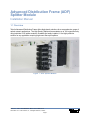
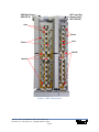
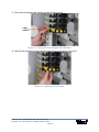
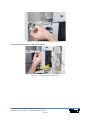
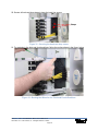
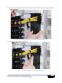
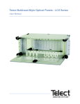
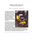
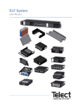
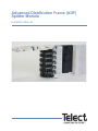
Advanced Distribution Frame (ADF)
Splitter Module
Installation Manual
Advanced Distribution Frame (ADF)
Splitter Module
Installation Manual 139253
Copyright 2010, Telect, Inc., All Rights Reserved
Telect and Connecting the Future are registered trademarks of Telect, Inc.
1730 N Madson St., Liberty Lake, Washington
Telect assumes no liability from the application or use of these products. Neither does Telect convey any
license under its patent rights nor the patent rights of others. This document and the products described
herein are subject to change without notice.
About Telect
Telect offers complete solutions for physical layer connectivity, power, equipment housing and other
network infrastructure equipment. From outside plant and central office to inside the home, Telect draws on
more than 25 years of experience to deliver leading edge product and service solutions. Telect is
committed to providing superior customer service and is capable of meeting the dynamic demands of
customer and industry requirements. This commitment to customer and industry excellence has positioned
Telect as a leading connectivity and power solution provider for the global communications industry.
Technical Support
E-mail: [email protected]
Phone: 888-821-4856 or 509-921-6161
Telect, Inc. • USA +1.509.926.6000 • Mexico +52.33.3836.37.52
www.telect.com • © 2010 Telect, Inc., All Rights Reserved, 139253
Page ii
Advanced Distribution Frame (ADF)
Splitter Module
Installation Manual
Table of Contents
1.1 Overview ................................................................................................................................ 1
1.2 Inspection ............................................................................................................................... 3
1.3 Installation .............................................................................................................................. 4
1.3.1 Installing the Chassis onto the Main Frame .................................................................. 4
1.3.2 Installing the Parking Lots ............................................................................................. 8
1.3.3 Installing Individual Splitter Modules into the Chassis .................................................. 9
List of Figures
Figure 1 - ADF Splitter Module .................................................................................................... 1
Figure 2 - ADF Components ........................................................................................................ 2
Figure 3 - Locating the Mounting Grooves ................................................................................... 4
Figure 4 - Locating the Mounting Pegs ........................................................................................ 5
Figure 5 - Seating the Pegs ......................................................................................................... 5
Figure 6 - Snapping the Tray and Cover into Position ................................................................. 6
Figure 7 - Securing the Module .................................................................................................... 7
Figure 8 - Removing the Hold Backs ........................................................................................... 8
Figure 9 - Installing Parking Lots ................................................................................................. 8
Figure 10 - Lifting off the Cover ................................................................................................... 9
Figure 11 - Lifting the Cover off the Pegs .................................................................................... 9
Figure 12 - Lifting off the Cover, continued ................................................................................ 10
Figure 13 - Releasing the Black Cable Routing Links ................................................................ 10
Figure 14 - Opening the Link Lids .............................................................................................. 11
Figure 15 - Opening the hook-and-loop straps .......................................................................... 11
Figure 16 - Installing the Splitter Modules .................................................................................. 12
Figure 17 - Threading the Legs .................................................................................................. 12
Figure 18 - Closing the Link Lids ............................................................................................... 13
Figure 19 - Closing the Link Lids, continued .............................................................................. 13
Figure 20 - Bring in Cables ........................................................................................................ 14
Figure 21 - Passing the Fibers ................................................................................................... 14
Telect, Inc. • USA +1.509.926.6000 • Mexico +52.33.3836.37.52
www.telect.com • © 2010 Telect, Inc., All Rights Reserved, 139253
Page iii
Figure 22 - Closing the Oval-shaped Cable Retainer ................................................................ 15
Figure 23 - Latching the Link Chain ........................................................................................... 15
Figure 24 - Routing the Fiber Cable ........................................................................................... 16
Figure 25 - Storing Excess Cable .............................................................................................. 16
Figure 26 - Installing Fiber Connectors ...................................................................................... 17
Figure 27 - Routing the Input Fiber ............................................................................................ 17
Figure 28 - Routing the Input Line ............................................................................................. 18
Figure 29 - Inserting the Connector ........................................................................................... 18
Figure 30 - Inserting the Connector, continued .......................................................................... 19
Figure 31 - Closing the Routing Area ......................................................................................... 19
Figure 32 - Securing the hook-and-loop straps .......................................................................... 20
Figure 33 - Routing the Wires for the Third and Fourth Positions .............................................. 20
Figure 34 - Routing the Wires for the Fifth and Sixth Positions ................................................. 21
Figure 35 - Inserting Fiber into the Routing Guide ..................................................................... 21
Figure 36 - Inserting Fiber into the Routing Guide, continued ................................................... 22
Telect, Inc. • USA +1.509.926.6000 • Mexico +52.33.3836.37.52
www.telect.com • © 2010 Telect, Inc., All Rights Reserved, 139253
Page iv
Advanced Distribution Frame (ADF)
Splitter Module
Installation Manual
1.1 Overview
Telect's Advanced Distribution Frame offers high-density solutions for a comprehensive range of
optical network applications. The High Density Splitter accommodates up to 192 output fibers by
using individual 1x32 splitter modules. Scalable and easily installed, it is a highly effective
solution for any application requiring high count fiber-optic splitters.
Figure 1 - ADF Splitter Module
Telect, Inc. • USA +1.509.926.6000 • Mexico +52.33.3836.37.52
www.telect.com • © 2010 Telect, Inc., All Rights Reserved, 139253
Page 1
ADF Main Frame
ADF-26F-XI
ADF Inter-Bay
Storage Panel
ADF-12INT-XI
Arcs
Posts
Arcs
Posts
Spools
Spools
Figure 2 - ADF Components
Telect, Inc. • USA +1.509.926.6000 • Mexico +52.33.3836.37.52
www.telect.com • © 2010 Telect, Inc., All Rights Reserved, 139253
Page 2
1.2 Inspection
Please read these instructions carefully before beginning installation. If you need assistance, call
Technical Support at 1-888-821-4856 (domestic calls), or 509-921-6161 (Option 2), or email us at
[email protected].
Inspect equipment after unpacking and compare it to the packing list.
Immediately report any shipping damage, defects, or missing parts to Telect at 1-800-551-4567.
Keep all documentation that comes with your shipment.
Telect is not liable for shipping damage. If the product is damaged, notify the carrier and call
Telect’s Customer Service Department at 1-800-551-4567 (domestic only) or 1-509-926-6000 for
further recourse.
NOTE: For service or warranty information, please visit telect.com website, or email inquiries to
[email protected] and click on the “Support” tab, or phone us at 800-551-4567 (domestic only)
or 509-926-6000.
Telect, Inc. • USA +1.509.926.6000 • Mexico +52.33.3836.37.52
www.telect.com • © 2010 Telect, Inc., All Rights Reserved, 139253
Page 3
1.3 Installation
!
ALERT
ALERT! Only qualified technicians may install and maintain this product.
Please prepare your work area and ADF frame by ensuring it is installed correctly. For
installation and preparation instructions, refer to the ADF User Manual, part number 119736-4,
which can be found on Telect.com. (Search using the document number 119736-4.) This
document was also included in the packaging for your ADF Frame.
1.3.1 Installing the Chassis onto the Main Frame
Procedure steps:
1. Locate the two grooves on the side of the ADF Frame in the position where you are planning
to mount the module.
Grooves
Figure 3 - Locating the Mounting Grooves
Telect, Inc. • USA +1.509.926.6000 • Mexico +52.33.3836.37.52
www.telect.com • © 2010 Telect, Inc., All Rights Reserved, 139253
Page 4
2. Locate the two mounting pegs on the rear of the module and position the mounting pegs over
the grooves.
Mounting Pegs
Figure 4 - Locating the Mounting Pegs
3. Carefully slide the module towards the rear of the frame, making sure that the pegs are
seated properly within the grooves.
Slide pegs
into the grooves
Figure 5 - Seating the Pegs
Telect, Inc. • USA +1.509.926.6000 • Mexico +52.33.3836.37.52
www.telect.com • © 2010 Telect, Inc., All Rights Reserved, 139253
Page 5
4. Once the module is seated properly, snap the top tray and front cover into position.
Figure 6 - Snapping the Tray and Cover into Position
Telect, Inc. • USA +1.509.926.6000 • Mexico +52.33.3836.37.52
www.telect.com • © 2010 Telect, Inc., All Rights Reserved, 139253
Page 6
5. Secure the module within the frame by installing the two mounting screws on the front of the
module using a large Phillips head screwdriver.
Figure 7 - Securing the Module
This procedure is complete.
Telect, Inc. • USA +1.509.926.6000 • Mexico +52.33.3836.37.52
www.telect.com • © 2010 Telect, Inc., All Rights Reserved, 139253
Page 7
1.3.2 Installing the Parking Lots
Procedure steps:
1. Remove the existing hold backs on the left side of the Interbay Storage Panel (ISP). Keep the
screws for installation of the parking lots.
Figure 8 - Removing the Hold Backs
2. Install the parking lot onto the Interbay Storage Panel (ISP) by tightening the four screws until
the parking lot is secure. You can install parking lots in all four available locations on the ISP if
desired.
Figure 9 - Installing Parking Lots
This procedure is complete.
Telect, Inc. • USA +1.509.926.6000 • Mexico +52.33.3836.37.52
www.telect.com • © 2010 Telect, Inc., All Rights Reserved, 139253
Page 8
1.3.3 Installing Individual Splitter Modules into the Chassis
Procedure steps:
1. Remove the cover on the outside of the module
by sliding it up off the pegs.
Figure 10 - Lifting off the Cover
2. Release the front of the cover and lift it up and off of each of the small pegs.
Pegs
Figure 11 - Lifting the Cover off the Pegs
Telect, Inc. • USA +1.509.926.6000 • Mexico +52.33.3836.37.52
www.telect.com • © 2010 Telect, Inc., All Rights Reserved, 139253
Page 9
Figure 12 - Lifting off the Cover, continued
3. Using the Telect Tray Removal Tool (part number 129461-1) or a screwdriver, release the
black cable routing links for module position #1 (the lowest position) by pushing the button on
the removal tool into the opening underneath the fixed link.
Fixed link
Step 2
Step 1
Step 3
Fixed link
Figure 13 - Releasing the Black Cable Routing Links
Telect, Inc. • USA +1.509.926.6000 • Mexico +52.33.3836.37.52
www.telect.com • © 2010 Telect, Inc., All Rights Reserved, 139253
Page 10
4. Open all link lids for the chain that you released.
Figure 14 - Opening the Link Lids
5. Make sure the hook-and-loop straps are open.
Figure 15 - Opening the hook-and-loop straps
Telect, Inc. • USA +1.509.926.6000 • Mexico +52.33.3836.37.52
www.telect.com • © 2010 Telect, Inc., All Rights Reserved, 139253
Page 11
6. Install the splitter module into the first position, the lowest position, closest to the frame.
Figure 16 - Installing the Splitter Modules
7. Thread all the yellow output legs through the opened links, reserving the blue input fiber off to
the side.
Figure 17 - Threading the Legs
Telect, Inc. • USA +1.509.926.6000 • Mexico +52.33.3836.37.52
www.telect.com • © 2010 Telect, Inc., All Rights Reserved, 139253
Page 12
8. Close all link lids, making sure to continue to support the cable bundle.
Figure 18 - Closing the Link Lids
Figure 19 - Closing the Link Lids, continued
Telect, Inc. • USA +1.509.926.6000 • Mexico +52.33.3836.37.52
www.telect.com • © 2010 Telect, Inc., All Rights Reserved, 139253
Page 13
9. Bring the cables to the inside of the frame.
Figure 20 - Bring in Cables
10. Making sure the oval-shaped cable retainer is open, pass the fibers above and below the
oval-shaped cable retainer.
Cable
retainer
Figure 21 - Passing the Fibers
Telect, Inc. • USA +1.509.926.6000 • Mexico +52.33.3836.37.52
www.telect.com • © 2010 Telect, Inc., All Rights Reserved, 139253
Page 14
11. Close the oval-shaped cable retainer to keep all fibers captive.
Cable
retainer
Figure 22 - Closing the Oval-shaped Cable Retainer
12. Latch the link chain back into the location from which you previously removed it.
Figure 23 - Latching the Link Chain
Telect, Inc. • USA +1.509.926.6000 • Mexico +52.33.3836.37.52
www.telect.com • © 2010 Telect, Inc., All Rights Reserved, 139253
Page 15
13. Route the fiber cable down the ADF and over to the Interbay Storage Panel (ISP) where the
parking lots are installed.
Figure 24 - Routing the Fiber Cable
14. Use the center storage on the ISP to store excess cable as needed to allow access to the
parking lot locations.
Figure 25 - Storing Excess Cable
Telect, Inc. • USA +1.509.926.6000 • Mexico +52.33.3836.37.52
www.telect.com • © 2010 Telect, Inc., All Rights Reserved, 139253
Page 16
15. Install fiber connectors into the parking lot to store until needed on the frame.
Figure 26 - Installing Fiber Connectors
16. Route the blue input fiber by threading the fiber below the yellow output fibers.
Figure 27 - Routing the Input Fiber
Telect, Inc. • USA +1.509.926.6000 • Mexico +52.33.3836.37.52
www.telect.com • © 2010 Telect, Inc., All Rights Reserved, 139253
Page 17
17. Route the input line through the black routing guide, as shown below.
Black
Routing
Guide
Figure 28 - Routing the Input Line
18. Insert the connector into the first adapter in the tray.
Figure 29 - Inserting the Connector
Telect, Inc. • USA +1.509.926.6000 • Mexico +52.33.3836.37.52
www.telect.com • © 2010 Telect, Inc., All Rights Reserved, 139253
Page 18
Figure 30 - Inserting the Connector, continued
19. Close the routing area on the side of the tray.
Figure 31 - Closing the Routing Area
Telect, Inc. • USA +1.509.926.6000 • Mexico +52.33.3836.37.52
www.telect.com • © 2010 Telect, Inc., All Rights Reserved, 139253
Page 19
20. Secure all hook-and-loop straps to keep the input line secure.
Straps
Figure 32 - Securing the hook-and-loop straps
21. For modules in the third and fourth positions, follow the routing shown in the figure, below.
Figure 33 - Routing the Wires for the Third and Fourth Positions
Telect, Inc. • USA +1.509.926.6000 • Mexico +52.33.3836.37.52
www.telect.com • © 2010 Telect, Inc., All Rights Reserved, 139253
Page 20
22. For modules in the fifth and sixth position, place a loop in the fiber before routing, as shown in
the following figure.
Figure 34 - Routing the Wires for the Fifth and Sixth Positions
23. Gently place fiber in the routing guide.
Figure 35 - Inserting Fiber into the Routing Guide
Telect, Inc. • USA +1.509.926.6000 • Mexico +52.33.3836.37.52
www.telect.com • © 2010 Telect, Inc., All Rights Reserved, 139253
Page 21
Figure 36 - Inserting Fiber into the Routing Guide, continued
This procedure is complete.
To order, or for more information on the Advanced Distribution Frame (ADF), please contact your
Telect Sales Representative or visit Telect.com.
Telect, Inc. • USA +1.509.926.6000 • Mexico +52.33.3836.37.52
www.telect.com • © 2010 Telect, Inc., All Rights Reserved, 139253
Page 22