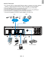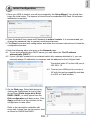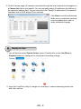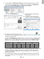
1
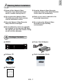
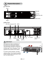
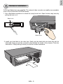
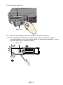
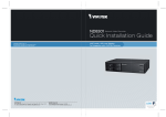
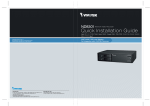
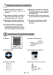
ND8301 Network Video Recorder
Quick Installation Guide
VAST inside • HD Local Display •
Full Integration with VIVOTEK Cameras
P/N:625017300G Rev. 1.0
All specifications are subject to change without notice.
Copyright c 2012 VIVOTEK INC. All rights reserved.
VIVOTEK INC.
6F, No.192, Lien-Cheng Rd., Chung-Ho, New Taipei City, 235, Taiwan, R.O.C.
|T: +886-2-82455282| F: +886-2-82455532| E: [email protected]
VIVOTEK USA, INC.
2050 Ringwood Avenue, San Jose, CA 95131
|T: 408-773-8686| F: 408-773-8298| E: [email protected]
English
Warning Before Installation
Power off the Network Video
Recorder if you detect abnormal
smell or smoke coming from it.
Keep the Network Video Recorder
away from water. If the Video Recorder
is wet, power off immediately.
Do not place the Network Video
Recorder around the heat sources,
such as television or oven.
Refer to your user's manual for the
operating temperature.
Keep the Network Video Recorder
away from direct sunlight.
Do not place the Network Video
Recorder in high humidity
environments.
Do not attempt to remove or uninstall
the software on the mounted IDE flash.
Nor should you open the chassis. Doing
so will void our warranty.
1
Package Contents
ND8301
Power Cord & Adaptor
Software CD
Quick Installation Guide
5 1 0 0 0 02 2 1 G
Warranty Card
EN - 1
2
Physical Description
Front View
Disk 1
HDD LED
Power
button & LED
Reset button
Disk 2
Rear View
RS-232 (reserved) LAN WAN
VGA
Line In
USB2
Line Out DC Power
eSATA
combo
USB1
MIC-In
combo
Fan exhaust
outlet
IMPORTANT:
It is important to leave a clearance of
15cm to the rear side of the chassis.
The clearance is required to ensure an
adequate airflow through the chassis to
ventilate heat. A 5cm clearance is also
required on both sides of the chassis.
15cm
5cm
To ensure normal operation, maintain
ambient airflow. Do not block the airflow
around chassis such as placing the system in a closed cabinet.
EN - 2
5cm
5cm
English
3
Hardware Installation
SATA hard disk(s) are user-supplied. The network video recorder can readily accommodate
most of the off-the-shelf SATA hard drives.
1.Use a flat-blade screwdriver to unlock the rotary bezel lock. Open the drive bay bezel by
pulling the lever on it.
Bezel Lock
Bezel Lever
2.Install your hard disk to the drive bay. Gently put the hard disk into drive bay with its
label side facing up and the connector side towards the inside of the chassis. Push the
hard disk in. Stop pushing it when you feel the contact resistance.
EN - 3
3.Close the drive bay bezel.
HDD
Bezel Lever
4.4-1. P
ress on the left edge of the drive bay bezel to snap it into place.
4-2. U
se a flat-blade screwdriver to turn the bezel lock to the “locked” position.
You should always lock the drive bezel when the drive bay is populated. This ensures the hard drive is securely installed.
Bezel Lock
2
1
EN - 4
English
Interface Connections
1 & 2. Connect CAT5 or better-quality Ethernet cables to cameras via a local, switched
network, or clients through the Internet. Refer to next page for more information.
3.Connect the DB15 VGA port to a monitor (with resolutions up to 1920x1080).
4.Connect USB devices such as keyboard and mouse.
5.If an external eSATA storage enclosure is available, connect it to the eSATA port.
6.Connect speakers or microphone to the phone-jack connectors.
7.Connect the supplied 100-240V DC power adaptor. (50~60Hz, 5A)
LAN
WAN
Router
Internet
LAN
1
3
2
4
VGA
5
6
Audio devices
USB devices
External enclosure
EN - 5
7
DC power adaptor
4
Network Deployment
1.Connect the supplied power adapter to a power outlet.
2.Connect network cameras to the NVR’s LAN ports.
3.If you want to access NVR over the Internet, connect the NVR to the Internet via the
WAN port. A web console can be established from a remote PC by keying http://<public
IP>:3454 in a browser’s URL address field. However, port forwarding on the router for
the TCP port will be necessary.
4.Push the power button to run the NVR.
Clients
Router
Internet
Router
Switch
Wireless AP / Router
Default Fixed IP:
192.168.1.10
LAN
WAN
Default: DHCP
NOTE:
The LAN and WAN ports can be configured into the same or different subnets.
If you have cameras connected via the WAN port, make sure the WAN port
acquires an IP address from a DHCP server on router or AP. If not, the cameras
detected through the WAN port will use the default IPs, e.g., 169.254.xx.xx, and the
LiveClient software will not be able to detect their presence.
EN - 6
English
5
Initial Configuration
1.Once your NVR is started, you will be prompted by the Setup Wizard. You should then
begin the initial setup. The system is booted from an embedded IDE flash. No software
installation is required.
2.Enter the default User name and Password as admin & admin. It is recommended you
change the password later to prevent unauthorized access.
3.Click Next to proceed with configuration and follow the onscreen instructions to finish the
configuration process.
4.Note the following when you move to the Network page:
4-1. If your local network has a DHCP server, you can select the "Get IP address
automatically (DHCP)."
4-2. If your LAN port connects to an isolated switch with cameras attached to it, you can
manually assign IP addresses to cameras, and the address for the LAN port itself.
The default static IP for the LAN port is
192.168.1.10.
4-3. Connect your WAN port to a router or
AP with the routing capability and then
to a DSL or Cable modem.
5.On the Disk page, Select disk drives by
clicking the checkboxes in front of disk
drives.Select Build single disk, Build
RAID0, RAID1, or other option from the
Disk configuration pull-down menu. Click
Apply and wait for a few minutes for the
configuration to take effect.
Refer to the description available with
every disk volume type on the screen, such
as those for RAID0 and RAID1.
EN - 7
6.On the Camera page, all cameras connected through the local network should appear on
a Camera list after a brief search. You can manually assign IP addresses by clicking on
the cameras' address field. You can also select the "Assign IP addresses to all cameras"
checkbox and let NVR assign IPs to cameras.
Click Next to end the initial setup.
Make sure you have the cameras'
access credentials in order to
make individual changes.
6
Ready to Use
1.You will then be at the Control Center screen. Double-click on the LiveClient or
Playback buttons to configure live viewing and recording settings.
2.Open the LiveClient utility to change live view layout, camera streaming frame rate,
and other options.
EN - 8
3-3. Select cameras by clicking their
checkboxes.
3-4.Click OK, return to the previous
window, and click the Insert button.
3-2. Click on the Search button.
4. It is important to ensure that the live vie
wing and recording configuration does not
exceed the system's limits:
In terms of local display, the default stream 1 for live view can be configured with a
resolution up to Full HD 30fps. Stream 1 is also a source for continuous recording.
Make sure your cameras' stream 1 resolution does not exceed 1080P at 30fps.
Compression
Resolution
Frame rate
Bit rate
No. of streams
MPEG4
CIF
30fps
512Kbps
12
VGA
30fps
1Mbps
5
H.264
1080P
30fps
6Mbps
2
CIF
30fps
512Kbps
7
VGA
30fps
1Mbps
3
1080P
30fps
6Mbps
1
The NVR supports Auto Stream Size, which automatically adjusts streaming display
for efficient leverage of system resources. If you disable the Auto Stream Size
function and manually configure your stream settings, you must comply with the
limitations listed above.
5. After inserting your cameras, you can start dragging cameras into view cells and
proceeding with the rest of the configuration. Refer to your User Manual for more
information.
EN - 9
English
3. 3-1. By default, the Batch Insert Cameras window will prompt for you to recruit
cameras into your configuration. If it does not, you can enter the Configuration
menu, select Camera Management > Batch Insert Cameras.
ND8301 Network Video Recorder
Quick Installation Guide
VAST inside • HD Local Display •
Full Integration with VIVOTEK Cameras
P/N:625017300G Rev. 1.0
All specifications are subject to change without notice.
Copyright c 2012 VIVOTEK INC. All rights reserved.
VIVOTEK INC.
6F, No.192, Lien-Cheng Rd., Chung-Ho, New Taipei City, 235, Taiwan, R.O.C.
|T: +886-2-82455282| F: +886-2-82455532| E: [email protected]
VIVOTEK USA, INC.
2050 Ringwood Avenue, San Jose, CA 95131
|T: 408-773-8686| F: 408-773-8298| E: [email protected]