1
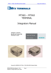
MLB-G1101 Wireless Terminal User Manual MLiS Basic Wireless Terminal 2G / 3G Model Number: MLB-G1101 MLB-G1101 WIRELESS TERMINAL User Guide 1 Rev 1.1 Information provided by Schmidt & Co., (HK) Ltd, (herein known as ‘the company’), is believed to be accurate and reliable. However, the company assumes no responsibility for its use, nor any infringement of patents or other rights of third parties, which may result from its use. No license is granted by implication or otherwise under any patent rights of the company other than for circuitry embodied in the company’s products. The company reserves the right to change the circuitry and specifications at any time without notice. This document is subject to change without notice. No part of this document may be reproduced or transmitted in any form or by any means, electronic or mechanical, including but not limited to photocopying, recording, transmitting via fax and/or modem devices, scanning, and/or information storage and retrieval systems for any purpose without the expressed written consent of the company. WARNING: The MLiS GSM wireless terminal is a RF product intended for interfacing and operating with a host device. Local relevant RF regulations such as allowed frequencies and usage in commercial flights must be observed. Safety instructions must be included in the manuals of the host device. Schmidt & Co., (HK) Ltd assumes NO liability for customers, who fail to comply with these precautions. Service and Support TBA Download Information TBA MLB-G1101 WIRELESS TERMINAL User Guide 2 Rev 1.1 Revision History Version 1.0 1.1 1.2 1.3 Date Mar 2014 April 2014 May 2015 Sep. 2015 MLB-G1101 WIRELESS TERMINAL User Guide Description 1st Release 2nd Release 3rd Release 4th Release 3 Rev 1.1 CONTENTS 1 INTRODUCTION ............................................................................................................................ 6 1.1 Description ............................................................................................................................. 6 1.2 Highlights ............................................................................................................................... 6 1.3 Functional Block diagram ....................................................................................................... 8 1.4 Main Features and Services ................................................................................................... 9 1.4.1 Operating Modes ................................................................................................................ 9 1.4.2 wireless terminal Features and Electrical Specifications ................................................... 10 1.5 2 3 4 Precautions .......................................................................................................................... 11 MECHANICAL DESCRIPTION ..................................................................................................... 12 2.1 Overview .............................................................................................................................. 12 2.2 Dimensions .......................................................................................................................... 12 ELECTRICAL INTERFACE DESCRIPTIONS ............................................................................... 13 3.1 Right side view (DB9 connector) .......................................................................................... 13 3.2 Left side view (DC Jack & Industry connector)...................................................................... 14 3.3 Frond view (Antenna & LED ) ............................................................................................... 15 3.4 SIM card holder .................................................................................................................... 16 3.5 Demo process .................................................................................................................... 16 OPERATING NOTE...................................................................................................................... 30 4.1 Power on the Modem ........................................................................................................... 30 4.2 Reset to default .................................................................................................................... 30 4.3 External input x2................................................................................................................... 30 4.4 External Relay x1 ................................................................................................................. 30 4.5 DB9 Connector ..................................................................................................................... 30 4.6 Install SIM card..................................................................................................................... 30 MLB-G1101 WIRELESS TERMINAL User Guide 4 Rev 1.1 5 SCHMIDT Protocol ....................................................................................................................... 30 6 SALES CONTACT ........................................................................................................................ 31 7 ORDERING INFORMATION......................................................................................................... 32 List of Figures Figure 1: Functional Block Diagram for MLB-G1101 .............................................................................. 8 Figure 2: Chassis Dimension for MLB-G1101 ...................................................................................... 12 Figure 3:RS232/RS422/RS485 for MLB-G1101 ................................................................................... 13 Figure 4: DC and Industry connector for MLB-G1101 .......................................................................... 14 Figure 5: Antenna Connector for MLB-G1101 ...................................................................................... 15 Figure 6: SIM Card Holder for MLB-G1101 .......................................................................................... 16 List of Tables Table 1: Operating Modes ..................................................................................................................... 9 Table 2: Features and Specifications ................................................................................................... 10 Table 3: Chassis Dimensions and Mechanical Description for MLB-G1101 ......................................... 12 Table 4: DB9 pins define for MLB-G1101............................................................................................. 13 Table 5: Interfaces and Indicators Description of MLB-G1101 ............................................................. 14 Table 6: LED functions of MLB-G1101................................................................................................. 15 MLB-G1101 WIRELESS TERMINAL User Guide 5 Rev 1.1 1 INTRODUCTION 1.1 Description The MLiS MLB-G1101 is a Dual Band 2G/3G wireless terminal designed for RS232/RS422/RS485 communication over TCP/IP via any readily available 2G/3G carrier network. Overall, it is more cost and time effective to use remote solutions to combine Machine to Machine over diverse locations without having first to establish and invest in a huge complex network. The MLB-G1101 wireless terminal uses the DB9 Connector to provide data communication interface and the DC jack to provide power input. LEDs are used to indicate the status of the wireless terminal. The MLB-G1101 wireless terminal can be used to provide a wireless communication link to many applications, including metering, fleet and asset management, vending, security and alarm monitoring, e-maintenance and other telemetry applications. 1.2 Highlights Interface DC jack Connector for power DB9 connector(Female) SMA Female Connector (GSM antenna connector) SIM card reader 1 * relay 2 * I/O pins General Features • • • • • • • • • Frequency Range : EU GSM/GPRS/EDGE: 900/1800MHz&UMTS/HSPA+: 900/2100MHz US GSM/GPRS/EDGE: 850/1900MHz&UMTS/HSPA+: 850/1900MHz Protocol Stack : TCP/UDP Power Supply Input : 5 to 32 VDC Relative Humidity : 90% MAX. Operation Temperature : -40°C ~75°C Switch Off Protection : +90°C Dimensions (L) x (W) x (H) : 119.5 x 89 x 26.9 mm (excluding connectors) Weight : 200g Casing Material : Metal MLB-G1101 WIRELESS TERMINAL User Guide 6 Rev 1.1 Data Transmission • • • • • GPRS : Multi-slot Class 12, Mobile Station Class B. EDGE : Multi-slot Class 12 CSD : -9.6kbps, non-transparent, V.110 • • Relay : 1 output with current carrying capacity of 1A @ 24 VDC • • • • • ESD Protection : 15KV SMS : MT, MO, Cell Broadcast, Text and PDU mode. Serial Parameter : – Data Bits : 5, 6, 7, 8 – Stop Bits : 1, 1, 5, 2 – Parity : None, Even, Odd, Space, Mark – Flow Control : RTS/CTS, DTR/DSR – Baud-rate : 1200~230400 selectable – Serial signals : TxD, RxD, RTS, CTS, DTR, DSR, DCD, RST(reset circuit), GND Digital Inputs : 2 electrically isolated inputs: – +13 to 30V for state “1” (On) – +3 to -30V for state “0” (Off) Data Buffering : 1M` Data Delimiter : Yes Data Length Packing : Yes MCCP/MCCU : Yes – API : MLiS Cellular Control Protocol (=MCCP) – Utility : MLiS Cellular Control Utility (=MCCU) MLB-G1101 WIRELESS TERMINAL User Guide 7 Rev 1.1 1.3 Functional Block diagram DB9 Figure 1: Functional Block Diagram for MLB-G1101 The MLB-G1101 consists of a fully certified (CE /NCC approved) GSM/GPRS engine, SIM card holder and power regulator. The wireless terminal is supplied with power via the DC jack. The remaining DB9 connector is used for data communications. The SMA female connector provides the air interface to an external 50 ohm antenna specified for the correct frequency band. MLB-G1101 WIRELESS TERMINAL User Guide 8 Rev 1.1 1.4 Main Features and Services The MLB-G1101 performs a set of telecom services (TS) according to GSM standard phase 2+, ETSI and ITU-T. The services and functions of the MLB-G1101 are implemented by issuing customized applications embedded on the device, or by AT commands issued internally, or over the RJ45 to RS232 serial interface. 1.4.1 Operating Modes The table below briefly summarizes the various operating modes referred to in the following chapters. Normal operation POWER DOWN Airplane mode GSM / GPRS SLEEP Various power save modes set with AT+CFUN command. Software is active to minimum extent. If the module was registered to the GSM network in IDLE mode, it is registered and paging with the BTS in SLEEP mode, too. Power saving can be chosen at different levels: The NONCYCLIC SLEEP mode (AT+CFUN=0) disables the AT interface. The CYCLIC SLEEP modes AT+CFUN=7 and 9 alternately activate and deactivate the AT interfaces to allow permanent access to all AT commands. GSM IDLE Software is active. Once registered to the GSM network, paging with BTS is carried out. The module is ready to send and receive. GPRS IDLE Module is ready for GPRS data transfer, but no data is currently sent or received. Power consumption depends on network settings and GPRS configuration (e.g. multi-slot settings). GPRS DATA GPRS data transfer in progress. Power consumption depends on network settings (e.g. power control level), uplink / downlink data rates, GPRS configuration (e.g. used multi-slot settings) and reduction of maximum output power. Normal shutdown after sending the AT^SMSO command. Only a voltage regulator is active for powering the RTC. Software is not active. Interfaces are not accessible. Operating voltage (connected to BATT+) remains applied. Airplane mode shuts down the radio part of the module, causes the module to log off from the GSM/GPRS network and disables all AT commands whose execution requires a radio connection. Airplane mode can be controlled by using the AT commands AT^SCFG and AT+CALA: • With AT^SCFG=MEopMode/Airplane/OnStart the module can be configured to enter the Airplane mode each time when switched on or reset. • The parameter AT^SCFG=MEopMode/Airplane can be used to switch back and forth between Normal mode and Airplane mode any time during operation. • Setting an alarm time with AT+CALA followed by AT^SMSO wakes the module up into Airplane mode at the scheduled time. Table 1: Operating Modes MLB-G1101 WIRELESS TERMINAL User Guide 9 Rev 1.1 1.4.2 Wireless Terminal Features and Electrical Specifications Table 2: Features and Specifications S/N 1 Feature Frequency Bands Specifications EU GSM/GPRS/EDGE: 900/1800MHz and UMTS/HSPA+: 900/2100MHz US GSM/GPRS/EDGE: 850/1900MHz and UMTS/HSPA+: 850/1900MHz 2 RF Output Power 3 4 5 GSM Phase Power Supply Power Consumption 6 7 Operating Temperature Data Transfer 8 SMS 9 10 AT Commands TCP/IP Stack 11 Serial Interface 12 SIM Interface MLB-G1101 WIRELESS TERMINAL User Guide Class 4 (+33dBm ±2dB) for EGSM850 (quad band only) Class 4 (+33dBm ±2dB) for EGSM900 Class 1 (+30dBm ±2dB) for GSM1800 Class 1 (+30dBm ±2dB) for GSM1900 (quad band only) Release 99 5 o 32 VDC - DATA mode : GPRS 1TX, 4RX 180mA GSM 850/EGSM 900 145mA GSM 1800/1900 - DATA mode : GPRS 2TX, 3RX 330mA GSM 850/EGSM 900 260mA GSM 1800/1900 Normal operation: -40°C to +75°C GPRS Multi-slot Class 12 max 85.6kbps (Downlink and Uplink) Full PBCCH Support Mobile Station Class B Coding Scheme 1~4 PPP stack CSD V.110, RLP, non-transparent @2.4, 4.8, 9.6 & 14.4kbps USSD PPP-stack for GPRS data transfer Point-to-Point MT and MO Cell Broadcast Text and PDU Mode Storage: SIM Card plus 25 SMS locations in mobile equipment Transmission of SMS alternatively over CSD or GPRS. Preferred mode can be user defined. AT-Hayes 3GPP TS 27.007, TS 27.005 Access by AT Commands Internet Services include TCP, UDP, DB9 connector 8-wire Modem Interface with status and control lines, unbalanced, asynchronous Fixed bit rate: 1,200bps to 230,400bps Flow Control: Hardware RTS0/CTS0 and Software XON/OFF Multiplex ability according to GSM 07.10 Multiplexer Protocol SIM Card Slot 10 Rev 1.1 S/N Feature 13 14 15 Antenna Software Reset RoHs 1.5 Specifications Supports SIM Cards: +3V and +1.8V 50 ohms via External SMA Connector Orderly shutdown and Reset by AT Command (AT^SMSO) All hardware components are fully compliant with the EU RoHs directive 2002/95/EC Exception: MLB55IN Precautions The MLB-G1101 wireless terminal is designed for indoor use only. For outdoor use it has to be integrated into a weatherproof enclosure. Do not exceed the environmental and electrical limits as specified in the user manual. MLB-G1101 WIRELESS TERMINAL User Guide 11 Rev 1.1 2 MECHANICAL DESCRIPTION 2.1 Overview The pictures below show the mechanical design of the wireless terminal along with the positions of the different connectors. 2.2 Dimensions Figure 2: Chassis Dimension for MLB-G1101 S/N Parameter Value 1 Height (H) 26.9mm 2 Length (L) 119.5mm 3 Width (W) 89.0mm 4 Weight 200g 5 Chassis Material Metal Table 3: Chassis Dimensions and Mechanical Description for MLB-G1101 MLB-G1101 WIRELESS TERMINAL User Guide 12 Rev 1.1 3 ELECTRICAL INTERFACE DESCRIPTIONS 3.1 Right side view (DB9 connector) Figure 3:RS232/RS422/RS485 for MLB-G1101 The table below defines the RS232/RS422/RS485 pin configuration on the wireless terminal Table 4: DB9 pins define for MLB-G1101 MLB-G1101 WIRELESS TERMINAL User Guide 13 Rev 1.1 3.2 Left side view (DC Jack & Industry connector) Figure 4: DC and Industry connector for MLB-G1101 The interfaces and indicators for MLB-G1101 are as follows: Name Description DC DC PWR(V+,V-) Function Input Power:+5V~+32V • • • • Terminal Block Relay Power:+5V~+32V Pin #1 is V+ Pin #2 is VWhen use DC for input, the output power of TB is same as input power Do Not use DC & PWR to be the input power at the same time, it may cause damage to the equipment. External Relay:max+40V • • • • • • • • • • • I1:external signal +12V~+48V COM_1:common grand Pin #5 is + Pin #6 is I2:external signal,+12V~+48V DI2(I2,COM_2) COM_2:comman grand Pin #7 is + Pin #8 is Pin #7 is + Pin #8 is 1-click to reboot G1101. Reset Double click to set G1101 into configuration mode. Long press over 5 seconds to reset G1101 to default. Table 5: Interfaces and Indicators Description of MLB-G1101 DI1(I1,COM_1) Pin #5 is + Pin #6 is - Reset Input MLB-G1101 WIRELESS TERMINAL User Guide 14 Rev 1.1 3.3 Frond view (Antenna & LED) Figure 5: Antenna Connector for MLB-G1101 For optimum RF performance, the MLiS wireless terminal has to be connected to an external RF antenna matched to 50ohms. Please use a SMA Male connection for the wireless terminal. The functions of LED are indicated on the table below. Item 1 2 3 4 5 6 7 8 Description Power 3G Ready Fault Net SIMerr Tx Rx MLB-G1101 WIRELESS TERMINAL User Guide Function Power on indication 3G status indication Function working indication Occur error Builds connection SIM card error indication UART transmit indication UART Receive indication Table 6: LED functions of MLB-G1101 15 Rev 1.1 3.4 SIM card holder In the bottom, The MLB-G1101 wireless terminal is provided with a SIM card reader designed for 1.8V and 3V SIM cards. It is the flip-up type which can be locked. It can be accessed through removing the battery cover as shown below. Figure 6: SIM Card Holder for MLB-G1101 Be sure to power off the modem when user replaces the SIM card. Otherwise it may cause damage to the equipment. The MLB-G1101 fully operates when inserting a SIM card. Some MLB-G1101 functionality may be lost if user try to operate the wireless terminal without a SIM card. MLB-G1101 WIRELESS TERMINAL User Guide 16 Rev 1.1 3.5 Getting Started HW installation Step 1:Please insert SIM card into SIM card holder as follows Be sure to power off the modem when user replaces the SIM card. Otherwise it may cause damage to the equipment. Step 2:Please connect serial port to device as following Pinouts MLB-G1101 WIRELESS TERMINAL User Guide 17 Rev 1.1 Step 3: Please connect power supplier with 5~32 VDC, then boot up. The LED will light up when G1101 ready. Step 4:After plug-in power adapter. The wireless terminal is usually fully operational within 30 seconds, after powering it up. Depending on the signal strength of the network in the area, logging into a network may take longer and is outside the control of the wireless terminal. The device is ready after LED of signal is lighted. Then user can operate it. Step 5: When user use the MCCU (MLiS Cellular Configuration Utility) to configure MLB-G1101, please refer the connection as below: MLB-G1101 WIRELESS TERMINAL User Guide 18 Rev 1.1 SW Installation Preliminary work: Power on G1101 and use USB-to-RS232 cable to connect to G1101 & PC. Step 1:Open MCCU (MLiS Cellular Configuration Utility) Step 2:The main window of MCCU launch. Figure 1: MLB-G1101 wireless terminal test tool MLB-G1101 WIRELESS TERMINAL User Guide 19 Rev 1.1 Basic Information The Basic Information page summarizes the current settings of MLB-G1101. Item Model FW Version Shows the model user connected. Current firmware version. SIM Card The status of SIM Card. Operator Telecoms Get Info Click it to reload the basic info. MLB-G1101 WIRELESS TERMINAL User Guide 20 Rev 1.1 SMS Configuration MLB-G1101 support events alert through SMS. Item SMS Admin Phone no. format Set the phone no. to be the Admin. Then user uses this phone to send SMS to modify the settings of MLB-G1101. Input phone no. with country code. How to Send? 1. RESET (1). RESET 2. TCPIPPORT+(space)+Profile Index (0 ~ 4)+ , + IP:Port+ , (2). Change IP & Port. For example: +886911222333 Ex 1 : TCPIPPORT 1, 192.168.1.1:3000, (TCP socket, Profile index = 1, IP = 192.168.1.1:3000) Ex 2 : TRANIPPORT 0, 192.168.2.2:6000, (Transparent mode, Profile index = 0, IP = 192.168.2.2:6000) Ex 3 : UDPIPPORT 4, 192.168.3.3:20000, (UDP mode, Profile index = 4, IP = 192.168.3.3:2000) Input phone no. with country code Reboot event Tick the check box then input the phone number. When the reboot event occurred, G1101 will send SMS to the phone number user set. GPRS off-line Tick the check box then input the phone number. When the GPRS off-line event occurred, G1101 will send SMS to the phone number user set. Input phone no. with country code. MLB-G1101 WIRELESS TERMINAL User Guide 21 For example: +886911222333. For example: +886911222333. Rev 1.1 DIO1 changed DIO2 changed Relay changed Tick the check box then input the phone number. When the DIO1 event occurred, G1101 will send SMS to the phone number user set. Input phone no. with country code. Tick the check box then input the phone number. When the DIO2 event occurred, G1101 will send SMS to the phone number user set. Input phone no. with country code. Tick the check box then input the phone number. When the relay event occurred, G1101 will send SMS to the phone number user set. Input phone no. with country code. MLB-G1101 WIRELESS TERMINAL User Guide 22 For example: +886911222333. For example: +886911222333. For example: +886911222333. Rev 1.1 Option Set variables and Get Relay/DIO status in Option page. Item Get DIO1 Click to get the status of DIO1 Get DIO2 Click to get the status of DIO2 Relay Send to SMS/Send to Server Click ON/OFF to enable/disable relay Select the receiver (SMS or Server) when the status of DIO changed. Serial Switch Select RS232/422/485 mode by drop-down list. Set Baud-rate Set different baud-rate by drop-down list. Retry Time Time Interval MLB-G1101 WIRELESS TERMINAL User Guide Set the retry times when connection interrupts. The interval between two retries. 23 Rev 1.1 Heartbeat Heartbeat String Send to Main/Send to all MLB-G1101 WIRELESS TERMINAL User Guide Set the transmission frequency of heartbeat. Ex. If user sets 60 seconds, the heartbeat will send every 60 seconds. Set the string of heartbeat. Select the Heartbeat receiver. (Main server only or all) 24 Rev 1.1 Step 3:Select the Operation mode by drop-down list, then the related setting page displayed. Operation mode Transparent Mode APN: Please confirm with carriers. ID: Set ID.(It supports up to 15 characters) IP-1: Single IP. Port: Set the port. Packing Mode/Fast Mode: Select the Mode under Transparent. Those modes are used for different cases. Please refer Modes table. Notice: Other functions will be disabled when Fast Mode is enabled. Reset to default to configure when the wireless terminal runs with Fast Mode. MLB-G1101 WIRELESS TERMINAL User Guide 25 Rev 1.1 Socket TCP Mode APN: Please confirm with carriers. ID: Set ID.(It supports up to 15 characters) 1-IP~5-IP: Multiple IP. Port: Set the port. Notice: When the multiple IP function is enabled with large data transmission, the transmission performance will be affected. Socket UDP Mode APN: Please confirm with carriers. MLB-G1101 WIRELESS TERMINAL User Guide 26 Rev 1.1 ID: Set ID.(It supports up to 15 characters) IP-1~IP-3: Multiple IP to transfer. Notice: When the multiple IP function is enabled with large data transmission, the transmission performance will be affected. SMS Mode Mobile: Set the mobile number user receives SMS. Send Box: Input SMS text. AT Command Click to switch to AT command mode. MLB-G1101 WIRELESS TERMINAL User Guide 27 Rev 1.1 Modes: TCP/UDP Transparent Transparent Client Mode Packing Mode Fast Mode 5 1 1 2~5M 7M 10M Functions Fully Support Fully Support Transmission Only Packing TCP packing Stream Stream Connection Speed (Base on baud-rate 115200) Notice: In common, we suggest user to use TCP/UDP mode. MLB-G1101 WIRELESS TERMINAL User Guide 28 Rev 1.1 Step 4:Click Apply to save settings to G1101. • When applying the setting, make sure the RS232 cable is well connected. • If the cable is loose during the applying, please long press the “Reset” button to reset G1101 to default. Then apply the setting again. Step 5:Settings are saved and re-plug the power. [Note]: This is a real operation for reference. The user may input different parameters accordingly • If G1101 is not running with 115200 baud-rate and user want to re-configure it, please double click the reset button to enter configuration mode (115200, N81). (Refer 3.2 Table5) MLB-G1101 WIRELESS TERMINAL User Guide 29 Rev 1.1 4 OPERATING NOTE 4.1 Power on the Modem After plugin the power adapter, the modem is usually fully operational within 4 seconds, after powering it up. Depending on the signal strength of the network in the area, logging into a network may take longer and is outside the control of the modem. 4.2 Reset to default Press reset button, it will be reset to default. All of temporary data buffer will be clear. 4.3 External input x2 External signal input source, positive signal are DI1 and DI2, negative signal are COM_1 are COM_2. Power input range is +12V~+48V, it will be determined as positive. It can be used for alert. 4.4 External Relay x1 Non positive and negative signal relay output, maximum power input voltage range is +48V. It can be used for beeper. 4.5 DB9 Connector The RS-232/422/485 connector is DB9 male type, please refer to table 4 4.6 Install SIM card Please turn to back view, screw open the cover, then user will see SIM card holder. Please use SIM card faces to PCB board and put it into holder, please screw the cover back. (Please refer to Figure 6) MLB-G1101 WIRELESS TERMINAL User Guide 30 Rev 1.1 SALES CONTACT Website : www.schmidt.com Singapore Malaysia Shenzhen, China Taiwan Thailand Schmidt Electronics (S.E.A.) Pte Ltd 158 Kallang Way #06-10, Performance Building Singapore 349245 T (65) 6272-7233 F (65) 6273-4750 E [email protected] Schmidt Electronics (Malaysia) Sdn Bhd Suite G2, Ground Floor, Wisma Tecna, No. 18A, Lot 318, Jalan 51A/223, 46100 Petaling Jaya, Selangor Darul Ehsan, Malaysia T (60-3) 7957-1080 F (60-3) 7956-8670 E [email protected] Schmidt & Co., (China) Ltd. Shenzhen Branch Schmidt (Shenzhen) Co., Ltd 3/F Unit E, International Culture Building, Fu Tian Road, Shenzhen 518033 T (86-755) 8376-0232 F (86-755) 8376-0025 E [email protected] Schmidt & Co., (Hong Kong) Limited 5/F, 139 Song Jiang Road, Taipei 104, Taiwan T (886-2) 2502-5095 F (886-2) 2502-6717 E [email protected] Schmidt Electronics (Thailand) Ltd 252/97 (B), 19th Fl., Tower B, Muang Thai-Phatra Complex Building, Ratchadaphisek Rd., Huaykwang Subdistrict, Huaykwang District Bangkok 10310 Thailand T (66-0) 2693-3445 F (66-0) 2693-3448 E [email protected] MLB-G1101 WIRELESS TERMINAL User Guide 31 Rev 1.1 5 ORDERING INFORMATION MLiS Product MLB-G1101: The MLIS Dual-Band 2G/3G wireless terminal Power Adaptor MLA-PSP-100: Input: AC 100 ~ 240V Output: 9V/1.3A DC jack 5.5/2.1 MLA-PSP-101: US Adapter Plug MLA-PSP-104: British Adapter Plug MLA-PSP-103: European Adapter Plug MLA-PSP-102: Australia Adapter Plug MLA-CAB-001: DC Jack power line 5.5/2.1 Cable MLA-CAB-101: DB9 connector for RS232 (Female) Antenna MLA-ANT-002: Magnet standalone antenna MLA-ANT-001: PCB antenna MLA-ANT-005: Magnet 850/900MHz-1800/1900MHz -2100MHz 5- band antenna with male SMA connector1.5dBi MLB-G1101 WIRELESS TERMINAL User Guide 32 Rev 1.1 Notes: ---------------------------------------------------------------------------------------------------------------------------------------------------------------------------------------------------------------------------------------------------------------------------------------------------------------------------------------------------------------------------------------------------------------------------------------------------------------------------------------------------------------------------------------------------------------------------------------------------------------------------------------------------------------------------------------------------------------------------------------------------------------------------------------------------------------------------------------------------------------------------------------------------------------------------------------------------------------------------------------------------------------------------------------------------------------------------------------------------------------------------------------------------------------------------------------------------------------------------------------------------------------------------------------------------------------------------------------------------------------------------------------------------------------------------------------------------------------------------------------------------------------------------------------------------------------------------------------------------------------------------------------------------------------------------------------------------------------------------------------------------------------------------------------------------------------------------------------------------------------------------------------------------------------------------------------------------------------------------------------------------------------------------------------------------------------------------------------------------------------------------------------------------------------- MLB-G1101 WIRELESS TERMINAL User Guide 33 Rev 1.1 MLB-G1101 WIRELESS TERMINAL User Guide 34 Rev 1.1