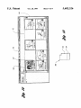
1
USO05682 326A
‘
United States Patent [191
[11]
Klingler et a].
[45] Date of Patent:
[54] DESKTOP DIGITAL VIDEO PROCESSING
SYSTEM
[75] Inventors: Joseph W. Klingler; Clifton L.
Vaughan. both of Toledo. Ohio;
Gregory M. Millar. Pleasanton. Calif.
Patent Number:
5,682,326
Oct. 28, 1997
Animation Production Environment (apE) Version 2.0
User’s Manual. copyright 1990. Ohio State University. title
page and pp. 8-9.
D. Ingalls et al. “Fabrik: a visual programming environ
ment.” in OOPSLA '88 Conf. Proc., pp. 176-190 (1988).
RE. Haeberli. “ConMan: a visual programming language for
interactive graphics.” SIGGRAPH ‘88 Conf. Proc.. Comput.
[73] Assignee: Radius Inc.. Sunnyvale. Calif.
Graph. 22(4) pp. 103-111 (1988).
MP. Stovsky et al.. “Building interprocess communication
[21] Appl. N0.: 415,854
[22] Filed:
Apr. 3, 1995
models using STlLE.” in Proc. Hawaii Int. Conf. Systems
Sciences. vol. 2. 639-647. IEEE (1988).
Primary Examiner-Alpus H. Hsu
Assistant Examiner-deem S. Rao
Attorney Agent, or Firm-Brooks & Kushman RC.
Related US. Application Data
[63]
Continuation-impart of Ser. No. 924,714, Aug. 3, 1992, Pat
No. 5,404,316.
[57]
[51]
[52]
Int. Cl.6 ................................................... .. G06K 15/00
US. Cl. ........................................................ .. 364/514 A
Field of Search ...................... .. 364/514 A; 348/563.
microprocessor. random access memory. storage memory.
[58]
348/564. 578. 581. 584. 590. 588; 358/310.
311; 395/100. 161. 114. 116-118. 153-157.
159
[56]
ABSTRACT
A digital image processing system includes a
input. display. and suitable logic to provide existing digital
video image processing operations in a graphical user inter
face which allows the user to quickly and e?iciently edit a
movie. The system includes logic for displaying the
assembled video and audio media. transitions. and special
effects in a series of independent. time-correlated tracks
which provide the system operator with a linear view of the
References Cited
movie as well as a quick understanding of the data?ow
U.S. PATENT DOCUMENTS
3,617,626
11/1971 Bluth et a1. ........................... .. 358/311
4,538,188
8/1985
4,635,136
l/l987 Ciampa et a1.
4,660,101
4,675,755
4/1987 Martin ............... ..
6/1987 Baumm'ster et a1.
4,685,003
8/1987 Westland
4,717,971
4,729,044
4,873,585
Barker . . . . . . . . .
. . . . . ..
360/143
364/948.“
358/342
.... .. 348/26
358/335
l/l988 Sawyer ...... ..
358/311
3/1988 Kiesel ........... ..
360/14.1
10/1989 Blanton et al. ....................... .. 358/335
(List continued on next page.)
OTHER PUBLICATIONS
Abode Premier product circular. printed Oct. 1991.
DiVa VideoShop product circular.
Digital Equipment Corp. Advanced Visualization System
associated with the processing of the constituents of the
movie at any point in time. In one embodiment. the system
preserves the data?ow associated with processing a video
clip by storing the information associated with that clip in a
composite data file which includes not only the digital movie
media in a conventional format. but also includes an addi
tional data segment having the appropriate indices to any
source clips and image processing effects. including the
necessary timing and parameters for reproduction of the
resultant clip. The system also preferably includes logic for
creating. maintaining and displaying a separate render track
which maintains the media corresponding to the portions of
the program that have already been rendered in proper
synchronization with those portions of the program that have
been edited since the last rendering. thereby limiting any
future rendering to those portions of the program which
require reprocessing since the last rendering of the program
of the movie.
(AVS) User’s Guide. May. 1992. cover page. and pp. 1-5.
1-6. 1-7. l-8. 1-9. 1-10. 1-11 and 1-12.
4 Claims, 9 Drawing Sheets
KEIIIIHIIIUIIDM
[E3
ammlauulani
15E
Some Wm
m
a II!!!
Ountim
@
Program lune
Duncan
5,682,326
Page 2
US. PATENT DOCUMENTS
5,012,334
4/1991 Etta ...................................... .. 360/141
5,119,474
5,175,622
6/1992 Beitel et a1. .......................... .. 395/154
12/1992 Inoue at a], __________________________ “ 358/183
4,937,685
6/1990 Barker .................................. .. 360/141
4,939,594
7/1990
4943 866
4:949:187
7/1990 Barker
8/1990 Cohen
358/335
.. ass/33s
8/1990 Kiesel
_ 360/141
5,355,173
4,949,193
Moxon ..
Barker
. 360/14.1
.
5,191,645
$306,929
3/1993 Carlwcm et a1. ..
‘"1993 Laugh“! e‘ 31- ~
10/1994 Fujita .......... ..
Soohoo
. . .. .
. 395/159
- 358/311
. 348/593
4,964,004
10/1990
__ 358/335
5,448,315
9/1995
. . . .. 348/722
4,979,050
12/1990 Westland .............................. .. 360/141
5,521,841
5/1996 Armanet a]. ..................... .. 364/514A
US. Patent
Oct. 28, 1997
5,682,326
Sheet 1 of 9
32
1 Tracks" '
'
. DIgitize‘TQ
'Eo‘mments":
-
-
3%» 2
.
,
US. Patent
0a. 28, 1997
Sheet 2 of 9
5,682,326
conedH
~
frag
.
%@Q
,.
US. Patent
0a. 23, 1997
Sheet 4 of 9
-- 1cm
.1. . . :.
NR
».Ll
mocznm
096:
_
oonv06H :.12.1:.: .
o
.5rH_..h.$§.i€ q
?g..
5,682,326
US. Patent
Sheet 5 of 9
Oct. 28, 1997
COMPOSITE
V
V
FRAME I
a???
5,682,326
US. Patent
Oct. 28, 1997
Sheet 6 0f 9
5,682,326
RENDER CHECK
/'
CLIP
INSERTED OR
CALL
REMQVED
A
T
CALL
B
202
KEY
FRAME ADDED
OR REMOVED
CALL
B
?
20a
TRANFéI’TTDN
9<
ADDED
E
210
N0
@
206
MARK m AND
\ DuT POINTS OF
AFFECTED
SEGMENT 0F
TRACK
(‘P
ADJUST
204
DOWNSTREAM
_/
IN. OUT PTS
To SYNC“
RENDER m
W/MEDIA TR.
US. Patent
0a. 28, 1997
Sheet 7 of 9
.
._
,.
E
.
. , l_‘
_.
.-k
I
1
5,682,326
US. Patent
[46
[132
r‘au‘'TRs,IvM
TFI M
130/
0a. 28, 1997
Sheet 8 of 9
5,682,326
US. Patent
Oct. 28, 1997
5,682,326
Sheet 9 of 9
H MEI
591 83%.0,9‘
DE4/
H$5.5
.2w
5,682,326
1
2
DESKTOP DIGITAL VIDEO PROCESSING
SYSTEM
RELATED APPLICATION
This application is a continuation-in-part of application
Ser. No. 924.714. US. Pat. No. 5.404.316. ?led Aug. 3.
1992.
purpose deslctop computer to quickly and easily edit movies
in a non-linear environment.
It is another object of the present invention to provide a
video digital image processing system including an interface
which allows the user to assemble and edit a movie in an
integrated multi-window environment which allows for
quick access to source media. creation. organization. and
quick recovery of movie clips. arrangement and assembly of
BACKGROUND ARI‘
selected clips. implementation and quick preview of desired
transitions and special effects. and expeditious rendering of
Editing videotape using conventional equipment and
methods can be expensive and tedious. The process is
essentially linear (i.e.. modi?cation of an earlier portion of
a movie affects. and requires reprocessing. of the later
portions of that movie). resulting in a restrictive editing
the ?nished movie.
It is another object of the present invention to provide a
environment which includes signi?cant reprocessing of
ing to render the digital media corresponding to a completed
movie.
It is another object of the present invention to provide a
data structure for storing digital movie media which can be
stored and recovered to both play back the digital movie. and
recover the necessary information required to reassemble the
unedited media.
digital image processing system requiring minimal process
15
A number of digital video image processing and editing
systems have been developed for use on desktop computer
systems. Existing desktop digital video editing systems
typically provide the capability for arranging digital movie
clips in a desired sequence. and processing selected portions
of these clips to. for example. provide transitions between
clips or special effects. in order to produce a digital movie.
These existing systems also typically include the capability
of writing the ?nished digitized movie to another media.
such as videotape. These systems may also employ various
compression techniques to reduce the amount of digital data
20
25
compressed format. signi?cant processing time is required
particularly where the entire movie is reprocessed each time
a portion of it has been edited. And. while existing digital
video systems provide the video editor with a non-linear
editing environment. the user interface of the systems is
operations necessary to achieve a different desired result.
30
magnetic disk. input means. display means. and suitable
logic to provide existing digital image processing operations
35
Also. in existing systems. once the arrangement. cutting.
and editing of a movie has been completed. the digital media
corresponding to all of the frames of the movie must be
processed. or rendered. When the rendered media is
generated. a complete digital video is created which can be
played back on the appropriate available hardware.
for quick and easy creation. organization. and assembly of
The system of the present invention includes logic for
displaying the assembled video and audio media. transitions.
and special e?’ects in a series of independent tracks. each
correlated to a third parameter. such as a horizontal time line.
The sequence of the clips. and the location and duration of
45
transitions and special effects. as well as the associated audio
tracks. can be correlated at a glance to a horizontal time line
50
display of the independent tracks allows for quick under
standing of the data?ow associated with the processing of
the constituents of the movie at any point in time.
The system also includes logic for maintaining the media
and special e?iects (“FX”) tracks as independent data
of the movie. Moreover. the vertical arrangement of the
tion is lost. or stored in another unrelated project ?le.
The words “video” or “movie” as used herein are intended
to refer to any electronic display of digital data sequences as
movie) media may include one or more “clips" each of
which are subsets of the movie. Each clip is itself a movie
entities. which are synchronized (or correlated) to a common
comprising a sequence of one or more frames of images
reference such as SMPTE codes. or other references to a
(and. optionally. sound). As used herein. a “program” is a
meaningful sequence of clips. transitions. and special
55
an additional control to the operator, including the ability to
replace media without affecting the e?fect itself. the ability to
control the pacing (overall time) of an effect independent of
It should be noted that the words “desktop” or “personal”
computer as used herein are intended to refer to any of the
currently available general purpose single-user computers
clip length or content. and the ability to save an e?'ect and
which may operate independently or network and may
incorporate suitable software to perform other. non-video
reapply it to another time segment.
The system of the present invention may also include
processing functions. such as word processing. graphics.
suitable logic for creating data?ow graphs recording the
database. and spreadsheet functions.
a digital image processing system which utilizes a general
common time line or frame number. It will be appreciated
that the separation of the media clips from effects provides
elfects. assembled by an editor into a movie.
DISCLOSURE OF INVENTION
It is. therefore. an object of the present invention to create
in a graphical user interface which allows the user to edit a
movie in the less restrictive non-linear digital image envi
ronment including multiple integrated windows which allow
clips into a movie.
However. all of the information required to assemble the
movie. such as the identi?cation and location of the portions
images (and. optionally. sound). As used herein. video (or
In carrying out the above and other objects. the digital
image processing system of the present invention includes a
processor. random access memory. storage memory. such as
often cumbersome.
of the source clips utilized. the transitions and special
elfects. and the associated processing and timing informa
a digital video processing system which automatically
records the processing operations selected to perform a
particular video edit. so that variations in the editing process
can be accomplished by recalling the original editing opera
tions and reprocessing only those portions of the editing
which defines a particular movie. However. even in a
to implement transitions and special etfects in the digital
regime. Thus. the processing. and reprocessing. of the digital
video image clips during editing can be time-consuming.
stored media from the source media from which it was
created.
It is yet another object of the present invention to provide
65
image processing operations. and associated parameters and
inputs selected using the interface. thereby allowing for easy
modi?cation of a previously designed set of processing
operations and reprocessing of one or more selected video
5.682.326
3
4
movie clips through recollection. alteration. and reprocess
ing of the stored data?ow graphs relating to the selected
video track. with any FX tracks associated with that media
track. In one embodiment of the invention. the system
clips. In one embodiment. the present invention effectively
correlates associated media and FX tracks with a common
preserves the data?ow associated with processing a selected
clip by storing the information associated with that clip in a
composite data ?le which includes not only the digital movie
5
media in a conventional format. but also includes an addi
tional data segment having the appropriate indices to any
source clips and image processing effects. including the
timing and parameters which produced the resultant clip. as
well as suitable synchronization information for recreating
the resultant clip.
The video image processing system of the present system
10
Conversely. a clip can be removed from the video track. and
also includes an interface capable of displaying one or more
another inserted. without changing the eifect applied during
that time period.
The system also preferably includes logic for creating.
20
display the selected clips. transitions. and special effects as
one or more horizontal tracks. independently identifying the
video and audio media. as well as any image processing
effects associated with the media. in a time line view to
provide more precise display of those clips for frame
associated e?‘ects with run time (in the Sequencer Window).
it also organizes the data associated with these entities in
independent. but time-correlated ?les. Thus. a particular
effect may be initiated during a selected time period (i.e..
inserted in the appropriate FX track at selected SMPTE in
and out points) independently of the a?’ected video media.
integrated movie-editing windows. One window displays
some or all of selected clips of a movie-in-process. playing
in real time along side a display of the source clips. Another
window displays reference clips. either in a list or formatted
as a two-dimensional array of clips with graphical identi?ers
which may be arranged in the array in a desired sequence for
assembly into a movie. A third window is formatted to
time-line in SMPTE time code units. It will thus be appre
ciated that not only does the system of the present invention
provide a graphical correlation of each media track and its
maintaining and displaying a separate render track which
maintains the media corresponding to the portion(s) of the
program that have already been rendered in proper synchro
nization with those portions of the program that have been
edited since the last rendering. By recording any edits to the
program and determining the effect of those edits on any
downstream (i.e.. later-in-tirne) portions of the program. the
render track automatically keeps track of those portions of
25
the rendered program which must be re-rendered at any
accurate editing. These windows. known as the Monitors.
point in time. When the program is rendered. the system
Project. and Sequencer Windows. respectively. together pro
vide a complete composition and editing environment which
processes the source media referenced in all of the reference
clips (i.e.. all of the clips in the Sequencer Window tracks)
utilizing the selected instructions for adding transitions and
allow the user to organize and process movie clips into a
?lters. Once rendered. a single media unit—-a video
program-is created for review or. if desired. for printing to
desired end product.
The Monitors Window is. in substantial part. two frame
sized sub-windows. One of the frame-sized sub-windows is
a source monitor which displays the digitized source clips.
The adjacent sub-window allows the user to view one or
more selected clips that have been de?ned and/or processed
using the editing system of the present invention. AMonitors
35
re-rendering only those clips which have been edited. or
which are affected by clips which have been edited. since the
Window includes standard controls to start and stop the
movies in either of the sub-windows. as well as control the
sound volume. and de?ne in and out points to create
last rendering.
The present invention also preferably accomplishes many
of the image processing techniques on multiple key frames
of selected clips by progressively altering the frames of the
reference clips.
In one embodiment of the invention. a second. external
designated clip on the basis of modi?ed parameters inter
video monitor is utilized. preferably to display the Monitors
Window. so that the source clips and selected reference clips
can be viewed in the Monitors Window while the operator
is simultaneously viewing and working in other system
polated (or extrapolated) from speci?ed parameters for the
key frames.
45
tor.
ment.
The Project Window preferably provides two alternate
project. In the Text View. the Project Window displays an
alpha-numeric list of selected clips. In the Picture View. the
50
Project Window displays some or all of the selected clips on
an adjustable mxn array wherein each of the clips is iden
The present invention also preferably includes logic for
correlating each media track. such as for example the ?rst
These and other objects. features. and advantages of the
present invention are readily apparent from the following
detailed description of the best mode for carrying out the
invention. taken in connection with the accompanying draw
rugs.
ti?ed by a selected image frame and. optionally a title bar.
The Sequence- Window provides a graphical time-line
view of the selected video and audio media along with the
associated processing e?'ects applied to the media to yield
the resultant movie. The Sequencer Window is particularly
useful for assembling selected clips into a movie. since the
linear view of the video and audio material and the display
of the synchronization of the effects applied to that media.
facilitate quick. detailed editing decisions. The output of any
editing operations are synchronized with. and may be
viewed on the Monitors Window.
The present invention also provides a toolbox of digital
image processing ?lters for movies which can be de?ned.
combined. and previewed in a visual programming environ
editing windows displayed on the primary computer moni
views of the reference clips collected for a particular movie
videotape. The processing time associated with the applica
tion of special effects ?lters and transitions is signi?cant.
The render track. however. shortens this processing time.
and thus speeds up the rendering of the movie. by
BRIEF DESCRIPTION OF DRAWINGS
FIG. 1 is a schematic view of the system of the present
invention;
FIG. 2 illustrates a Digitizer Window;
FIG. 3 illustrates a Monitors Window;
FIG. 4 illustrates a Project Window in Text View;
FIG. 5 illustrates a Sequencer Window;
FIG. 6 illustrates a data?ow chart which may be derived
from seeing the media and FX tracks in the Sequencer
65
Window;
FIG. 7 illustrates a Sequencer Window with an expanded
view of a transition between two clips;
5,682,326
5
6
FIG. 8 is the data?ow diagram of a representative tran
sition and a representative effect performed on selected
user interface including a conventional menu bar from
which any of a number of windows may be opened and
utilized in editing a digital movie. As with other conven
frames of two adjoining clips;
FIG. 9 is a ?owchart illustrating the rendering logic
tional Graphical User Interfaces (GUI’s). the commands
available under each of the menus may be displayed by
keystroke command. or by positioning the arrow over the
desired menu name and clicking to “pull down” the avail
employed in one embodiment of the invention;
FIG. 10 illustrates the Monitors Window in FX View;
FIG. 11 illustrates the Monitors Window in Trim View;
FIG. 12 illustrates the Project Window in Picture View;
and
FIG. 13 is a schematic representation of a composite clip
able commands. Again. as with conventional pull down
menu interfaces. the commands are invoked by holding the
mouse button down and positioning the arrow 66 down the
menu until the desired command is highlighted. then releas
ing the mouse button. A desired command may also be
utilized by the system of the present invention.
BEST MODE FOR CARRYING OUT THE
H‘IVENI'ION
Referring now to FIG. 1. the video image processing
system of the present invention generally indicated as 20
includes a conventional desktop computer 22 including at
invoked by striking the key combinations listed in the
pull-down menu opposite the command. Consistent with
conventional GUI's. the user may move from an active
window to another window by positioning the cursor to the
other window and “clicking” on it. Alternatively. the user
may position the cursor on an icon associated with the
desired Window or action and “click” on the icon. Again. as
with conventional GUI’s. the user may double click on a ?le
to load the data in the ?le or. if the ?le is a program. run the
program. For example. the user may position the cursor over
least one processor 24. random access memory 26. storage
memory 28. and suitable logic 30 to implement the image
processing operations in the visual programming environ
ment as hereinafter described. The system also includes at
least one display 32. and one or more input devices such as
a conventional keyboard 34 and/or mouse 36. The system
also preferably includes a second display 38. such as an
the clip displayed in the Monitors Window and double click
to play that clip.
It should be noted that. in the embodiment of the inven
tion which employs a second video monitor 38. each of the
monitors 32 and 38 in the system are con?gured for a
In one embodiment. the system utilizes an Apple Macin
seamless mouse movement. For example. if the external
tosh series. having a Motorola 680X0 (68020. 68030. and
monitor 38 is sitting to the left of the computer monitor 32
68040) series microprocessor. at least 32 megabytes of
RAM. at least 200 megabytes of disk memory. a conven 30 when in use. the system is con?gured so that. to move the
mouse pointer from a point in the display of the computer
tional keyboard with numeric keypad. and conventional
monitor 32 to a position on the display of the external
mouse or roller ball. This embodiment of the system also
monitor 38. the operator may drag the mouse off the left side
employs Apple System 7.1 (or later) operating system.
external television standard (e.g.. NTSC) monitor.
QuickTime 2.0. Macintosh Drag and Drop Manager. Apple
Sound Manager 3.0 (or later). and QuickDraw GX 1.0 (or
25
of the computer monitor screen to see it appear on the right
35
later) video software.
Other commercially available general purpose desktop
computer hardware with similar color graphics capabilities
edge of the external monitor. Again. this seamless integra
tion of the mouse pointer with multiple monitors is achieved
through the use of conventional monitor control software.
FIG. 2 illustrates a Digitizer Window which is used in one
and comparable digital video support software may also be
embodiment of the present invention. The Digitizer Window
utilized for this purpose.
may be utilized to control an external video machine to
‘ capture and digitize the source video. as Well as select in and
Logic suitable for providing the image operations. ?le
utilities. and the visual programming interface hereinafter
described are preferably programmed in a Unix language
such as “C” or “CH.” Again. however. other similar general
purpose programming languages may be utilized to imple
ment the logic and interface described herein.
It will be appreciated that the system of the present
invention can be implemented with features found in other
image processing software systems. such as those illustrated
and described in U.S. Pat. No. 5.404.316. which is hereby
45
50
out points to de?ne the source clips. The clips are preferably
de?ned by a clip identi?er. the in and out points for the clip
(preferably in SMP'I'E time codes). and any comments
relating to that clip. Once de?ned. the source clips. either
individually. or in groups. are then digitized
It will be appreciated that. while the system 20 may
provide a Digitizer Window or other external device control
window as described above. other conventional techniques
and equipment may be utilized to digitize and mark the
incorporated by reference for that purpose. In particular. the
Sequencer Window with its independent. time-correlated
source clips. which may then be edited as described herein
on the system 20.
media tracks. FX tracks. and rendering track. as well as the
composite clip data ?le structure can be implemented in a
variety of video image processing environments. such as
that disclosed in U.S. Pat. No. 5.404.316. without departing
Referring to FIG. 3. after digitizing. the clips can be
reviewed in the Monitors Window 46. In particular. the
digitized source clips are displayed in the source monitor
sub-window 48 of the Monitors Window 46. The Monitors
Window 46 also includes graphical button controls 50
55
from the spirit of the present invention.
It will also be appreciated that. in particular. the data?ow
corresponding to conventional video players. Reference
clips can be created from source clips by viewing selected
concepts. as described in FIGS. 2. 16 and 17. and the
attendant speci?cation of U.S. Pat. No. 5.404.316. may be
portions of the source clips in the source monitor sub
window 48. selecting in and out points. and naming each of
incorporated into the system of the present invention. to
provide an improved digital video movie editor. Again. the
disclosure of U.S. Pat. No. 5.404.316 is also incorporated by
the reference clips. A slider bar or other suitable controls
allow the user to de?ne beginning and end points for
reference clips. Thus. playing the source clips in the Source
reference herein to the extent that it pertains to these
dataflow concepts.
Referring now to FIGS. l-S. the display 32 (or.
optionally. the displays 32 and 38) provide(s) a graphical
65
Monitors sub-window 48 allows the user to view exactly
what has been digitized to disk (the source clips) as well as
de?ne reference clips to be utilized in assembling a program.
5,682,326
7
8
As with the other Windows comprising the interface of the
As the program is graphically assembled in the Sequencer
present invention. suitable conventional graphical buttons.
Window 76. some portion or all of the program may be
viewed in the program monitor sub-window 54 of the
Monitors Window 46. The portion of the program to be
viewed in the program monitor sub-window 54 may be
selected by moving the time line cursor 106 over the desired
slider bars. or other graphical switches or controls may be
included in the windows to eifect “point and click” activa
tion of the functions within the windows. Alternatively. or in
addition. pull-down menus. and/or selected keyboard com
mands may be implemented to provide the user with the
starting frame of the clip. Alternatively. or additionally. the
ability to input information and/or control the various func
tions performed by the system.
Once the reference clips have been de?ned and collected.
a program can be created using the editing system 20 of the
present invention. A program is a meaningful sequence of
reference clips created from the source clips. A reference
clip does not contain the actual digitized media. Instead it
contains references back to the media in the source clips.
10
(not shown) or other suitable keystroke command. vWhen a
clip is selected from the pop-up menu in the program
monitor sub-window 54, the time line cursor 106 in the
Sequencer Window 70 moves to the beginning of that clip.
If the clip is not currently visible in the Sequencer Window
70. the view in the window changes to display the clip at the
including in and out points (clip beginning frame and clip
ending frame). for that reference clip. It should be noted that
the reference clips de?ned and created for a particular
program do not necessarily have the same in and out points
as the source clips which contain the media referenced in the
reference clips.
Once created. the reference clips for a particular movie
project may be organized in the Project Window 60. As
shown in FIG. 4. the Project Window may be displayed in
Text View. resulting in the display of all of the clips in a
particular project group or bin. In Text View. the Project
program monitor sub-window 54 may provide access to
select any of the clips in the program assembled in the
Sequencer Vlfmdow 70 via a conventional pop-up menu
which can be activated by pressing a program menu button
center of the window.
Referring again to FIG. 5. the system preferably provides
20
a plurality of pre-de?ned special elfects which may be
applied to the selected clips as desired. In one embodiment.
these effects are applied using conventional ?lters. including
color adjust. fade. mirror. picture-in-picture. tint. and titling.
The desired ?lter is selected from a pop-up menu which is
25
accessed using conventional menu activation commands.
and the ?lter is selected and dragged into an FX track 86 in
Window 60 lists certain selected information about all of the
clips in a particular bin in the clip sub-window 62. This
the Sequencer Window. The parameters for controlling the
information typically includes the clip name. clip duration.
a ?lter control window which. again. is activated by using
conventional menu activation techniques.
The system 20 preferably allows the user to specify ?lter
in and out points (typically in SMPI'E time codes), the
number and type of tracks comprising the clip. comments.
status and tape ID. The status of a clip typically indicates
operation of the filters may be set for selected key frames via
30
parameters for two or more key frames. The system then
whether the clip is a reference to source media that is still on
videotape. or to media that has been digitized and stored on
disk. The clips are grouped in bins which are separately
displayed in the bin sub-window 64 of the Project Window.
calculates the appropriate progressive values to allow the
35
Referring now to FIG. 5. the system 20 of the present
invention includes a Sequencer Window 70 which provides
a graphical representation of a time line 72 and multiple
associated tracks 74-83. into which reference clips contain
ing video and/or audio media. and processing functions.
such as clip transitions 84 or special e?’ects ?lters 86. can be
arranged and correlated in time. A program. that is. a
collection of reference clips. may men be assembled in the
mathematical models or other data sources as modulators. to
Sequencer Window 70 by opening the desired number of
video. FX. and/or audio tracks. and arranging the media
and/or elfects in the desired sequence. As illustrated by the
example in FIG. 3. a program can. for example. be created
to include some portion or all of the “ledge shot” video clip
90 followed by the “be on glacier” clip 92 and thereafter
allow the user the capability of dynamically changing the
effect of a ?lter without specifying individual ?lter param
eters for each frame of the media affected by the ?lter. For
example. a known “spline" (or smooth curve) may be
utilized as a mathematical template for interpolation
50
followed by the “twist shot" clip 94. These clips can be
dragged into the Sequencer Window 70. either from the
Project Window 60 or from the Source Monitor sub-window
48 of the Monitors Window 46 by using conventional drag
and drop techniques. The starting point and ending point of
55
In the example illustrated in FIGS. 5 and 6. a color adjust
The amount of detail seen in the time line window may
e?ect has been selected and placed on an FX track 86. The
also be varied by activating the zoom in and zoom out
buttons 96 and 98 on the window. A Sky View sub-window
selected clips which are positioned in video track V1 during
the time sequence covered by the color adjust ?lter will be
processed through that ?lter. Thus. a special effect may be
100 may also be provided. The Sky View sub-sub-window
Sequencer Window 70.
abruptly changes the elfect at the next key frame (and
thereafter if appropriate) according to the parameter set for
that key frame. Other templates may be utilized for inter
polation including data from the media (both video and
audio) itself.
sequencer time line.
portion of the program that is currently visible in the
between key frames. Also. in place of intm’polation. the
system may provide a “hold" feature which identically
modi?es all of the frames subsequent to a key frame in an
identical manner to that de?ned for that key frame. then
the reference clips can be changed. and/or the clips can be
moved relative to other clips simply by clicking on and
dragging the graphical representation of the clip in the
illustrates the entire program. preferably as color-coded
tracks. and includes an indicator 102 which identi?es the
?lter to gradually change the value set in one key frame to
the values set in the next adjacent key frame so that the
?lter’s affect on all of the frames between two adjacent key
frames may be interpolated. It will be appreciated that by
using multiple key frames. the system allows the user to
change the rate of change effected by the ?lter over the
length of the ?lter. It will also be appreciated that. While in
one embodiment of the present invention the interpolation
between key frames is linear. other non-linear. and/or dis
continuous rates of interpolation can be implemented. using
associated with a particular sequence in a video track
65
through time correlation of the e?’ect with the clips in that
track. By utilizing a separate FX track. the e?‘ect is associ
ated with a time sequence in the program rather than a
5.682.326
10
by opening a transition dialog box using conventional menu
particular clip or clips. Thus. for example. one or more of the
activation techniques. In one embodiment of the present
invention. the video track containing a transition may be
clips may be removed and/or replaced with another clip by
simply clicking and dragging the appropriate clip into posi
expanded to graphically illustrate how the transition is
positioned in relation to the clips it is used with. For
example. as shown in FIG. 6. by activating toggle button
108. video trackVl is expanded vertically so that the “ledge
shot” clip is shown positioned in a track above the dissolve
tion in the video track V1. and the preselected ?lter will act
on whatever clip has been placed in the corresponding time
sequence occupied by the ?lter in the FX track FXl.
Referring to FIG. 6. the graphical display of the
Sequencer Window 70 indicates the data?ow of the media
for each point in time (i.e.. for each frame) of the program.
By correlating the media and FX tracks with a selected point
in time (or a selected frame). the user can glance along the
transition. which in turn is positioned above the “be on
glacier" clip. Each of the clips. as well as the transition.
remain correlated with the time line 72 in the Sequencer
Window 70. This expanded view may illustrate. for
example. that one of the clips does not extend through the
entire period of the transition. Thus. “ledge shot” ends
before completion of the dissolve transition. This is illus
time line cursor 106 in the video and FX tracks to ascertain
what media is input through what eifects ?lter or ?lters at
each frame of the program. It should be noted that the system
allows the user to add as many FX tracks as desired for any
video track. so that each ?lter. as well as each media clip is
trated by a shaded section 110. indicating an absence of
media in the “ledge shot" clip for a portion of the dissolve
transition. It will be appreciated that. since the system
maintains the media tracks and transitions as independent
independently displayed in vertically stacked tracks which
are each synchronized with a horizontal time line.
It should also be noted that the system may allow for the
creation. and editing. of multiple video tracks as well as
multiple audio tracks. As shown in FIG. 6. a second video
entities. a desirable eifect or transition. once created can be
easily copied and moved to another location in the program.
Thus. for example. the dissolve transition could be copied
and moved to the junction between the “be on glacier” clip
track. V2. as well as other multiple tracks are combined
during rendering by utilizing conventional compositing (or
layering) techniques. In one embodiment. for example. the
system performs an alpha composite of each of the synchro
25
and the “twist sho ” clip, without altering or affecting any of
the media.
The system preferably provides several ways to view a
nized multiple video tracks of a program on a frame-by
transition before rendering the entire program By clicking
?'ame basis during rendering. Other composite techniques
on the transition 84 on the time line in the Sequencer
could. of course. be utilized without departing from the spirit
of the present invention.
It will be appreciated that the independent FX tracks is
advantageous to the e?icient operation of the system as well
as being a useful graphical interface for the operator. By
Window 70 and dragging the time line cursor 112 through
the transition. a low quality. high-speed version of the
transition is displayed in the FX monitor sub-window 120
(shown in FIG. 9) of the Monitors Window 46. By clicking
selected effects ?lters to a common parameter such as 35
on the transition 84 in the Sequencer Window 70 and
activating another pre-selected command. an animation of
the transition can be viewed Finally. by moving the time
elapsed time or frame number. a system can process any
line 106 to a selected frame in the transition 84 and acti
time-synchronized. or otherwise correlated media and
vating another preselected command. a snap shot of one
frame of the program. at that point in the transition. is
correlating the digitized media in with the one or more
?lters. regardless of whether the clips providing the media
input at any selected point in time have been changed. Thus.
in contrast to previous image processing regimes which
associate a particular processing operation with particular
displayed at ?nal image quality. It will be appreciated that
these various preview options allow the user to select an
option that balances the con?icting considerations of mini
mizing processing time and maximizing image quality dur
ing the editing stage.
selected media. the correlation of effects and media with a
common parameter. such as time. allows for substitution of
media or effects. with minimal restructuring of the process
Referring to FIG. 8. it will be appreciated by those skilled
in the art of digital video image processing that the graphical
display of the Sequencer Window 70 suggests a frame-by
mg.
Referring again to FIG. 5. in addition to creating and
assembling reference clips into a program. the system of the
frame data?ow for the program. For example. a transition
present invention allows the user to implement a variety of
transitions between the clips. The most common transition is
a cut. which is an instantaneous switch from one clip to the 50
(particularly when displayed in the expanded view shown in
FIG. 7) graphically illustrates that at any point in time (i.e..
at any single frame) there are video inputs (i.e.. image
next. Acut transition occurs whenever two clips are arranged
frames) from two clips 90 and 92 which are processed as
adjacently in the Sequencer Window. The system also pref
inputs through a transition ?lter 84 to yield a single output
frame 95. And. in the example illustrated in FIGS. 5 and 6.
at any selected point in time during the transition 84. the
output frame 95 is then processed by a special effects ?lter
tnably includes several conventional transitions such as a
cross-fade audio transition. a dissolve transition. an iris
transition. a radial wipe transition. and a wipe transition. To
employ any of these transitions. the desired transition is
selected from a sub-window which is opened by clicking on
the appropriate command from a conventional menu bar.
55
86 to yield a ?nal frame in video track V1 at the selected
point in time. The Sequencer Window 70 thus illustrates the
concept of program linearity by correlating the individual
pop-up window to the junction point between the two clips
media and FX tracks with a time line. while suggesting the
data?ow of any image processing performed on the media at
for which the transition is desired. In one embodiment. the
any selected point in time merely by glancing vertically
system displays the transition as a two-toned gold strip
down the time cursor line 106 in the window.
overlaying the clip junction.
Referring to FIGS. 5 and 9. the system 20 may employ.
and display. separate render tracks 82. 83 corresponding to
The desired transition is then selected and dragged from the
In FIG. 5. a dissolve transition 84 has been placed
between the “ledge shot” clip 90 and the adjacent “be on
glacier” clip 92. The duration of the transition. as well as any
other parameters associated with the transition. may be set
65
the media tracks in a program. When displayed. the render
track 82 for a corresponding video track 74 graphically
indicates. as. for example. by shading. those portions of the
5,682,326
11
12
program which will require re-rendering. and those portions
of the program which do not require re-rendering. since the
last rendering. In the example shown in FIG. 5. that portion
special effects created with ?lters in several ways. First. a
high speed (i.e.. relatively rapidly processed) version of a
?lter operation may be viewed at relatively lower video
quality by clicking the ?lter on the time line in the Sequencer
Window 70 and dragging the time line cursor through the
85 of the render Rack 82 to the left of the time line cursor
106 is shown by relatively lighter shading to have already
been rendered. while the portion 87 of the render track 82 to
the right of the time line cursor 106 is shown. by relatively
darker shading. to require rendering. By keeping track of
what portions of the program media require rendering since
the last edit. the system 20 limits time consuming repro
cessing.
10
FIG. 9 illustrates a simple algorithm for determining what
portions of a program require rendering. In a routine that is
called periodically. such as an interrupt routine. the system
20 checks to determine whether any editing action has been
taken by the operator. For example. the system checks. at
?lter. The results will be displayed in the FX monitor
sub-window 120 of the Monitors Window 46. Similarly. the
fully processed effect of a ?lter at ?nal image quality may be
viewed by clicking on the filter in the time line in the
Sequencer Window 70 and pressing a preselected command
(such as the Shift key) while dragging the time line cursor
through the ?lter. Again. the results are displayed in the FX
monitor sub-window 120. Another method of previewing
the eifect of a particular ?lter. reviewing an animation of the
?lter. can be accomplished by selecting the ?lter on the time
line in the Sequencer Window 70 and clicking the animate
button (or selecting some other prede?ned keystroke).
202 to determine whether a clip has been inserted or
Reviewing an animation of a ?lter’s operation is particularly
removed from a track. If. for example. a video clip has been
useful because it provides the operator with a view of how
inserted or removed. the system would then. at 204. adjust
the downstream in and out points on the media on the 20 the ?lter works in “real time” with minimal processing. since
the actual video media is not processed at each frame. This
atfected track to correlate the downstream in and out points
or deletion of the clip. For example. if the “mega jump” clip
(listed in the Project Window 60 in FIG. 4) is inserted in
preview thus provides the operator with an opportunity to
adjust the pacing of the ?lter before any rendering of the
program.
Finally. a snap shot of any single selected frame of the
video track 1 before the “twist shot” clip. the in and out
points of the “twist shot” clip and any downstream clips
program. including any special eifects ?lters. may be viewed
at ?nal quality by moving the time line in the Sequencer
would be adjusted on both the video track 74 and the render
track 82 by 19:19. The system 20 would then mark the in
Window 70 to the frame you want to see and clicking the
on the render track with the downstream media on the media
track that has been repositioned as a result of the insertion
point of the “mega jump” clip (in this example. at the time
snap shot button (or pressing some other preselected
30
command).
line cursor 106 in the Sequencer Window 70 in FIG. 5) and
the out point (19:19 frames later) of the render track to
indicate that this segment must be re-rendered.
The system 20 similarly checks. at 208. to see if a key
Referring to FIG. 11. the Monitors Window 46 may also
provide a Trim View which includes two Trim monitor
clip. including frames before and after the added or removed
key frame. will be marked. at 206. on the render track. to
again indicate that that portion of the media must be
re-rendered. It should be noted that the location and numbm'
of frames a?ected by a change in a key frame will be
simultaneously lengthening the other in order to maintain
the constant length of the combined adjacent clips. The Trim
View of the Monitors Window 46 may be activated by
sub-windows 130 and 132 for displaying selected portions
of adjacent clips during roll editing. Roll editing lets the
frame has been added or removed. If so. some portion of the 35 operator edit adjacent clips in a track—shortening one while
pressing a ‘Trim” button on the Monitors Window itself or
by selecting the appropriate command from a pull-down
menu. or by implementing a prede?ned keystroke on the
dependent upon the type of interpolation (i.e.. linear.
curvilinear. or discontinuous) employed.
keyboard. When activated. the selected adjacent clips are
displayed in each of the Trim monitor sub-windows 130 and
The system 20 also checks. at 210. to determine whether
any effects ?lters or transitions have been added or removed.
If so. the system 20 marks the corresponding in and out
points on the render track to indicate that re-rendering is
132. with the selected end frame of the ?rst of the two
45
right sub-window 132. By activating the appropriate buttons
required.
It will be appreciated that the system may allow for. and
must therefore monitor. other operations which might
modify the media on a particular track. Any such operations
should be analyzed. the a?ected segments identi?ed. and the
appropriate in and out points marked for re-rendering on the
in the Monitors Window 46. the length of the ?rst clip can
be shortened and the second clip extended. or vice versa.
50
render track.
In one embodiment. the system 20 allows the opm'ator to 55
manually mark portions of the render track 82 for
re-rendering. Thus. for example. if a portion of segment 85
of render track 82 were so marked. the portions marked for
re-rendering would then be displayed in the relatively darker
shading (as in segment 87). indicating that the correspond
ing portions of the associated media tracks would be
re-rendered on the next instruction to the system to render
the program.
Referring to FIG. 10. the Monitors Window 46 may also
present an FX VICW in which an FX monitor sub-window
120 is displayed adjacent the source monitor sub-window
48. As with previewing transitions. the operator can preview
adjacent clips displayed in the left sub-window 130. and the
selected ?rst frame of the adjacent clips displayed in the
Then by clicking the play button. or by activating a similar
preselected command at the keyboard or on the menu bar.
the adjacent clips can be played to view the roll edited
transition.
Referring to FIG. 12. the system 20 of the present
invention may also provide a Picture View of the Project
Window 60 wherein the clip sub-window 62 displays a
selected portion. or all of the clips located in a selected bin
in an adjustable array of frame windows in which an image
of a selected frame. such as the ?rst frame. of each of the
clips in the bin is displayed. The name of the clip may also
be displayed on a title bar 142 associated with each clip
window 140. The size of the clip sub-window 62 can be
varied. preferably through the use of conventional slider bars
144 to size the clip sub-window 62 to display the desired
number of clip windows 140 in a desired end-by-end array.
The Picture View of the Project Window 60 may be utilized
to order the clips in a desired sequence by clicking on and
5,682,326
14
13
dragging the clips to empty blocks in the Picture View 62.
zontally extending media track in which graphical
in order to achieve a preliminary sequence of display of the
clips for a program.
Referring to FIG. 13. the system 20 of the present
invention may include a composite clip data ?le structure for
any rendered movies. The composite clip data ?le 150
includes a media segment 152 which contains the digital
data corresponding to the rendered media in a conventional
format. In one embodiment. for example. the media segment
indicia of media clips can be inserted and correlated to
an independent time line. and at least one special effects
track in which graphical indicia of a special effect can
be inserted and correlated with the time line.
2. A system for processing digital movies including a
general purpose computer having.
a processor.
random access memory operably connected to the
references to each of the source clips. references to any
processor.
a display operably connected to the processor.
an input operably connected to the processor. and
logic for correlating at least one media track containing at
special effects and/or transitions. including established
parameters and key frames. and the requisite timing infor
least one digital movie clip. and at least one FX track
containing at least one special effect. with a common
mation required to reassemble the media contained in the
media segment 152 of the ?le. It will be appreciated that the
reference. thereby providing synchronization of the
152 of the composite clip data ?le could be in Apple
QuickTime® format. The composite clip data ?le 150 also
10
includes a composition data segment 154 which includes
media track with the FX track to facilitate processing of
the digital movie to obtain the special effect with the
existence of this composition information. properly stored
directly with the media in a composite ?le structure. allows
any systems that are capable of playing back the media to
open the ?le and play the media. typically as a digital movie.
For example. if the media portion of the ?le is in a Quick
Time® format. anyone with a copy of the composite clip
data ?le can play the digital movie contained in the media
?le portion 152 of the data ?le if they have a QuickTime®
system. In addition. if the composite clip data ?le 150 is read
by a system. such as the present invention. capable of
appropriate timing and parameters.
20
3. In a system for processing digital movies including a
computer having a processor. random access memory. stor
25
age memory. and logic for performing selected image pro
cessing operations on the digital movie. improved logic for
rendering the movie. the improved logic including:
(1) logic for identifying and marking digital information
corresponding to those portions of the movie that have
not been modi?ed since the last time the movie was
accessing and interpreting the composition data segment 154
rendered. (2) logic for identifying and marking the
of the ?le. the system has access to the media required to
play back the movie. as well as to all of the information that 30
been modi?ed since the last time the movie was
created the movie. This composite information thus allows
the clip to be quickly edited and recreated by an appropriate
rendered. and (3) logic for identifying and marking the
digital data for those portions of the movie that have not
been modi?ed since the last rendering but are a?ected
by portions of the movie that have been modi?ed since
system where the source material can be re-digitized or
accessed ?om storage.
While the best mode for carrying out the invention has
digital data for those portions of the movie that have
35
the last rendering. and logic for rendering only the
been described in detail. those familiar with the art to which
digital data marked in sections (2) and (3) in response
this invention relates will recognize various alternative
designs and embodiments for practicing the invention as
to an instruction to render the movie.
disclosed by the following claims.
4. In a system for processing digital movies including a
computer having a processor. random access memory. stor
What is claimed is:
age memory. and logic for performing image processing
1. A digital movie processing system including a general
operations on digital data corresponding to at least one
purpose computer having:
a processor;
movie clip. an improved composite clip data ?le comprising
an image media segment and a composition data segment.
the image media segment including digital data correspond
random access memory suitably connected to the proces 45
ing to the movie clip in a format suitable for playing the
sor;
storage memory operably connected to the processor;
an input connected to the processor; and
a display operably connected to the processor. the display
including a plurality of windows. each of the windows
having a different fonnat. and wherein one of the
windows provides a graphical time-line view of one or
more clips of the movie. including at least one hori
movie. and the composition data segment including data
corresponding to the identity and location of the source
media and image processing operations performed on the
source media. including processing and timing parameters.
suitable for reproducing the movie clip contained in the
media segment of the data file from the source clips.
*
*
*
*
*